Project 1
Routing for side door panel - Project 1
Aim:
Route the wire for the side door of a care with the necessary connector along with the guiding challenge data given TASK
- Routing assembly creation
- Flattening
- Drawing creation
Routing Assembly Creation
Catalog Creation: Download all required connectors and support parts, and create a catalog for the connectors.
Electrically Defined Parts: Define connectors and support parts electrically by creating points, planes, and axes.
Assembly: Assemble the electrically defined parts and connectors in the designated locations for the wiring harness.
Wiring and Support: Connect connectors with the wiring harness through support parts, ensuring appropriate bundle radius and slack percentage.
Protection: Cover the wires with suitable protective covers, maintaining proper distance at the start and end extremities
Different Connectors to be Used:
- Interconnection Connector: Used for connecting various wiring harness segments within the vehicle.
- Connector - Door Control Switches: Interfaces with the door control switches for operational control.
- Speaker System Connectors: Connects the wiring harness to the vehicle’s speaker system.
- Window Winding Motor Connector: Connects the wiring harness to the motor responsible for window winding.
- Door Lock Sensor Connector: Interfaces with sensors used for door locking mechanisms.
- Guiding Channel: Provides a pathway for the wiring harness and connectors, ensuring organized and secure routing.
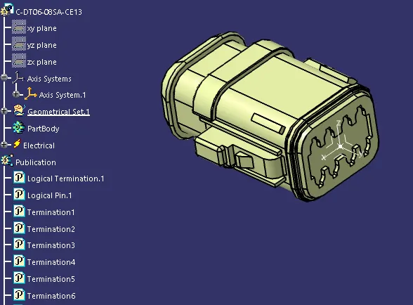
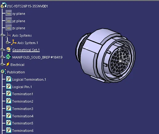
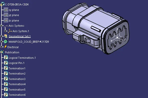
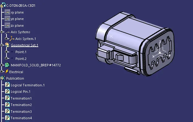
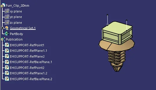
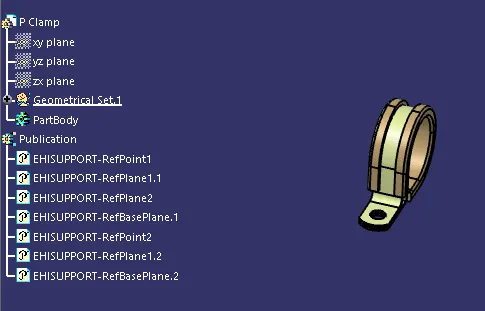
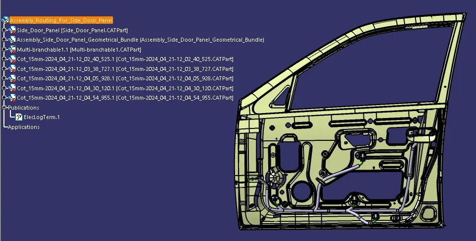
Assembly Routing For Side Door Panel
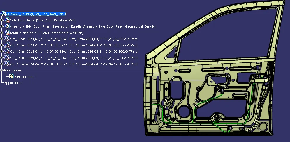
Assembly Routing For Side Door Panel with Protective Cover
 Flattening
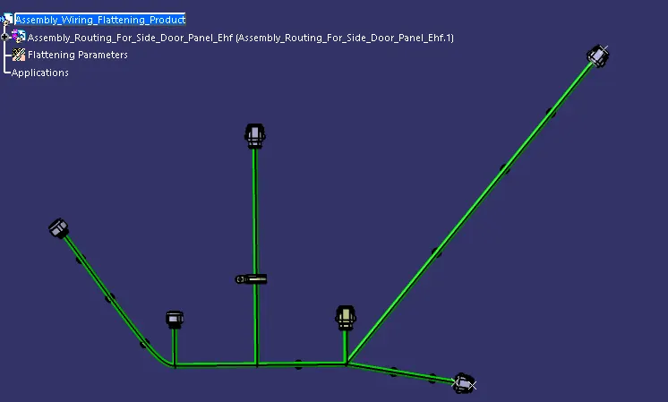
Flattening a Wiring Harness
Flattening a wiring harness in CATIA V5 involves converting the 3D harness representation into a 2D flat pattern for manufacturing and documentation purposes.
Setup: Open a new product file titled [Assembly Wiring Flattening Product]. Switch to Electrical Harness Flattening and adjust settings in the Flattening parameters for General & Drawing at [Harness Flattening Parameters].
Extraction: Tile vertically the (Assembly Routing for Side Door Panel) and use the Extract command to retrieve the necessary components.
Flattening: Use the Flatten command, select the active plane as the Connector Top Plane, and choose all branches. Click OK to create the flattened assembly.
Drawing Creation
Creating drawings in CATIA V5 involves generating 2D views from 3D models for documentation and manufacturing.
Setup: Open a new Drawing file and rename it as [Drawing 1]. Tile the window vertically with Drawing 1 and the Assembly Wiring Flattening Product.
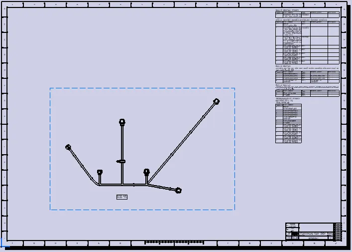
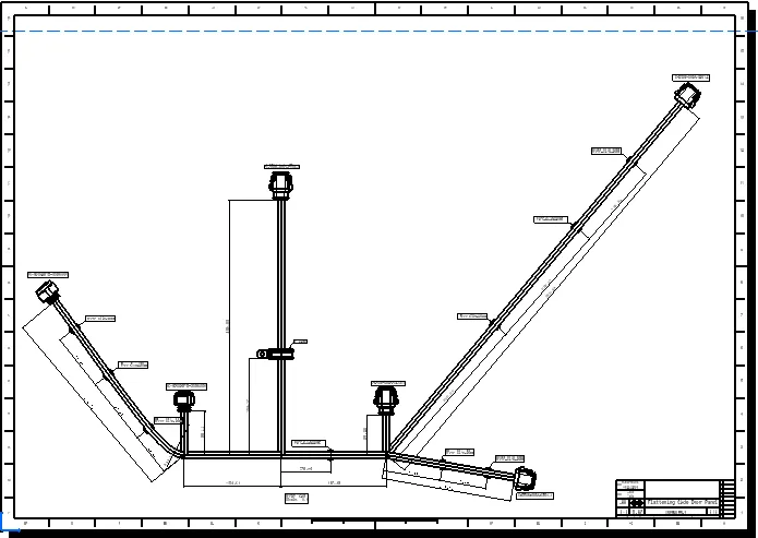
View Creation: Use the Front View command and select a flat surface in the Assembly Wiring Flattening Product. The flattened drawing (Side Door Panel Drawing-1) will be created.
Details: Add the Bill of Material (BOM), layout, dimensioning, and labels for connectors and clips to the drawing.