Project 1
Wiring harness Design Project:-
AIM: Route the Wiring harness on Given Engine and Prepare flattened view drawing in CATIA V5. Application of all Packaging rules, Industry best practices studied in this course shall be demonstrated in design. Apply Protection coverings as required.
INTRODUCTION:
A wiring harness is a system of insulated conducting wires bundled together wihch are used in electrical systems, motor vehicles, automobile, aircraft etc. Wire harness engineering is the development process of an electrical foundation for the safe and reliable distribution of power throughout a system. It forms the foundation of reliable, cost-effective and successful product design and manufacturing
ENGINE Wiring Harness
An engine wiring harness is an organized set of wires, cables, connectors and terminals that controls a vehicle’s electrical system. Engine wire harnesses relay electrical power and control information to outlying components such as:
- Alternators
- Audio Systems
- Batteries
- Blower Motors
- Computers
- Fuel Injectors
- Fuses
- Windshield Wipers
- And everything else that is controlled electrically that you can find in a vehicle
How Does Engine Wiring Harness Works?
An engine wiring harness is constricted wires, cables, terminals, and connectors controlling a vehicle’s electrical system. It relays electrical power and control information to components such as batteries, alternators, fuel injectors, fuses, audio systems, blower motors, fuel injectors, and computers. Wire harness companies customize it for every location, application, and design it interconnects.
They wire the electricity produced by the engine to the various parts and sensors. It is created using the High-Temperrature plastic or rubber parts because the engine heats up a lot and that can cause the engine harness to melt over time.
DESIGNING:-
- We have to dowload the Engine CAD file and all the necessary connectors required for this model.
- Then we have to electrically define all the connectors.
- Then in a new product file we load the Engine data and create a context assembly and a Geometric bundle.
- We then place the connectors in place and start routing the wiring harness.
- Then we apply protective covering to the bundles.
- At last we flatten out the wiring harness for the Drafting.
ELECTRICALLY DEFINED CONNECTORS:
- After downloading the connectors we have to electrically define them.
- First we go into the part workbench and then load the .igs or .stp cad file of the connector.
- Then we go and create points and axis system.
- Then switching the workbench to Elctrical Part design, we define the connector.
- After that the connector connection point, cavity connection point and the bundle connection point is defined and the connector is saved.
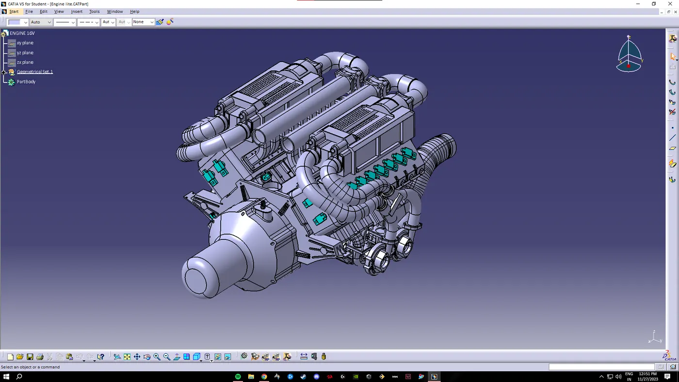
ENGINE CAD FILE:
The engine cad file is downloaded.
CONNECTORS:-
2-pole connector
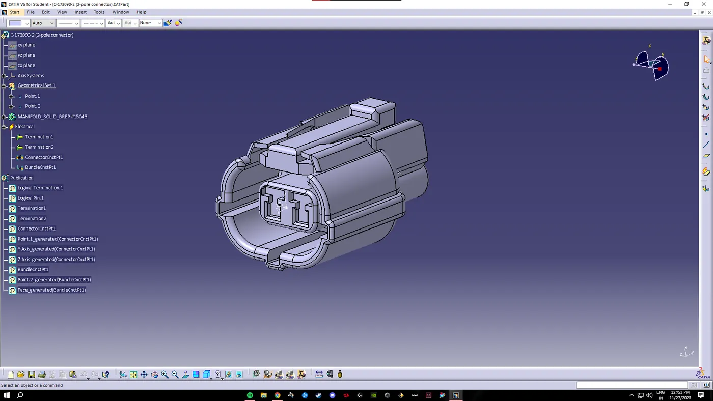
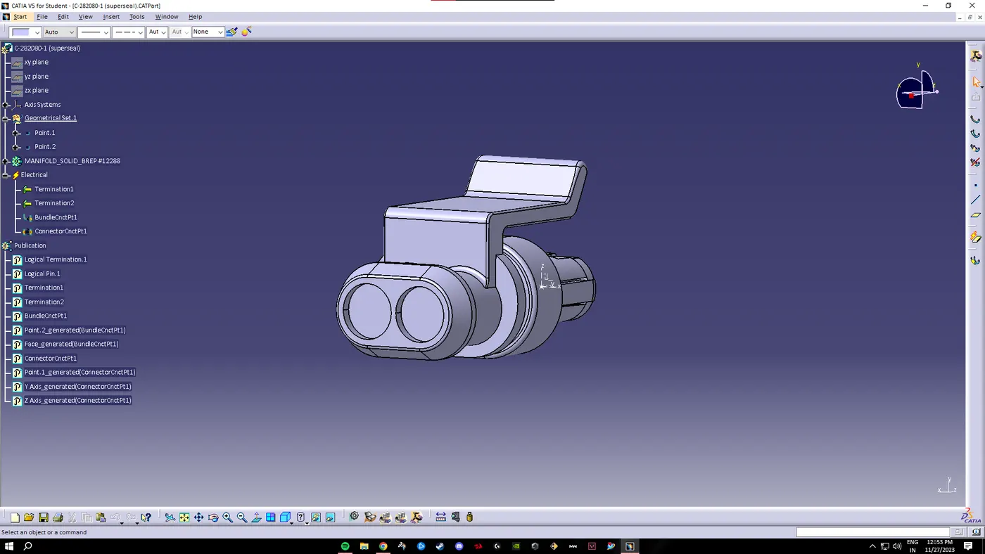
2 pole connector
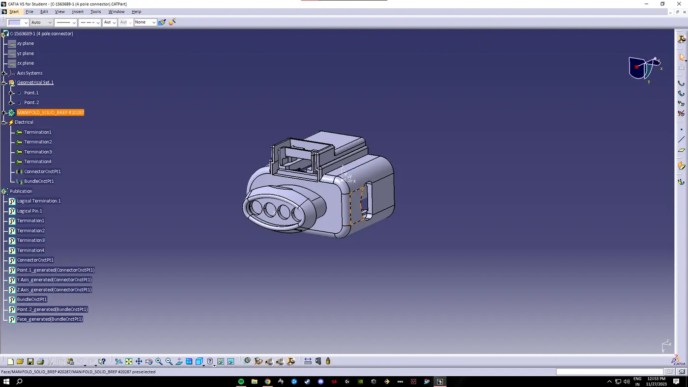
4-pole connector
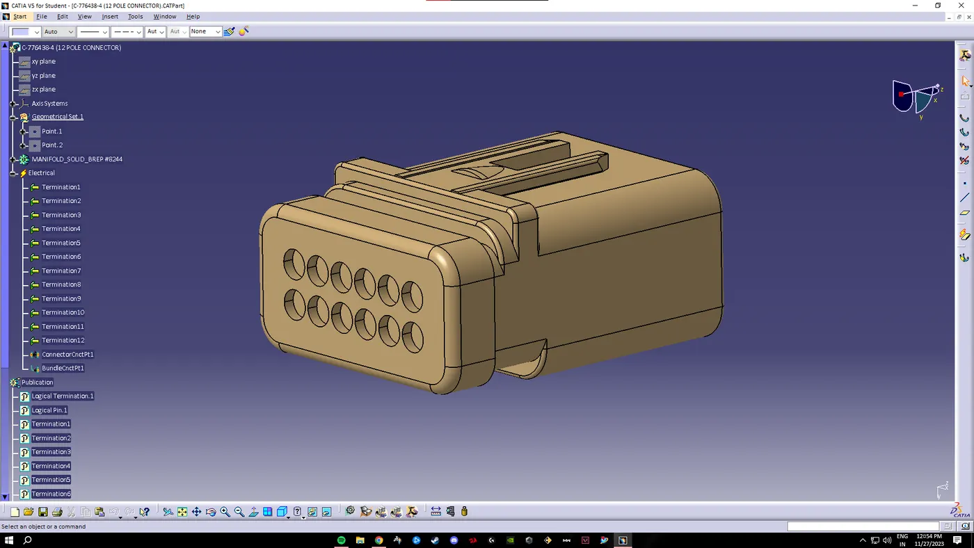
12-pole connector
PLASTIC CHANNEL:-
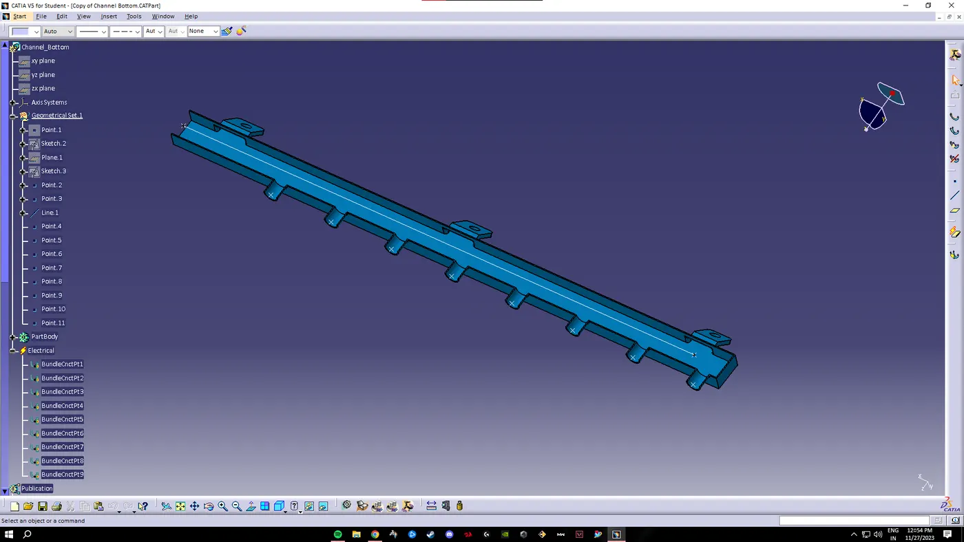
We download the plastic channel and create a channel symmetry file as it needs to be placed both sides of the engine block. We then create a main curve in the middle of the plastic channel for the routing of the wires. Then we go to the elcetrical part design workbench and create bundle entry and exit point for the main wiring harness branch. After that we create 8 fifferent bundle entry points according to our channel and also define them.
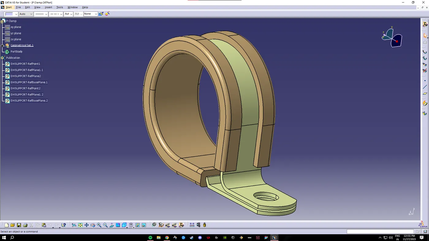
P-Clamp:-
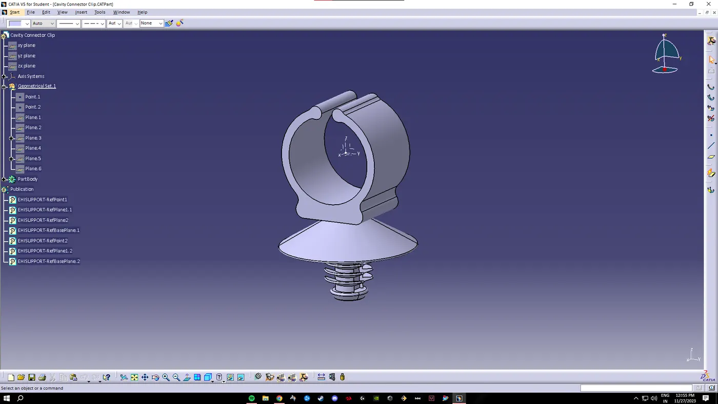
Cavity Connection Clip:-
Creating Assembly:
We create a new product file and inside we load the engine cad file. Then we again add a new product file and name it as geometric bundle where we place all the elctrical components. Then we define the geometric bundle electrically and start placing the connectors in it.
Adding the Fuel injector sensors:-
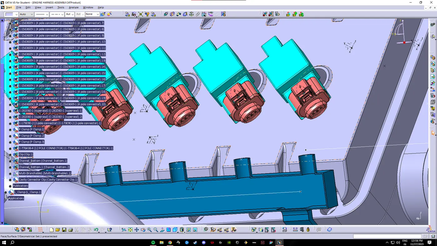
We add the 4-pole connectors by using copy paste and place them at definite positins by using the 'smart move or compas" option.
Adding temperature sensors, coolant sensors, position sensors:
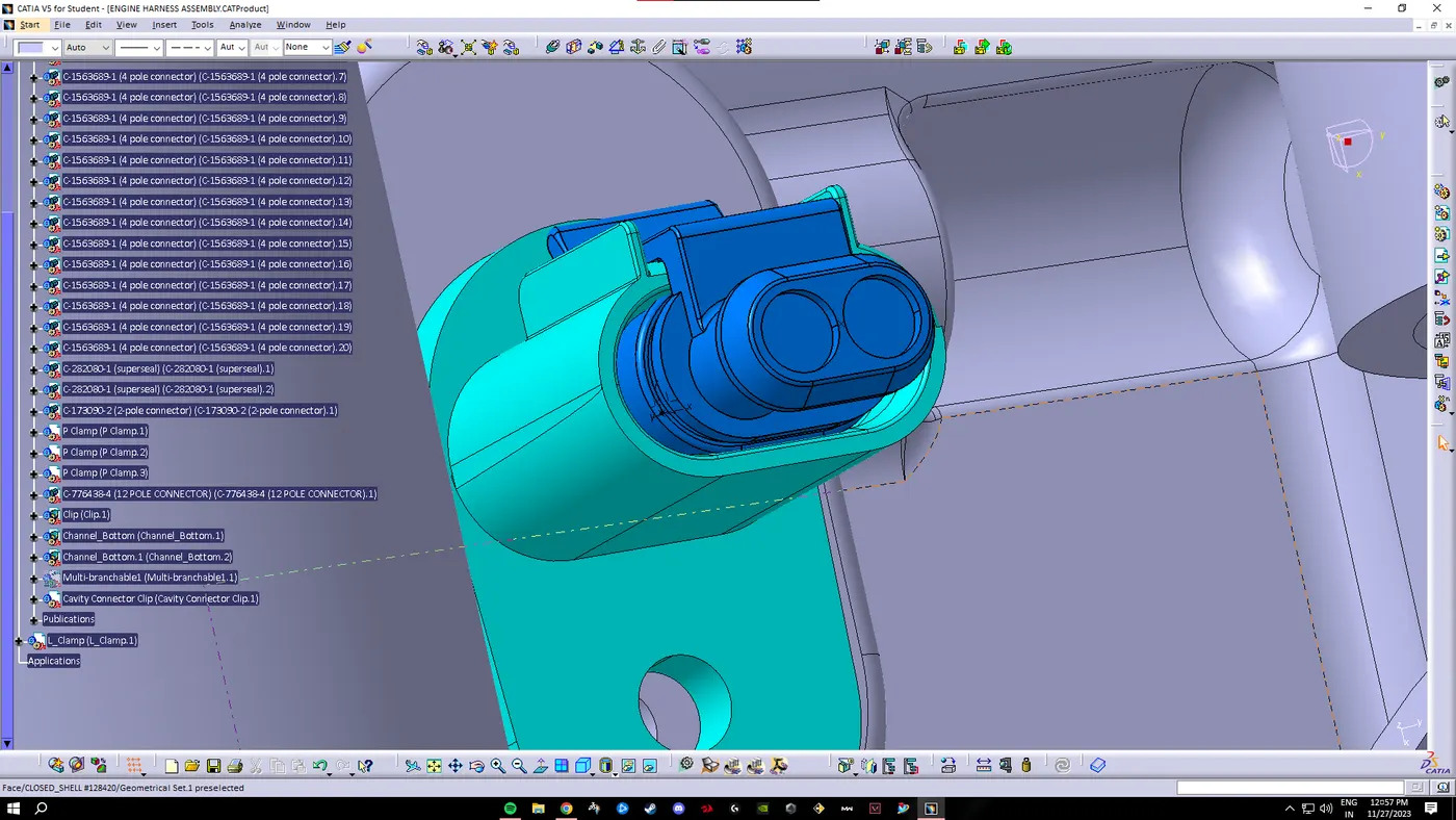
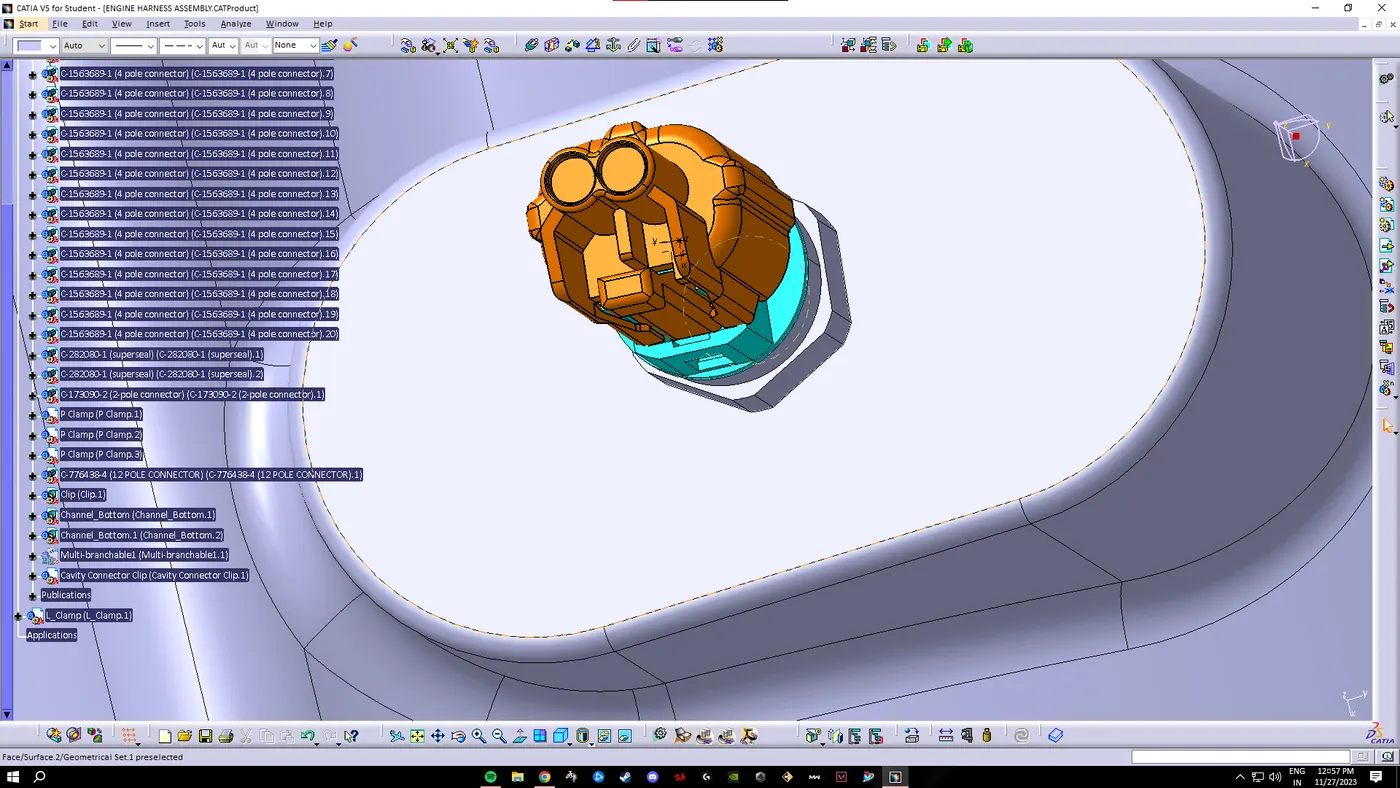
We add the 2-pole connectors by using copy paste and place them at definite positins by using the 'smart move or compas" option.
Adding L-Clamp support and Interconnection sensor:-
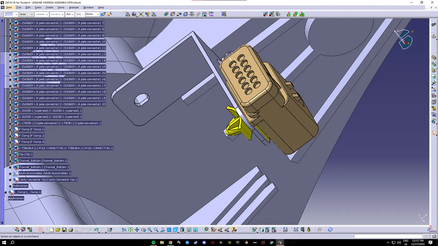
To add the L-clamp support we do not place it inside the Geometric bundle as this is a sheet metal bracket which ahs to be produced by the manufacturer who is developing the sheet metal parts.
Also the P-clamp should be placed in a way so that there is no rattling noise, no physical damage to the connectors and the wiring can take place seamlessly.
We add the 12-pole connector by placing it at definite positins by using the 'smart move or compas" option.
Adding P-clamps and furr tree clips for the routing:-
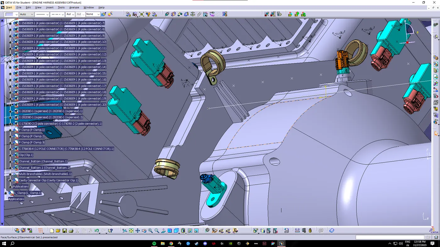
We then add the p-clamps and place them at optimal positons by following the packaging rules. This means that by placing the p-clamps we are avoidng the fouling of the wiring harness which could have taken place if these were not added. The p-clamps and furr tree clips are added to the engine block by fasteners.
Adding plastic channel for the routing:-
We add the channel palce it carefully so that there is enough space to guide our wires and thus provide clearence which we could not have acheived if we have used P-clamps.
HARNESS ROUTING:-
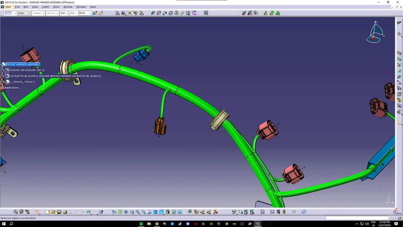
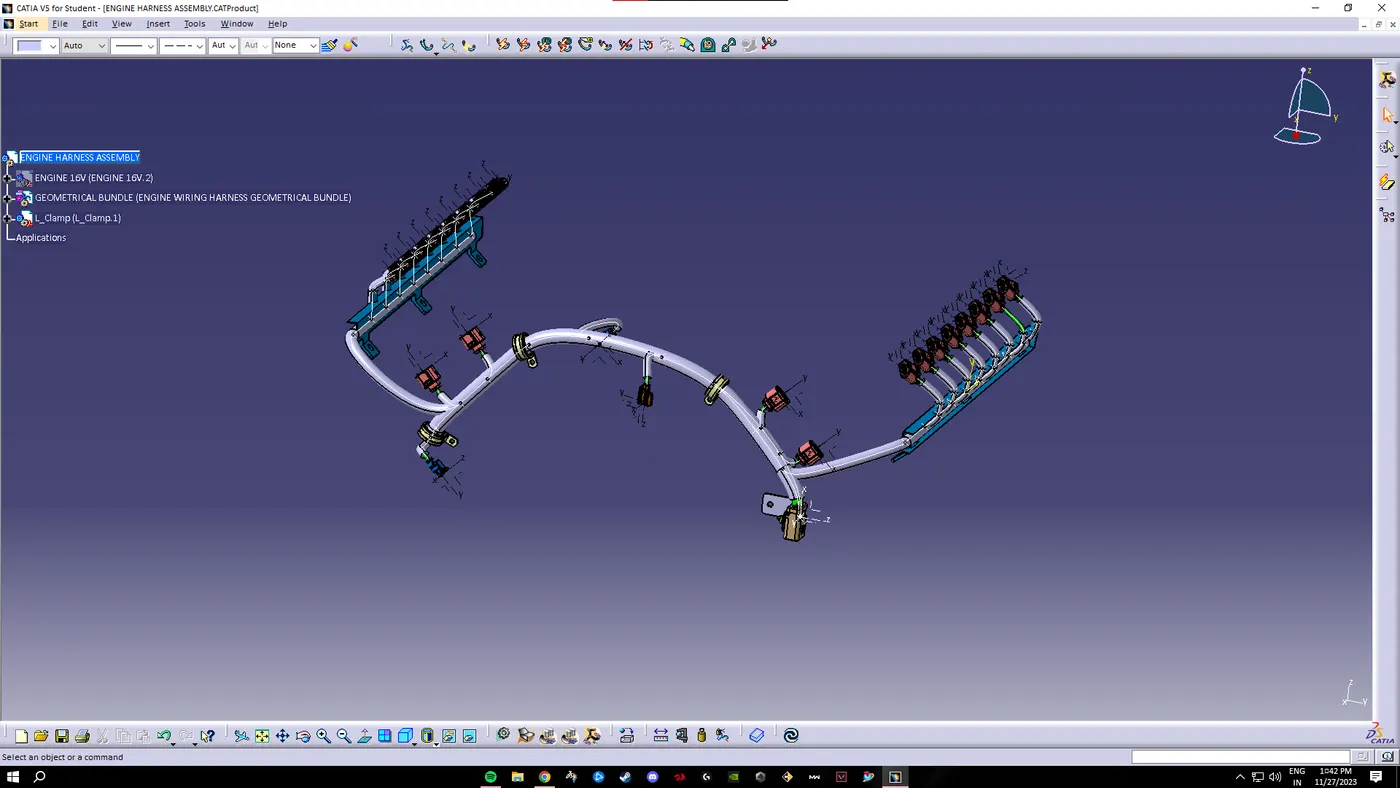
We now define our Geometric bundle and create a Multi-branchable bundle. Then we proceed to our routing. For the channel we select the external curve option to acheive a seamless channel.
FINAL ROUTING:-
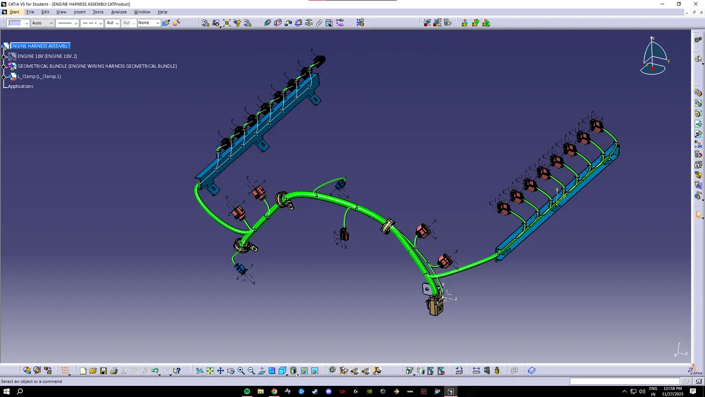
Our routing is now complete.
ELECTRICAL CONNECTIVITY CHECK:-
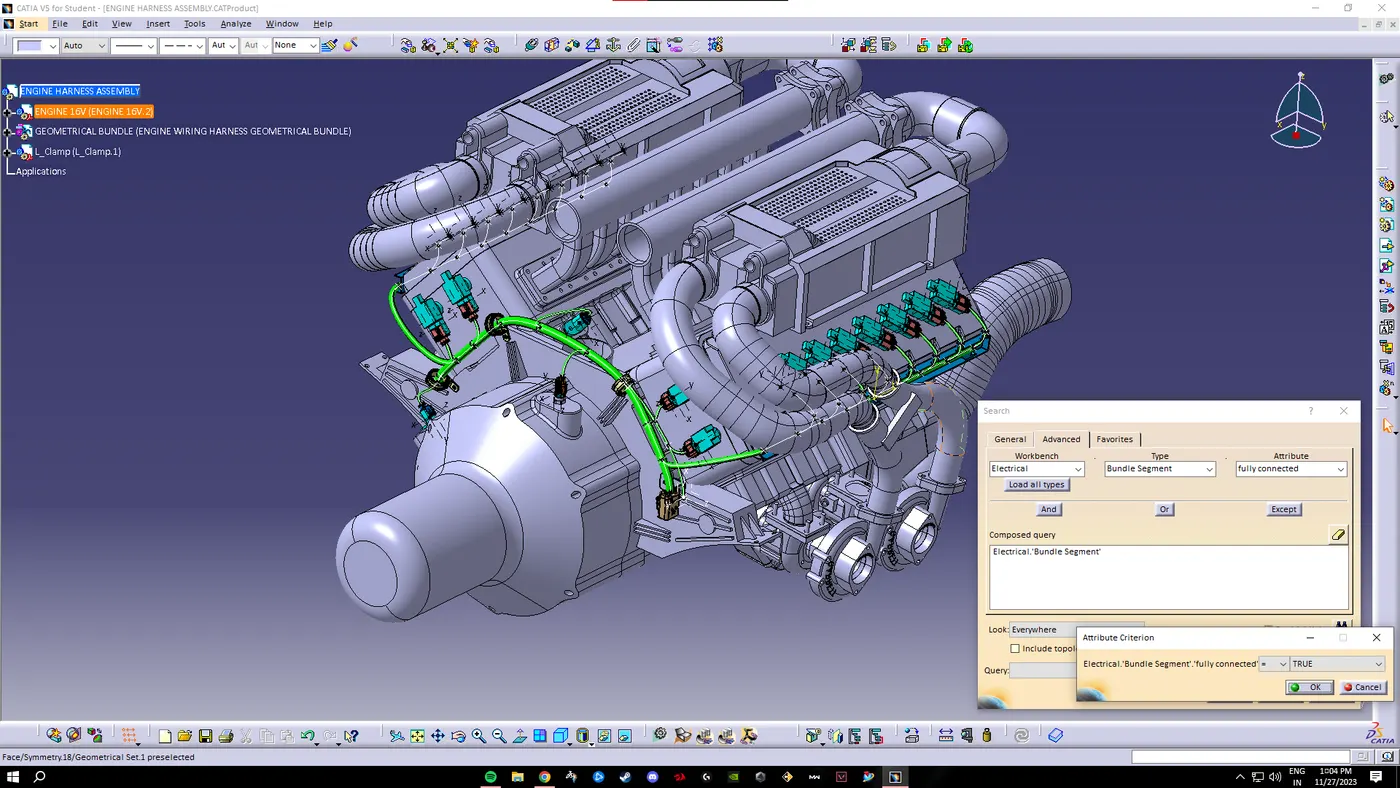
After completing the routing of the wiring we now have to check if the the wires are electically connected. For this we go to search option, the go to advanced then select workbench as electrical, type as bundle segment and attribute as fully connected.
We find that our routing is 'true' meaning all our wires are elctrically connected.
Adding Protective Covering:-
After completing the wiring harness routing by following the packaging rules, we provide Protective covering to the wires. Slit-COT tubes, cotton tapes are added.
WIRING HARNESS FLATTENING:-
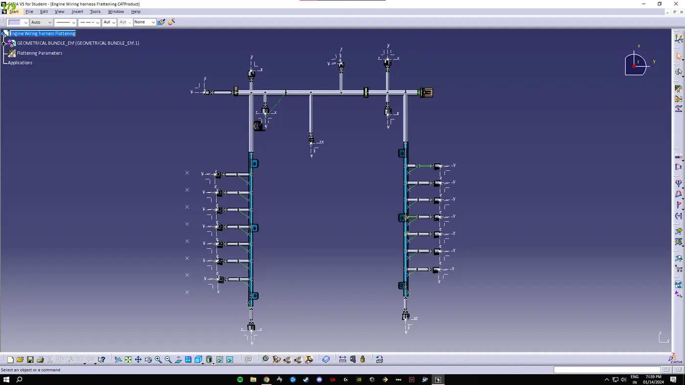
Our Engine wiring Harness is complete. Now we have to flatten the routed wiring. For that we need to move on to Electrical Flattening workbench. To create the flattened harness we need to add a new product and switch to electrical harness flattening parameters and then extract the geometric bundle from the wiring harness context product file. Then we need to select all the bundles and flatten the entire geometric Bundle.
Engine Wairing harness drawing:-
After the flatenning is done, we open the drwaing workbench and place the flattening in the drawing.
CONCLUSION:- Hence, the Wiring harness on Given Engine and the flattened view drawing in CATIA V5 is completed.