Project 1
WIRING HARNESS OF ENGINE - PROJECT 1
AIM:
Design and develop the wiring harness on Given 6 Engine and Prepare flatten view drawing in CATIA V5.
OBJECTIVE:
- To define all the connectors electricallyy and save it in catalogue.
- To place all the conectors and cavities at the required position.
- To place P clamps and Fir tree clips at the required position by the following the packaging rules.
- To create the wire harness routing as per required and create branch points wherever required and also by following the packaging rules.
- To create the wire harness Flattening of the above routing.
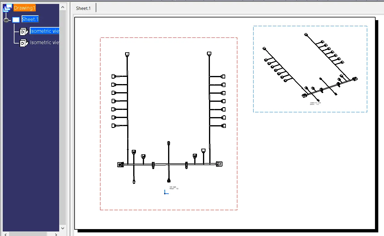
- To display the flattened view in the drawing sheet.
DESIGN METHODOLOGY:
STEP 1: Create a product file where the part and product file will be assembled.
STEP 2: Create another product file as Geometric Bundle where connector and final routing is saved.
STEP 3: Add the Engine , Geometic bundle in a single Product file.
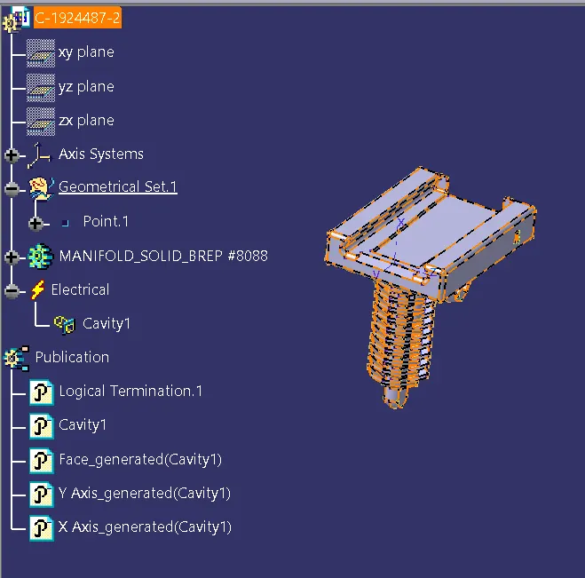
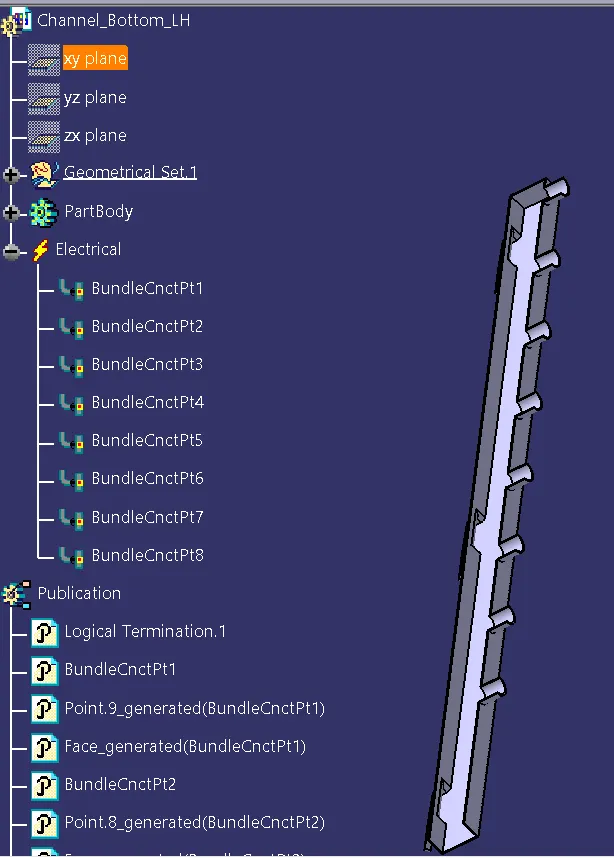
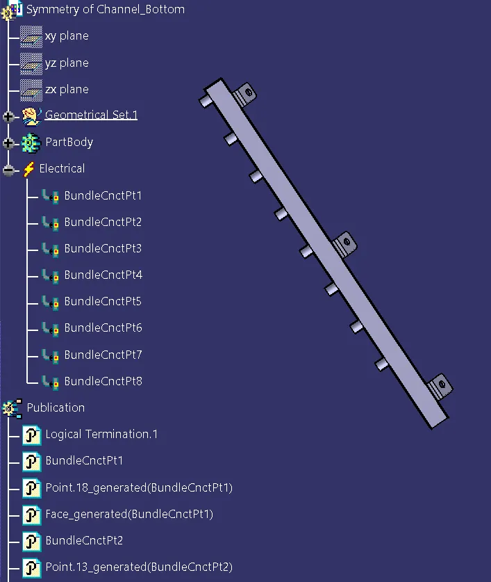
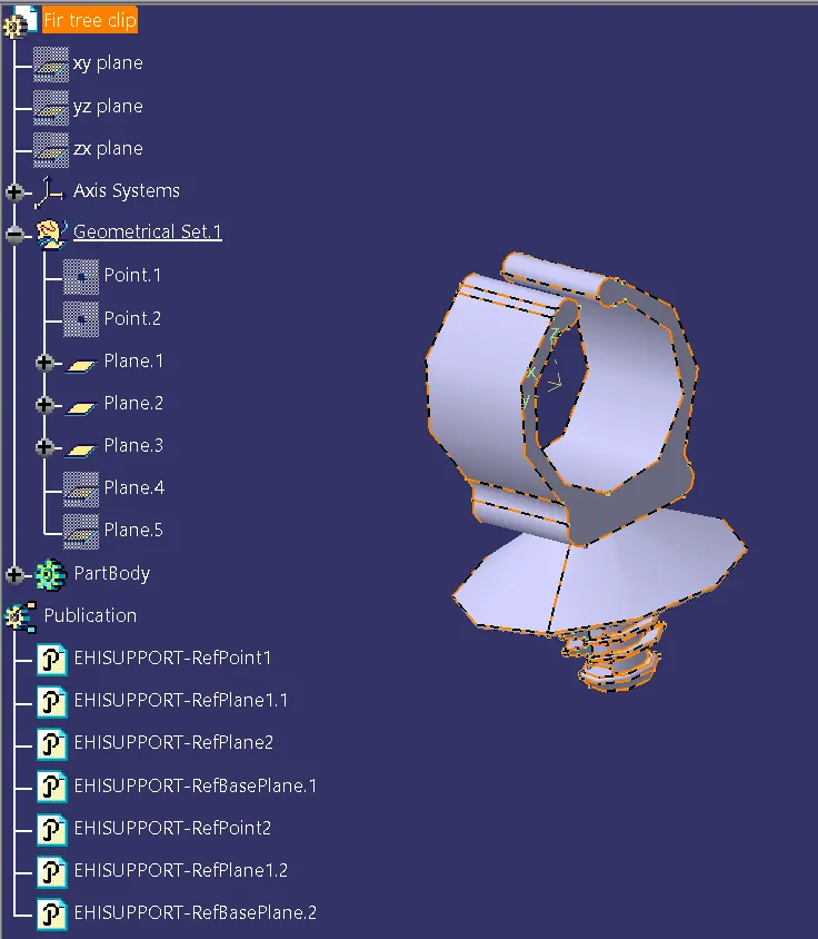
STEP 4: All the connectors, clips, clamps and channel part are to be electrically defined and added to the catalogue.
ELECTRICALLY DEFINED CONNECTORS:
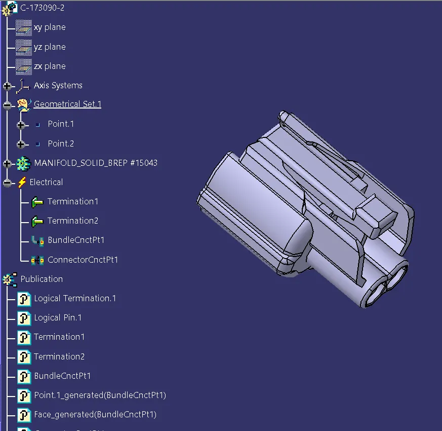
1. C-173090-2:
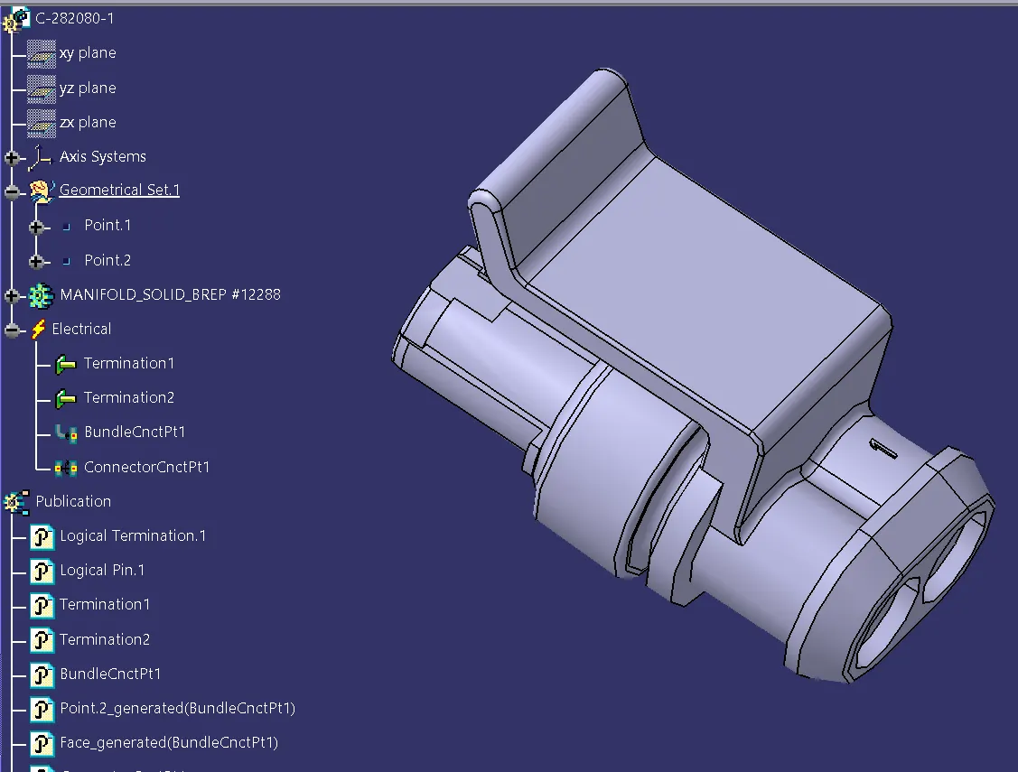
2.C-282080-1
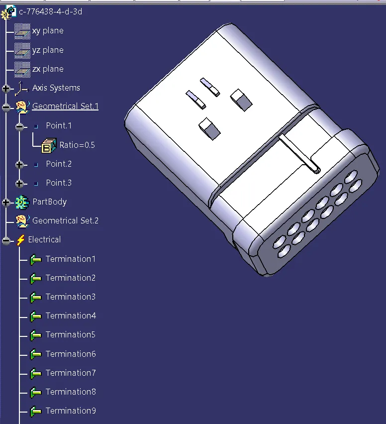
3. c-776438-4-d-3d:
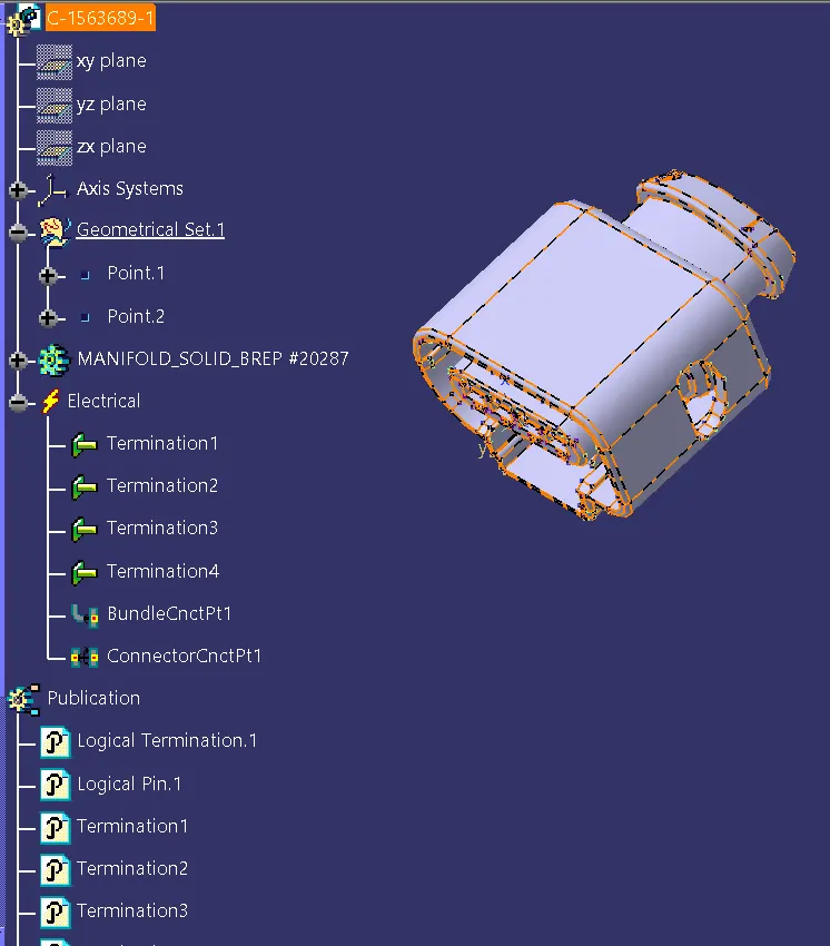
4. C-1563689-1:
4. C-1924487-2:
5. channel bottom LH
6. channel bottom RH
7. Fir tree clip:
Step-5:
Adding all the required file to the Geometric bundle and positioning them using "SMART MOVE" and " MANIPULATION TOOL"
PACKAGING RULES CONSIDERED DURING WIRING HARNESS ROUTING:
- P-clamp, fir tree clips and cavity are added to the Geometric bundle as they are electrically defined and are part of wiring harness routing and should be provided with the wire bundle package.
- Minimum bundle length of 50mm to be maintained.
- Slack should be provided enough so the wiring harness doesnt get damaged due to engine rocking or idle conditions.
- Wiring harness should be done by considering easy manufacturing and serviceability.
- Additional slack can be provided depending upon the surrounding and bending requirements.
- avoid excess slack by minimising the slack or by giving zero slack wherever possible.
- Every connector should be given with a slack so that there will be no tension on wire bundle.
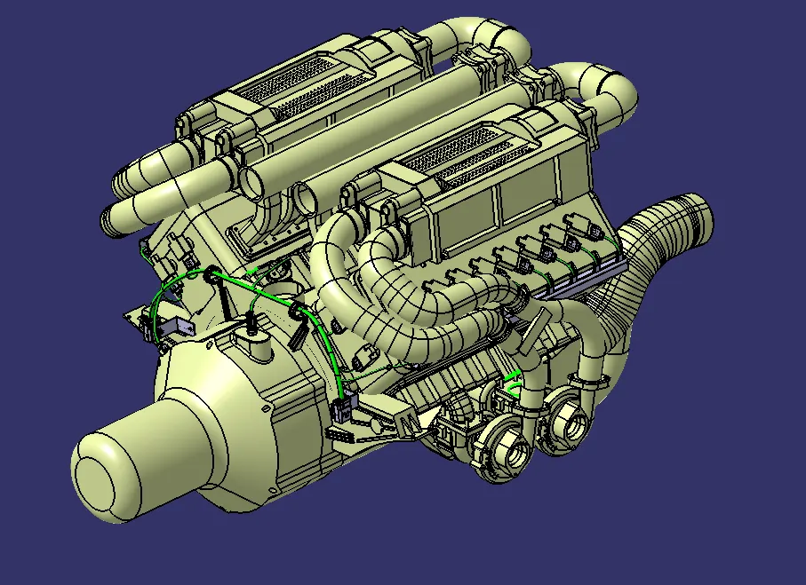
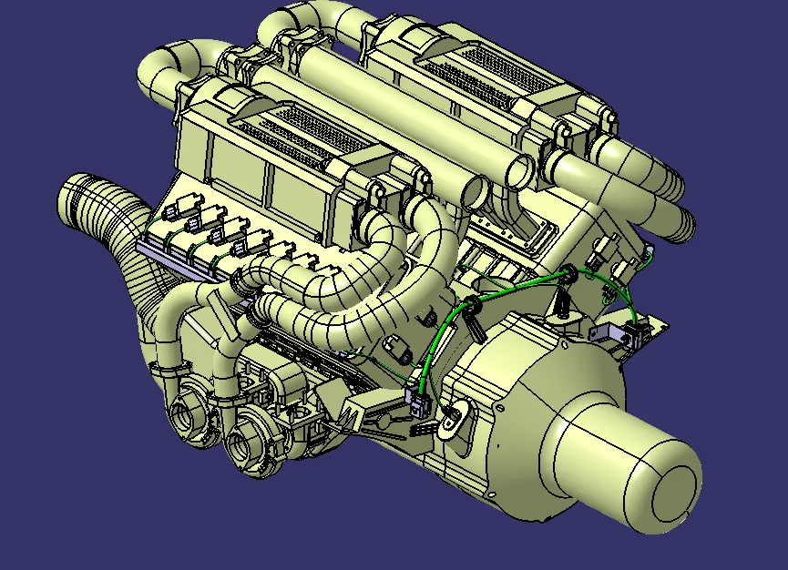
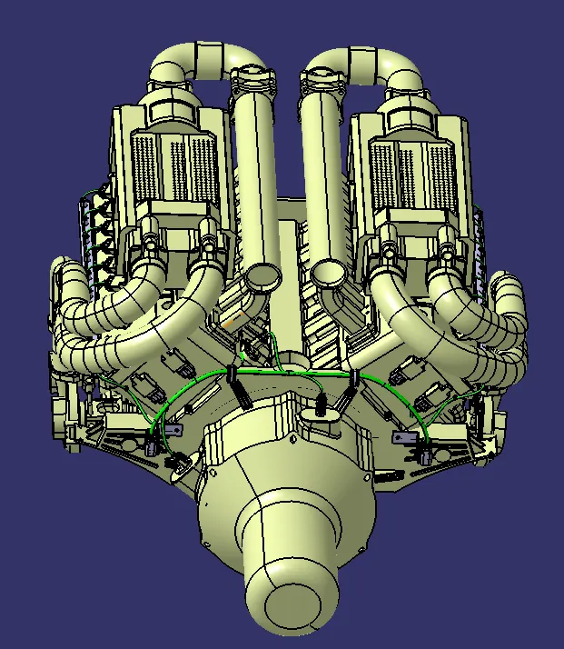
FULLY ASSEMBLE AND ROUTED IMAGE:
STEP 7:
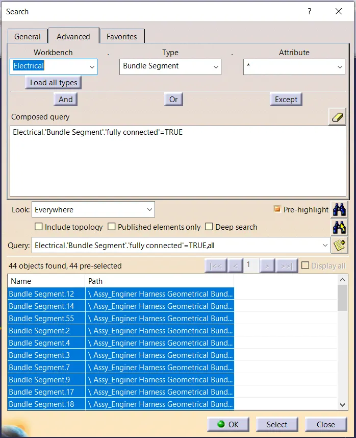
Once routing is finished. check for routing connectivity
STEP 8:
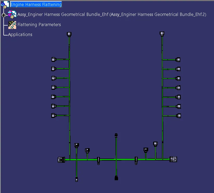
WIRING HARNESS FLATTENING:
To create the wire harness flattening we need to create another product file and navigate to Electrical Harness Flattening workbench.
In the workbench define the Harness Flattenig parameters anad extract the geometrical bundle from the wiring harness product file.
Select the branches and flattend the entire geometrical bundle.
The bundle can be rotated and rolled with a proper radius in or to fit the drawing sheet.
STEP 10:
After the Harness if flattened in the respective product file and workbench is flattened and represented in drawing sheet.
CONCLUSION:
From the above project the routing of wire haness on a Engine, flattening of the wire routing, packaging rules to be kept in mind during wire routing, conversion of flattene product file to CATPART file are learned.
FILE ONE DRIVE LINK:
https://drive.google.com/drive/folders/1qu2N2LzC-pJcTuWhiFeu-FNz1jkpth16?usp=sharing
NOTE:
1. AS THE FILE SIZE IS MORE THAN 80MB EVEN IN ZIPED CONDITION. UPLOADING AS ONE DRIVE LINK.
2. UPLOADED ZIP FILE, BUT IT DOESNT HAVE THE ENGINE FILE. KINDLY USE THE