Hood design-Week 2
AIM:
Design Hood Outer Panel, Inner Panel and the necessary reinforcements by following the Master Section mentioned with the Design parameters.
HOOD:
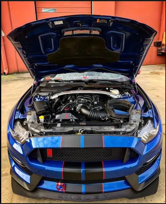
Hood or bonnet covers the engine in the front and simulataneously maintaining the look of the vehicle. They are basically made from steel and aluminium.
In front engined cars the hood is basically hinged to provide easy access to the engine during servicing and regular maintainance.
The hood movement is maintained by hinges and locking is done using striker in hood and locking mechanism in the car body.
HOOD DESIGN:
Before starting with software design, there are many things to be consider.
The opening angle and mininum height to be maintained in open position are caluclated based on the height of the average person in the region where the car is gonna be sold. As the average person height varies from region to region.
The pedastrian safety - while designing a car not only considering the safety of the passenger but also considering the minimal safety of the pedastrians of all ages are important to gain the NCAP rating.
LATCH TRAJECTORY:
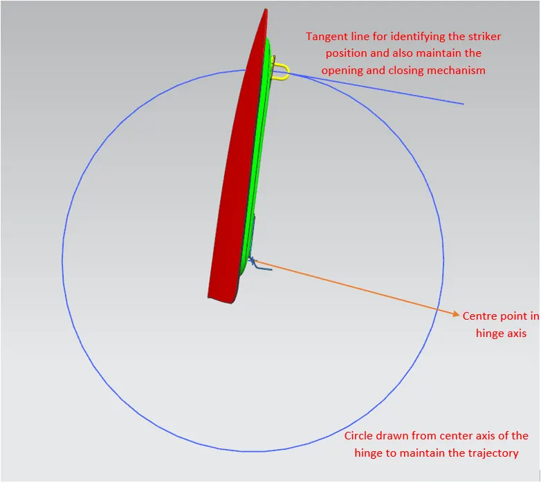
The Latch Trajectory is used to maintain the opening the closing mechanism without any hinderance and making it longlasting and also maintaing the ease of opening and closing operations.
MASTIC DATA:
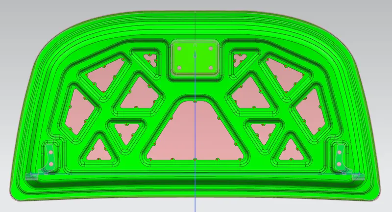
Mastic points are places where gum is pasted and minimum gap maintained for mastic points is 5mm. These mastic gums are soft until they are heat treated, once they enter the furnace they get hardened. The below image has red dots representing the mastic points where the gum is going to get pasted.
DEEP DRAWING:
Deep drawing is one of the sheet metal forming process mainly used in automobile for maintaing the strenth and reducing the weight.
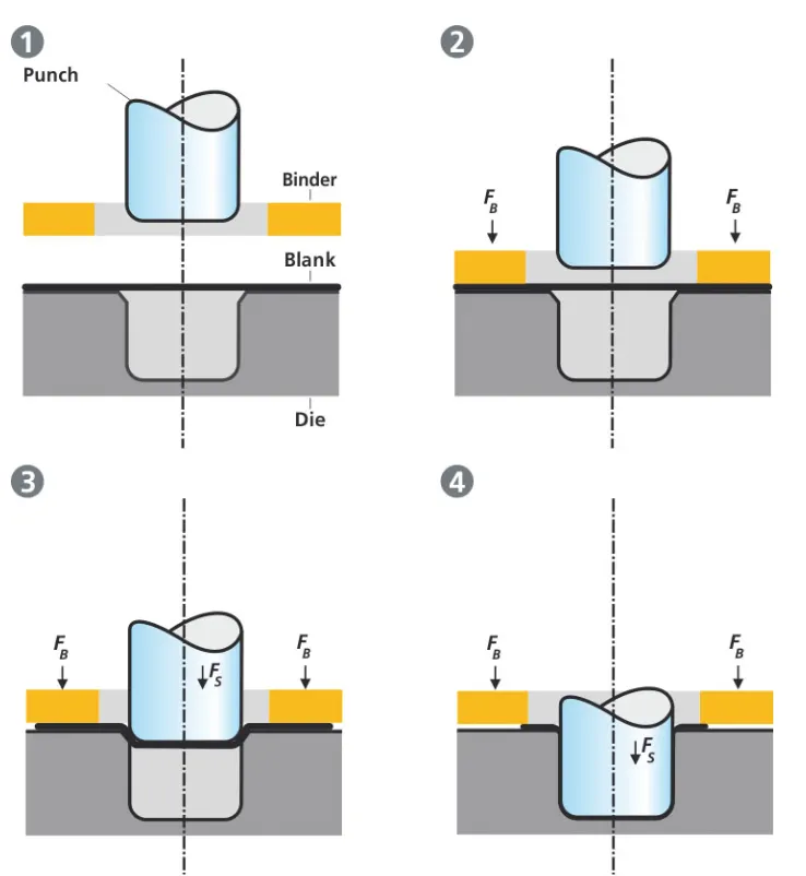
Deep drawing of sheet metal is performed with a punch and die. The punch is the desired shape of the base of the part, once drawn.
The below imae shows the simple sheetmetal drawing operation and it can be done for different shapes as per our need.
HEMMING:
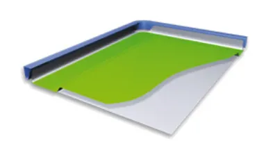
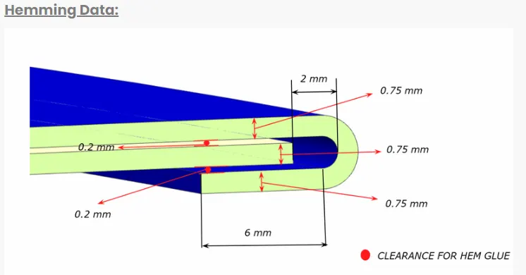
Hemming is also a forming operation where the edges of the sheet metal are folded in to avoid shard edges and also connecting parts together.
There are two types of hemming
1. Conventional die Hemming
In conventional die hemming the flange is folded over the entire length of the hemming tool. It is widely used in mass production they are folded in steps based upon the flange specifications.
2. Roll Hemming
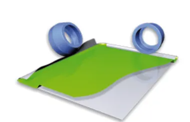
In Roll hemming the hemming roller guided by a robot is used to fold the flange. The hemming operations is carried out by following several steps by minimally increasing the folding angle.
MODELING PROCEDURE IN NX-CAD:
INPUTS:
Hood Thickness Information
- Outer Panel Thickness = 0.75mm
- Inner Panel Thickness = 0.75mm
- Reinforcement Thickness = 1.5mm
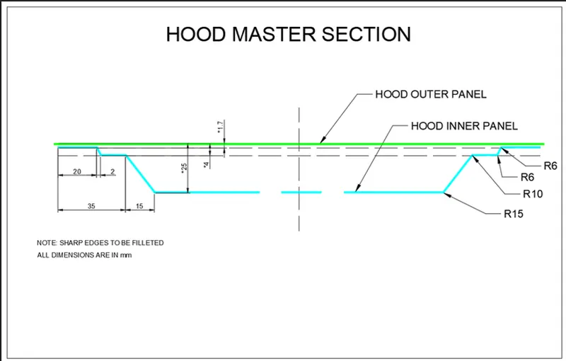
HOOD MASTER SECTION:
CLASS A DATA:
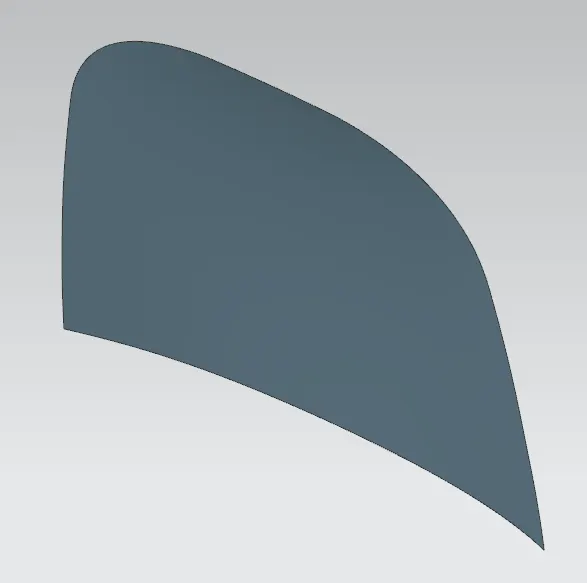
The class A surface are provided in the form of a .step or .igs files.
PROCEDURE:
The given class A surface are imported into the part file and the first model will be a HOOD INNER PANEL.
The given class A surface is offseted to zero mm and parent file is hided, The offseted surface is split into two halves symmetrically using a datum plane as the LH and RH design is going to remain the same modeling on one side and mirroring it will be a best option to save time and reduce feature used in design.
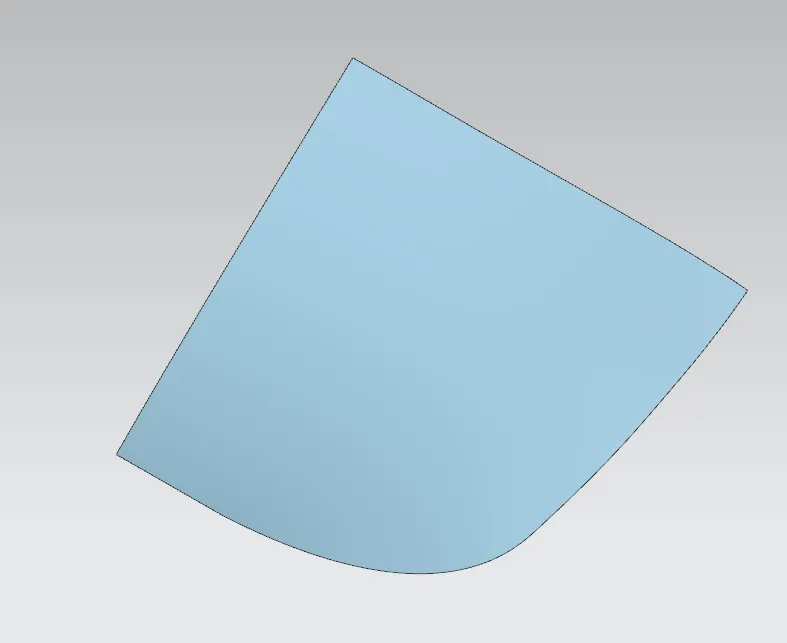
The next offseted surfaces are created as per the master section using offset surface, offset in face curves, trim sheet, through curves and law extension commands.
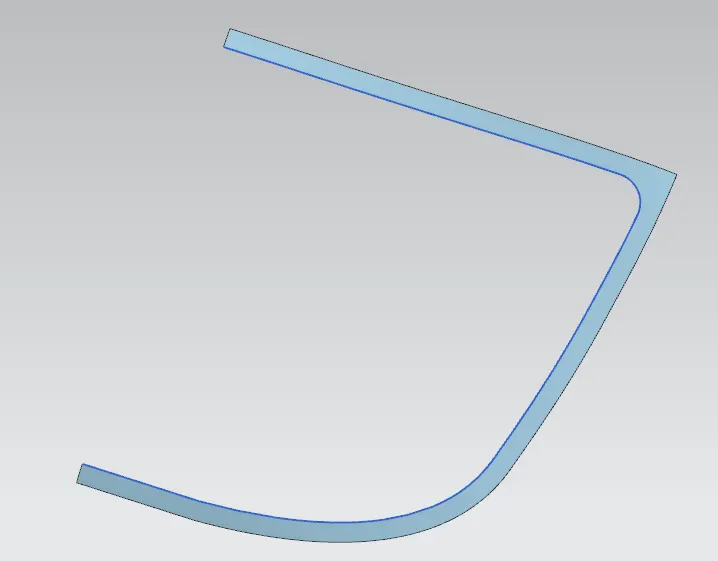
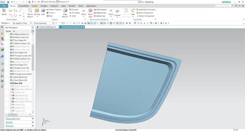
The next emboss in opposite direction to the prior emboss are to reduce weight and maintain mastic points and mastic maximum distance of 5mm.
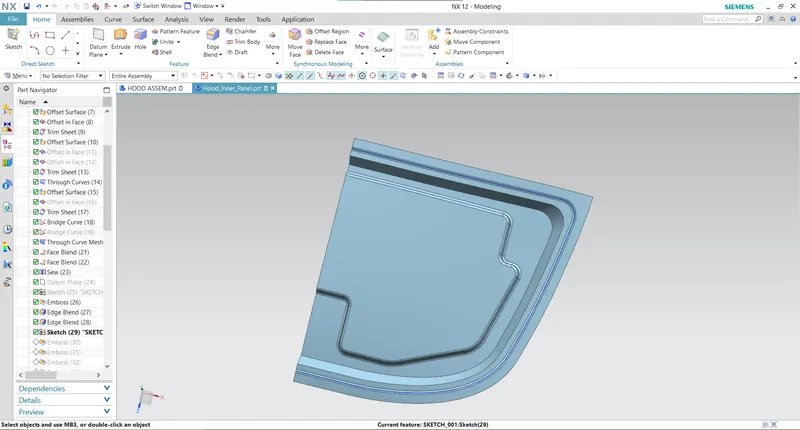
The mastic points are created to fix the outer and inner panel together using mastic gum.
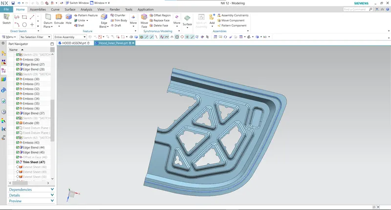
After completing the mastic points and trim commands. the edges of the split side are extended uption 5mm and again trimmed using datum plane. This procedure of extending and splitting is followed to avoid the errors in further steps.
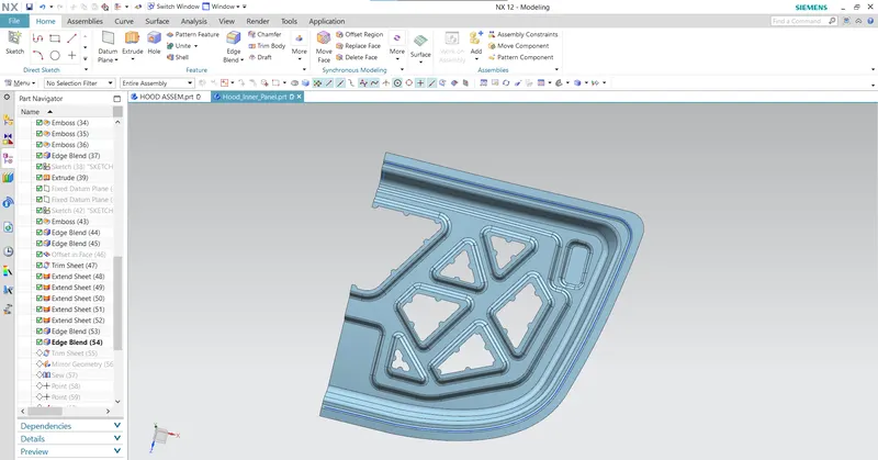
Then by mirroring and using sew command to get the other side of the inner panel.
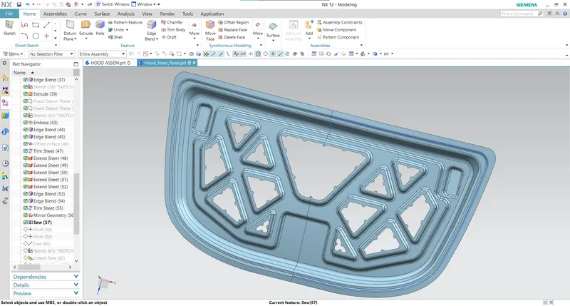
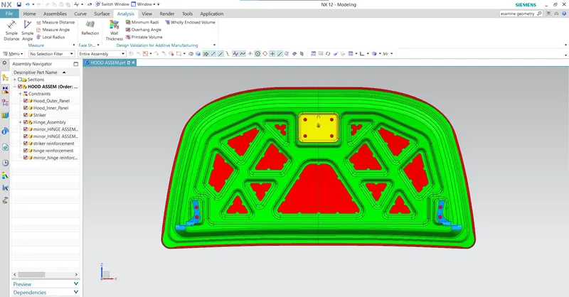
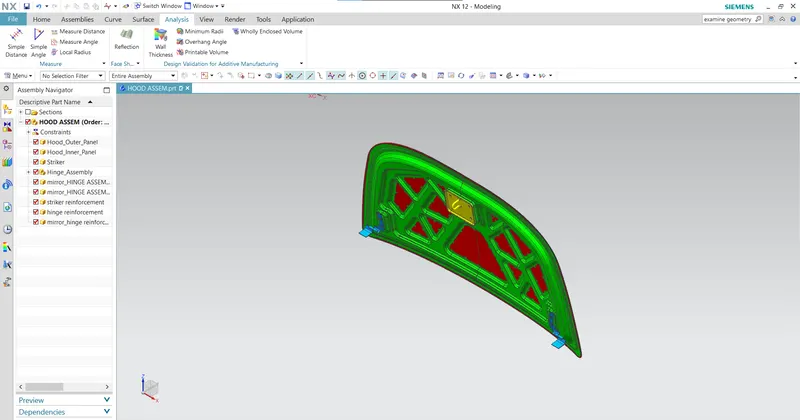
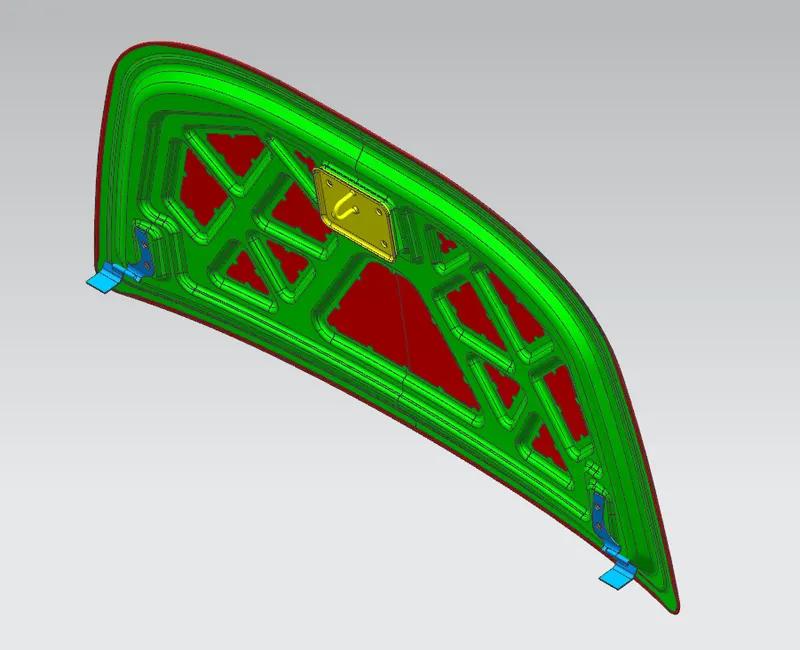
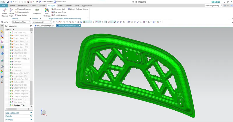
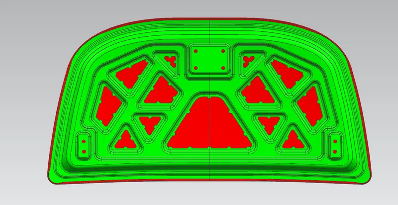
After completing the sew command examine geometry operation is carried out to check for any gaps and other errors.
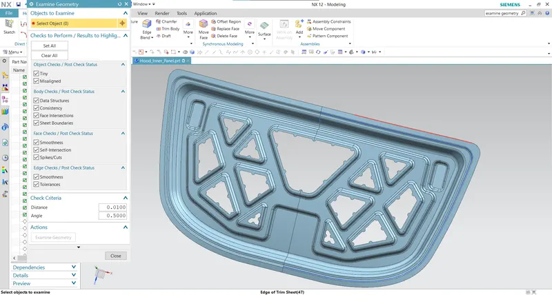
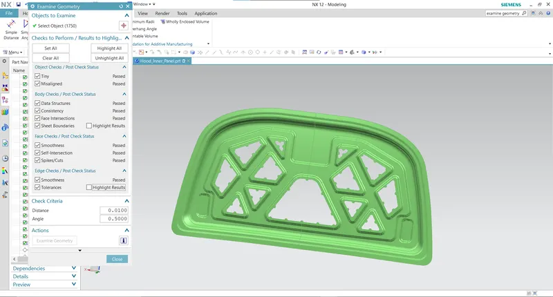
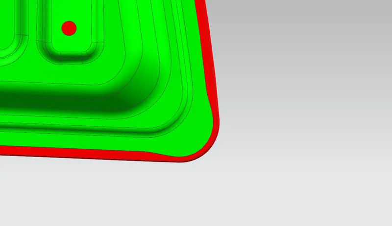
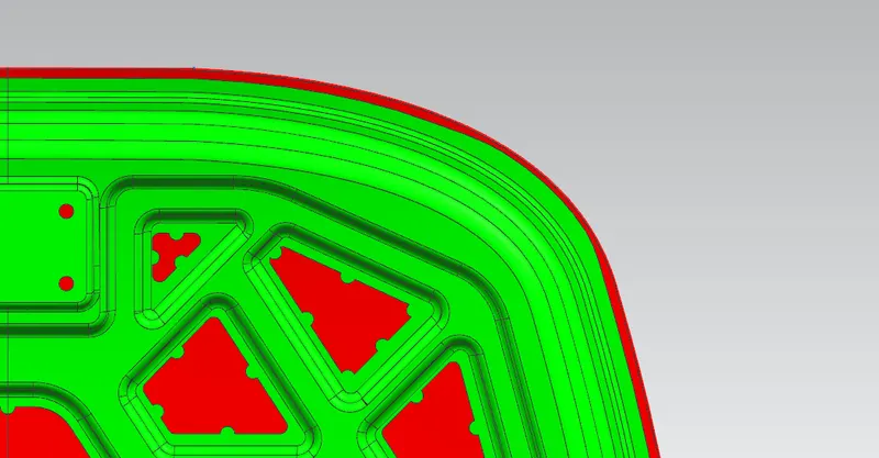
Here the above image shows the geometry check is over and the green colour represents its ok. if any red lines and points appears it represents some errors in the model.
HINGE PLACEMENT:
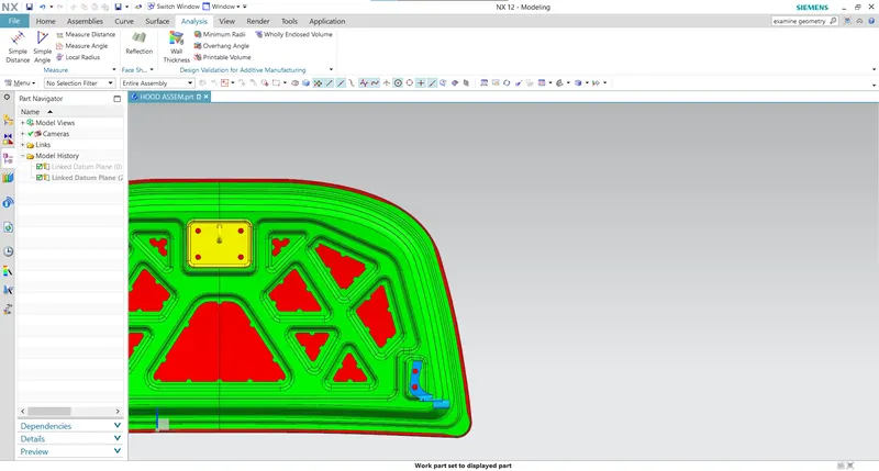
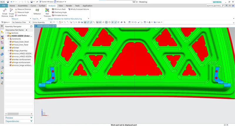
The first hinge is placed in the assembly by importing the inner panel and fixing the inner panel to the assembly datum plane. the other hand hing is created by using the mirror assembly command and maintaining the associative properties in the parent hinge file.
LATCH ATTACHMENT:
The latch or striker positioning is done by drawing a line to the two hinge centre pivot point.
By sing the line as axis centre and a circle is drawn and corresponding tangent line to the circle is also drawn.
The tangential line shows the position of the hinge and the circle represnts the trajectory of the striker.
Using the same as reference, a line for striker hook is drawn and both are made to coincide and the position for the striker is located.
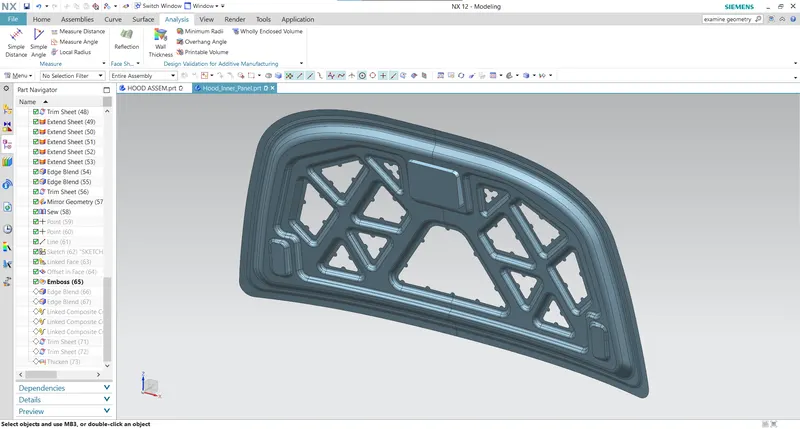
After this step the emboss for striker is created.
OUTER PANEL:
The outer panel is first offseted to the distance as per given value below inner panel by calculating the allowance and thickness and using law extension command and face blend (three faces) command hemming operation is done.
The corner reiles are maintained as per the given data.
FINAL HOOD DESIGN: