Project 1
Solution:
Q. No. 1 (a):
Rated Power (Prated)= 150kW
Rated Voltage (Vrated) = 120V
Nominal Cell Capacity = 3500mAh
Nominal Cell Voltage = 3.6V
Rated Current (Irated) = Prated/Vrated
= 150*103/120
Rated Current (Irated) = 1250A
Number of Celles in series = Vrated/Nominal Cell Voltage (assuming maximum voltage = rated voltage)
= 120/3.6
Number of Celles in series = 33.33
Case 1: Considering Number of Celles in series as 33
Total Battery Voltage = Nominal Cell Voltage*Number of Celles in series = 3.6*33
Total Battery Voltage = 118.8V
Case 2: Considering Number of Celles in series as 34
Total Battery Voltage = Nominal Cell Voltage*Number of Celles in series = 3.6*34
Total Battery Voltage = 122.4V
As the Total battery voltage in case 2 is higher than the rated voltage, number of cells in series is taken as 34
Number of Celles in series = 34 cells
Number of cells in parallel = Rated capacity/Nominal cell capcity
= 1250/3.5
Number of cells in parallel = 357.14
Case 1: Considering Number of Celles in parallel as 357
Total Battery Capacity = Nominal cell capcity*number of cells in parallel = 3.5*357
Total Battery Capacity = 1249.5Ah
Case 2: Considering Number of Celles in parallel as 358
Total Battery Capacity = Nominal cell capcity*number of cells in parallel = 3.5*358
Total Battery Capacity = 1253Ah
Number of Celles in parallel = 357 cells
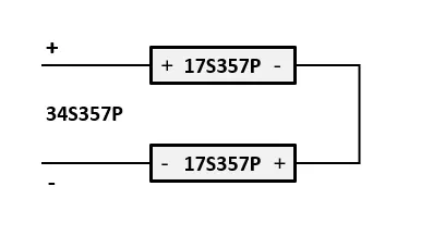
Therefore the battery pack configuration is 34S357P
Q. No. 1 (b):
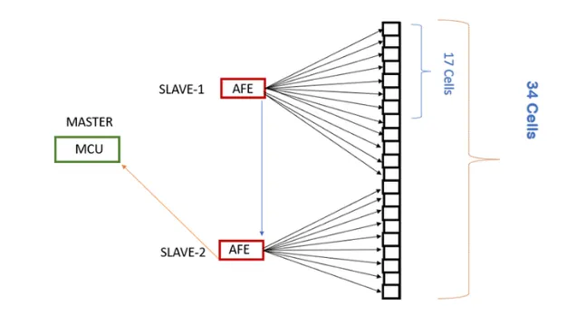
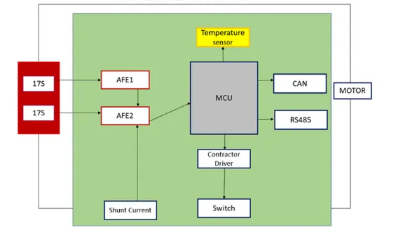
Master Slave BMS topology is used for this battery pack. In this architecture, there is typically one "master" module that oversees and controls the overall operation of the BMS, and multiple "slave" modules that monitor and control specific subsets of the battery pack. The master module communicates with the slave modules to gather information, make decisions, and ensure the proper functioning of the entire system.
The master-slave architecture allows for the scalability and modularization of the BMS, making it suitable for large battery packs with numerous cells. It also facilitates communication and coordination among different parts of the battery pack, ensuring safe and efficient operation.
Master Slave BMS Topology
Q. No. 2:
Simulink Model:
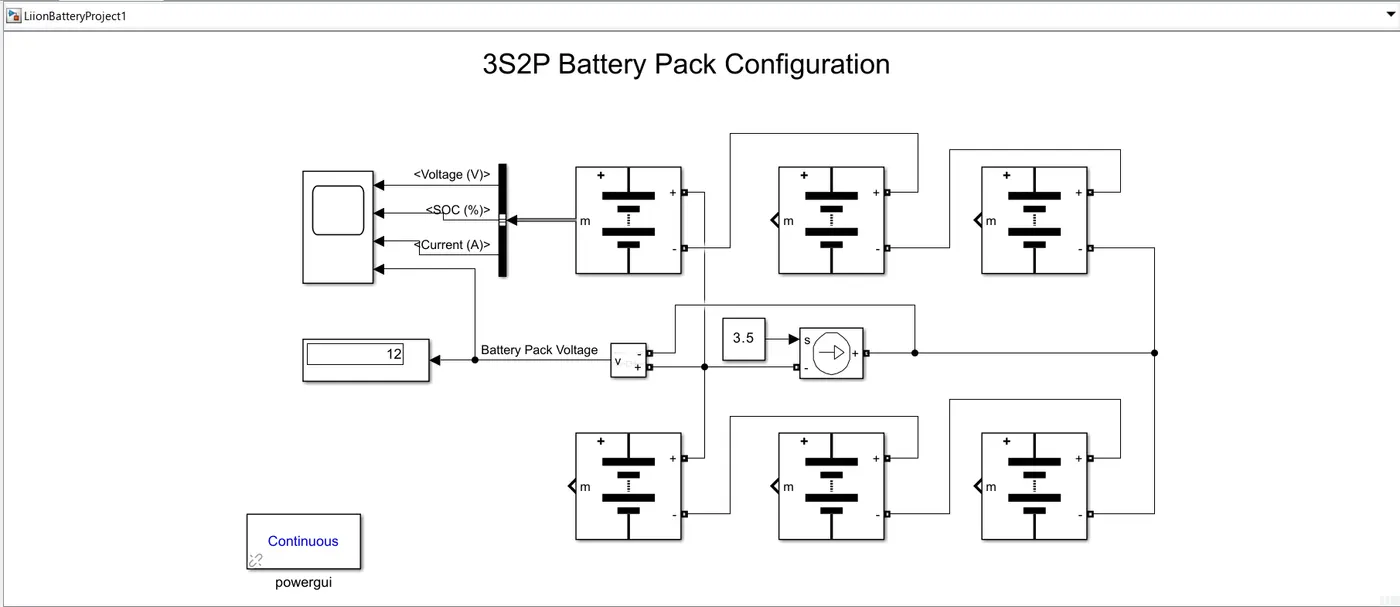
Blocks used:
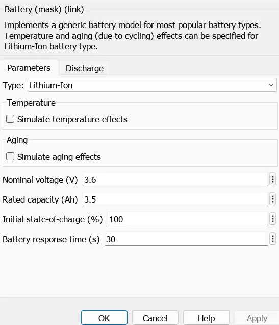
- Li ion battery (6)
- Bus Selector
- Powergui block
- Controlled current source
- Constant block
- Voltage measurement
- Scope block
- Display block
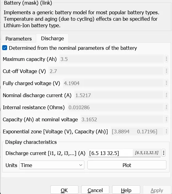
Cells are connected in 3S2P configuration (3 cells in series and 2 cells in parallel) as shown in the above figure. A Constant current source with the capacity of 3.5Ah (constant block) is connected to the battery pack acts as the load. The voltage measurement block is connected to measure the battery pack voltage. Scope is connected through the bus selector, which provides the voltage, current and SOC of the cell.
Theoretical Calculation:
Nominal voltage of cell = 3.6V
Capacity of cell =3.5Ah
Maximum voltage of cell =4.2V
Number of cells in series = 3
Number of cells in parallel = 2
Nominal Voltage of battery pack = no.of cells in series * nominal voltage of a cell = 3*3.6
Nominal Voltage of battery pack = 10.8V
Capacity of battery pack = no.of cells in parallel * Capacity of a cell = 2*3.5
Capacity of battery pack = 7Ah
Maximum Voltage of battery pack = no.of cells in series * Maximum vlotage of a cell = 3*4.2
Maximum Voltage of battery pack = 12.6V
Result Screenshot:
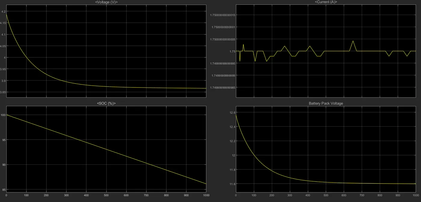
The simulation is run for 1000sec.
Conculsion:
Simulink model for 3S2P battery pack configuration is bulit with generic battery block. The simulation is run for 1000sec. The SOC of the battery has reduced to 86.1% from 100% and the maximum voltage of the battery pack has droped to 11.6V.