Project 1
1. Design a battery pack for a car roughly 150 Kw with 120 V. Use 3500 mAh 3.6V nominal NMC chemistry cell.
a. Design the battery pack configuration.
b. Draw the BMS topology for this battery pack.
Solution 1:
Since we have been provided the information that the particular battery pack is for a car, that means it is basically an electric vehicle and the primary energy consumption component will be for Traction purposes which will be provided by an Electrical Machine(Motor/Generator). therefore keeping this crucial information we can move forward with the design of the Battery pack knowing the application case.Also the Specifications of the Battery Cells are important for determing the final pack configuration. The Specification for the cell we have available to design the pack is:
| Nominal Capacity (Ah) | 3.5 |
| Nominal Volatge (V) | 3.6 |
Number of Cells in Series
For the battery pack design we need the Total Voltage requirement which should be based on certain motor voltage criteria, these are:
- Motor Recommended Voltage Rating
- Motor Maximum Voltage Rating
- Motor Minimum Voltage Rating
we have the recommended Voltage rating provided to use for the final appliation which is 150V.
Final Application requirements:
| Rated Motor Voltage (V) | 120 |
| Continuous Running Power (W) |
150000 |
this will help us determine the Number of Cells in Series in the Battery Pack for meeting the final application requirement. This can be easily found out using the simple formula:
1. Design a battery pack for a car roughly 150 Kw with 120 V. Use 3500 mAh 3.6V nominal NMC chemistry cell.
a. Design the battery pack configuration.
b. Draw the BMS topology for this battery pack.
Solution 1:
Since we have been provided the information that the particular battery pack is for a car, that means it is basically an electric vehicle and the primary energy consumption component will be for Traction purposes which will be provided by an Electrical Machine(Motor/Generator). therefore keeping this crucial information we can move forward with the design of the Battery pack knowing the application case.
Also the Specifications of the Battery Cells are important for determing the final pack configuration. The Specification for the cell we have available to design the pack is:
| Nominal Capacity (Ah) | 3.5 |
| Nominal Volatge (V) | 3.6 |
Number of Cells in Series
For the battery pack design we need the Total Voltage requirement which should be based on certain motor voltage criteria, these are:
- Motor Recommended Voltage Rating
- Motor Maximum Voltage Rating
- Motor Minimum Voltage Rating
we have the recommended Voltage rating provided to use for the final appliation which is 150V.
Final Application requirements:
| Rated Motor Voltage (V) | 120 |
| Continuous Running Power (W) |
150000 |
this will help us determine the Number of Cells in Series in the Battery Pack for meeting the final application requirement. This can be easily found out using the simple formula:
So we will have to round off the Number of cells in Series since only integer number of cells can be used in actual implementation.
usually the design criteria is that
for a motor having Rated Volatge of 120V the Maximum Voltage is easily around 200V. So let us assume the Maximum Battery Voltage to be 180V For the Maximum Battery Voltage Since we know that Li-ion batteries are having a Charge an Discharge curve which depends on whether the current is being taken out or being pumped in and according to the State of charge at any instant the voltage across ,or the voltage provided by the cell is different . Often termed as SoC Vs OCV graphs. so this means that the cell actually has a range of available voltage rather than a fixed constant voltage. And the upper limit of this is the Maximum voltage.Usually the Cells with a nominal voltage of 3.6V have a Maximum voltage(corresponding to 100% SoC) of around 4.2V
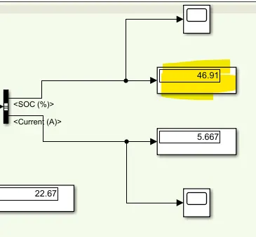
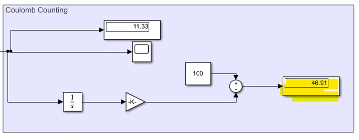
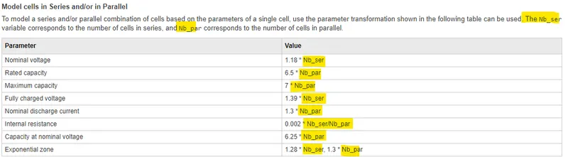
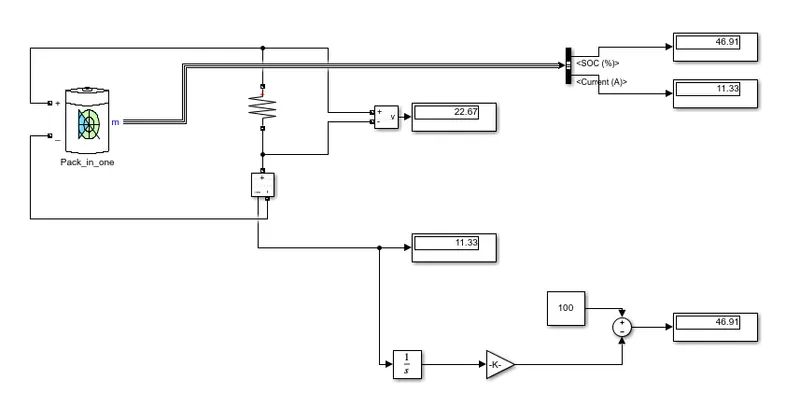
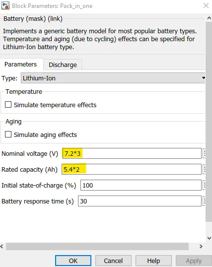
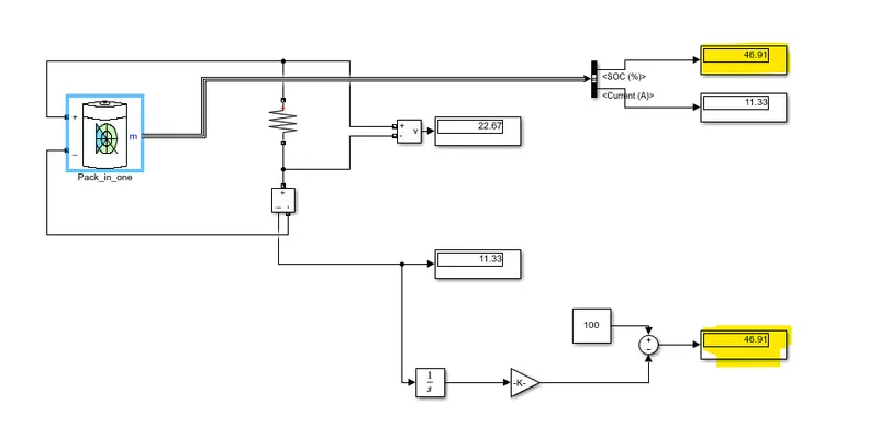
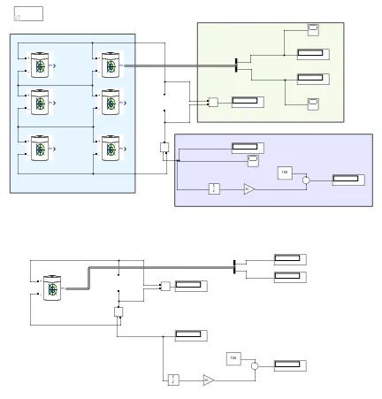
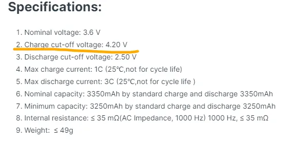
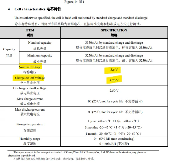
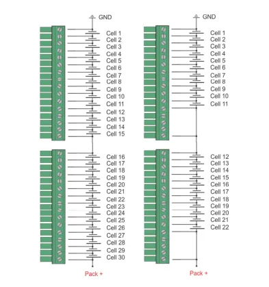
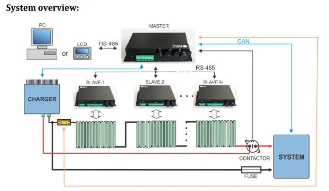
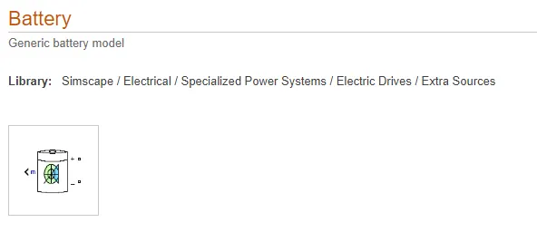
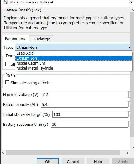
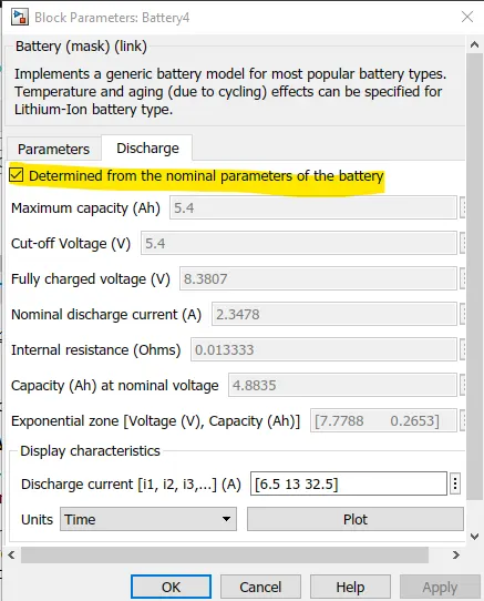
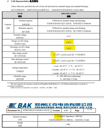
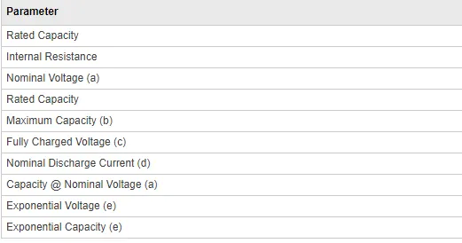
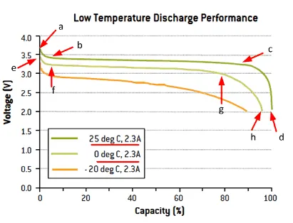
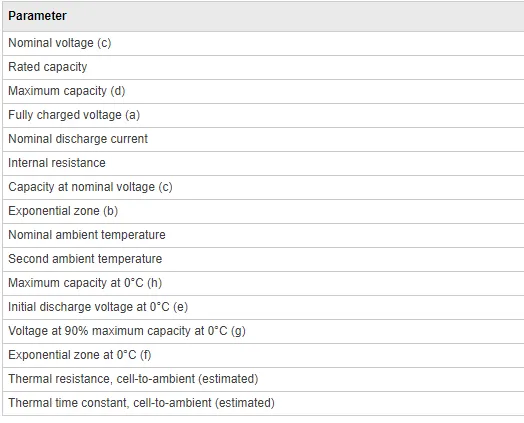
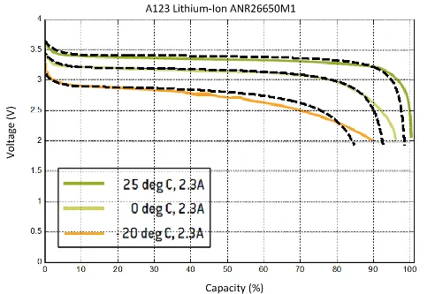
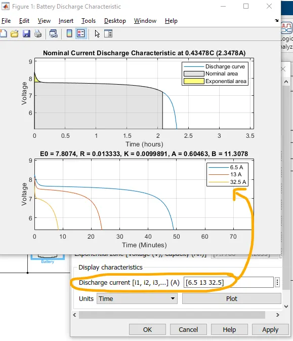
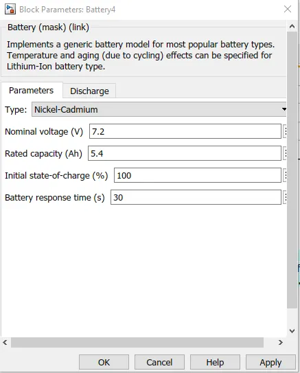
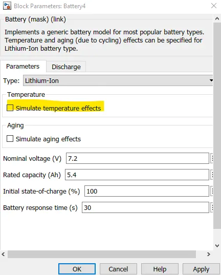
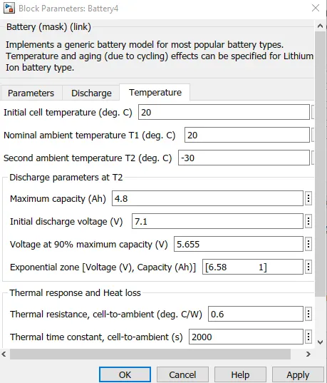
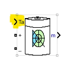
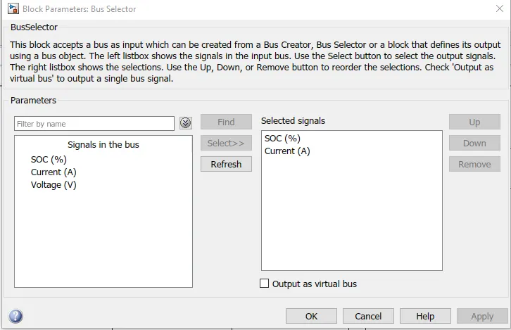
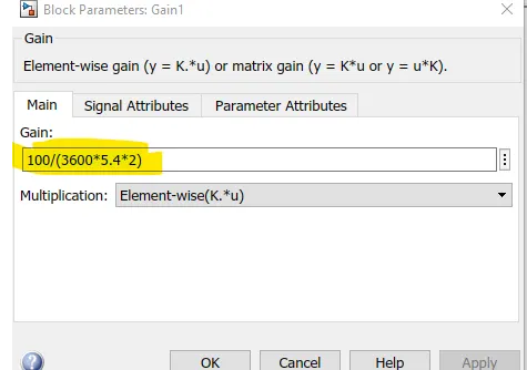
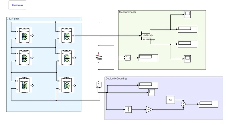
Fig: Typical Discharge curve for Li NMC cells, Illustration for the range of voltages Let us consider an example for this, Fig: an example of a Li-Ion NMC cell with Nominal voltage of 3.6V,same as our case and Capacity of 3350mAh(very close to our case of 3500mAh) we can see that the above Cell is the Same chemistry and same nominal voltage of 3.6 V. The Nominal capacity(3350mAh) is also very close to the theoretic cell provided to us(3500mAh ). In the same cell specification we can see the Maximum voltage for the particular cell . Maximum Voltage for a cell is also called Charge Cut-Off Voltage - this is because when the cell reaches this voltage during charging the charging is stopped or cut-off else the cell might overcharge and also can pose safety hazards beyond this point. Fig: We can see the Charge Cut off voltage or the Maximum Cell voltage is 4.2V Fig: From the Datasheet of the Cell above we can use the same Maximum Voltage limit for our cell,i.e. 4.2V So let us consider Rounding off to the Upper limit So Number of cells in Series = Round-Up(33.333) = 34 Checking for the design criteria thumb rules: in case of rounding down we will have : Number of cells in Series = Round-Down(33.333) = 33 Checking for the design criteria thumb rules: So we see both condition satisfy the rules but usually More Voltage is better. As other drops also exist,etc. So will chose the upper limit with more voltage i.e. 34 cells So we can conclude that the Number of cells in Series will be 34. Number of cells in Parallel For this we need to consider the Motor Continuous Current Requirement this can be found out easily using power rating given: Since we have been provided the Continous Power requirement of 150 kW Number of Cells in Parallel in the Battery Pack for meeting the final application requirement. This can be easily found out using the simple formula: So we will have to round off the Number of cells in Parallel since only integer number of cells can be used in actual implementation. Rounding off Let us consider both cases of Rounding Up and Rounding Down it is always better to discharge the cells at nearest & lower 1C rate. According to this, both are near 1C but still one is smaller and as we can see the C-rate is lower in the case of Rounding up we will chose that. So we can conclude that the Number of cells in Paralle will be 357. So the configuration for the Battery Pack will be :34S 357P a. Design the battery pack configuration. So the solution is :34S 357P b. Draw the BMS topology for this battery pack. We have mainly 4 BMS topologies that we can use for different application which are: Choosing a topology choice of the topology depends on the application and therfore the maximum amount of Voltage(number of cells in Series) required for the application. Why Voltage? this is because the AFE(analog front end) IC available in the Market at prresent can only accomodate upto a maximum of 18 cells. Taking the maximum voltage for Li-Ion cells of 4.2V even at maximum voltage for each cell we will get only a maximum of Fig: Illustration how mutliple Slave units are required for series cell connection(2 different pack examples) Left:needs 30 cells broken into 2 Slaves of 15 cells each and Right:needs 22 broken into 11 each for the EV application the Master & Slave Topology is the most widely used. This is because we do not need individual microcontrollers for each AFE as is the case in Modular Topology instaed it is more cheap and feasible to use Master & Slave since one microcontroller can comminicate with other AFEs. Fig: Master And Slave topology with 3 slaves The master can communicate with each slave directly or use a Daisy Chain Communication method. Fig: Slave selection for master using Binary addressing to avoid data collision on the Data Bus we have concluded that the Number of cells in the battery pack is 34. So as we know one AFE will accomodate maximum of 18 cells , so for 34 cells we need minimum of 2 AFE's.Each AFE will be forming a Slave susbsystem that will communicate with the main MCU. So the BMS topology chosen is : Master & Slave. With 2 Slaves. 2. Build a 3S2P battery pack configuration with generic battery block using Matlab/Simulink. Solution 2: The following configurtion can be easily implemented using Simulink. the main block that we will require are as follows: Battery: Fig: Battery block for a generic battery model the battey block is used to implement 4 different chemistry batteries which are: Fig: 4 different Types of chemistries we will be using" Li-ion cells with Nominal Voltage 7.2V and Nominal Capacity 5.4 Ah. Behavior of the Battery: we know that the battery usually has a typical charge and discharge curve for the description of it ecpected behavior across the SoC range, this can be : Fig: I have chosen the behavior to be detrmined by the Nominal parameters we provided if we hav the datsheet of the battery we can provide the parameters ourselves.Consider the data sheet of the NMC cell we saw in Quesion 1: Fig: Illustration of how the datsheet can be used to define parameters if we chose to do it on our own rather than using "determined from nomimal parameters checkbox " Typically some of the parameters are directly available in the datsheet other parameters we hve to extract from the "Typical Discharge Characteristics" usually prcovided in the cell Datasheet. Fig: Parameters we need to provide if not using "determined from nomimal parameters checkbox " Example of extracting the other info form the "Typical Discharge Char" Fig: Example of the A123 LFP ANR26650M1 cell datasheet in Typical Discharge Characteristics from selection of certain points we can obtain the model parameter values to provide in the "Discharge" menu of the cell. refering to the marked points and the parameter needed for the discharge curve we can map the paraneters needed in the Block Dialog box and the marked points in the provided datasheet Typical curve as: Fig: Mapped parameters to the Typical behavior curves in the datasheet for the cells. if we provide the paremeters using the points in the discharge curve. We can see that the curve developed from Simulink is very close to that of the acvtual experimentally recoded curve. Fig: Black dotted-Estimated from the values given, colored - actual datasheet curves we see the model perfomance is very close to the actual.The accuracy of the model depends on how precise the selected points from the data sheet discharge curves are. We can plot the discharge characteristics for different discharge current. We get two plot: one at nominal discharge rate, the other with other diacharge currents we provide: Fig: Nominal Discharge Current (above) and provided discharge current plots. Also it is worth mentioning that in Case of Li-Ion battery there is need for curves at 2 different temperature, ambient and another test temperature. This is to incluse the effect of cell operating temperature in the model of the cell. this is NOT present in other 3 Chemistry cells. this we can see as below. Fig: Notice how no temperature effect option is present in Ni-Cd type but is present in Li-Ion type if we check the box then we can also simulate the temperature effect happening during the operation of the cell. This will give us another section of the Temperature. Fig: temperatue section of the Li-Ion battery parameter box. the parameters we provided in the Parametre will correspond to the T1(Nomal Ambinet temperature) as we can see above. The Second temperature as said earlier will be corresponding to the curve derived experimanetally and provided in the datasheet. We will use values from this curve the same we did for the Ambient temperature and input them in the "Discharge Parameters at T2". We also need to provide the thermal resistance from cell to ambient and the thermal time constant. enabling this will ask us for the Ambient temperature from a new terminal Fig: Ambient Temperature input when Temperature effect is enabled Bus Selector: As mentioned the Output from the Battery will consist of many signals we will want only those which we are interested in: Fig:Selecting only SOC and Current for output from the 3 signals available Gain: As mentioned we need to multiply by the fig: The Battery Pack configuration can be implemented can be seen below: Fig: Imnplemented model. 3S2P pack, Measurements and Coulomb counted SOC calculation Cell And Pack paremeter: Choice of Resistance Since we know that any resistance can be chosen but in order to confirm that the model is working we want to select the value of resistance which will give us 1C-rate of discharge at 1 C-rate= current = Nominal capacty of the pack = 10.8A and voltage is same = 21.6V so resiatnce for Nominal 1C rate discharge = 21.6/10.8 = 2ohms So in order to confirm validity we will run for 0.5 hours with the above R and the total discharge should be around 50% and the remaining SoC should be around 50% Results: Fig: Soc mesaured at the end of 1800s Inference:we see that the SOC is near to 50% but not exactly 50% which is completely expected . this is beacuse the current will not remain constant flowing through the resistance. Because we chose th value of resistance at the nominal values but that is not the case we know as the Voltage has a curve an is not constant so the Voltage in the beginning at 100% soc is 4.2V and then changes as soc Changes with extraction of charge. therefore the voltage across R is not same (21.6V) and changing and hence current will also be changing meaning charge rate taken out is not exaxtly same all the time instants. Therefore a small variation is seen beacuse of that. has we taken a constant current load with 1 C-rate then the soc would have been exaxtly 50% at the end of the simulation. From the Coulomb counting: Fig: From coulomb counting we get the exact value as depicted by the SoC from the cell Inference: coulomb counting is implemented successfully. An important feature in the Battery block we can further read in the documentation for the battery block and find that instaed if making connections with other cells in series and parallel as we did we can directly implement it in the block itself. Fig: Using simple Pack formulas to make the battery block a whole battery pack block explaination: we can simply multiply the No of cells in series with the Nominal Voltage of the cell and the Number of cells in parallel with the Nominal capacity of the cell to get the same pack using one battery block. Note: we only need to do the first 2 multiplucation since we have chosen the "Detemine from thre Nomical parameter" option. If we had used datasheet we would have to multiply other parameters too (from third column in the above table) Implementing in our model & checking: Fig: Using One battery block instaed of making connections updating the parameters acc to number of cells in series and parallel. Fig: updated Voltage and Capacity Nominal Voltage of pack= Nominal Voltage of cells X Number of cells in Series = 7.2*3 Nominal Capacityof pack= Nominal Capacity of cells X Number of cells in parallel = 5.4*2 Results: Fig: Result with the Pack implemented as one battery block Inference:we can use oly one battery block and implment the pack instead of making connections as we did before and get the same results. Both of the models are included in the same .slx file for eae of comparison Fig: Model above: with cells, Below: one block as a pack. will get same result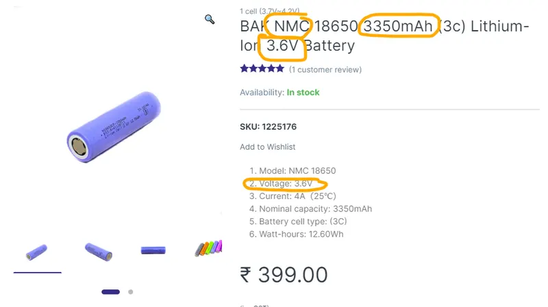
Thumbe rule while rounding off
Actual case
Actual case satisfied or not
Thumbe rule while rounding off
Actual case
Actual case satisfied or not
Case 1: Rounding up
Case 2: Rounding Down
Number of cells = 358
Number of cells = 357


Nominal Capacity of cell
5.4Ah
Nominal Voltage of cell
7.2V
Nominal Capacity of pack
=Number of cells in Parallel X Nominal capacity of one cell
=2X5.4=10.8Ah
Nominal Voltage of pack
=Number of cells in Series X Nominal voltage of one cell
=3X7.2 = 21.6V