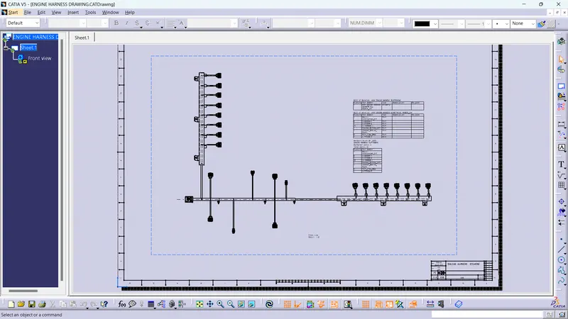
Project 1
AIM
- To Route the Wiring harness on Given Engine and Prepare flatten view drawing in CATIA V5. Application of all Packaging rules, Industry best practices studied in this course shall be demonstrated in design.
- Available connector 3D data can be used, or we can download the connectors from www.te.com
- Preparing all necessary reports like clearance, Clipping/Clamping selection, Harness fixing requirements, Harness continuity, Assumptions if any along with CATIA 3D data.
DEFINING CONNECTORS AND SUPPORT PART ELECTRICALLY
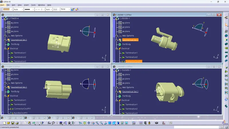
- All the connectors are defined electrically
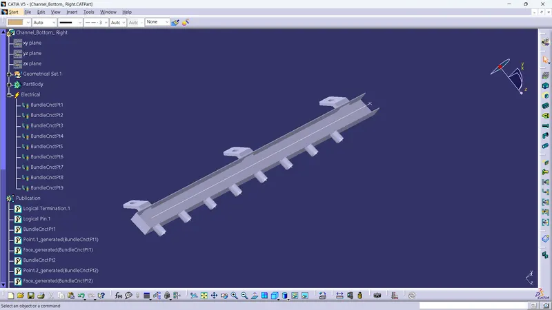
- Guiding channel is electrically defined
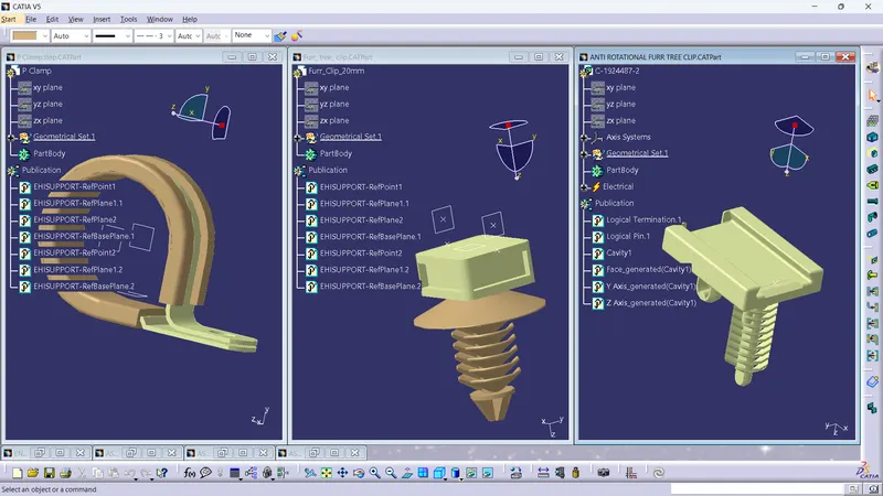
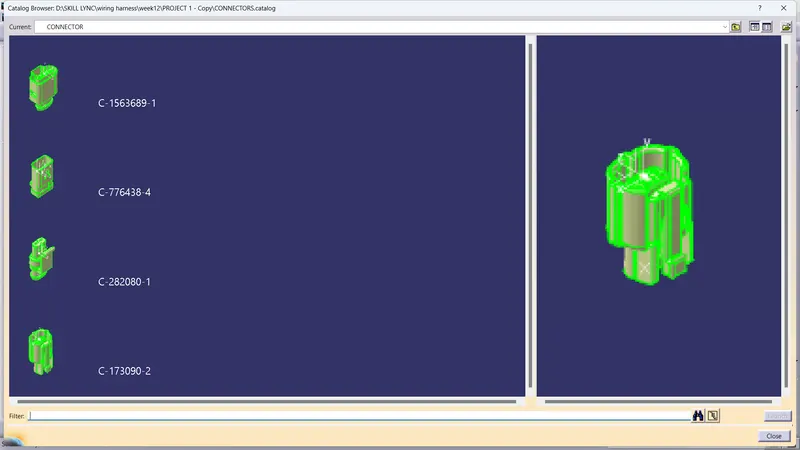
CATALOG FOR CONNECTORS
ENGINE HARNESS CONTEXT
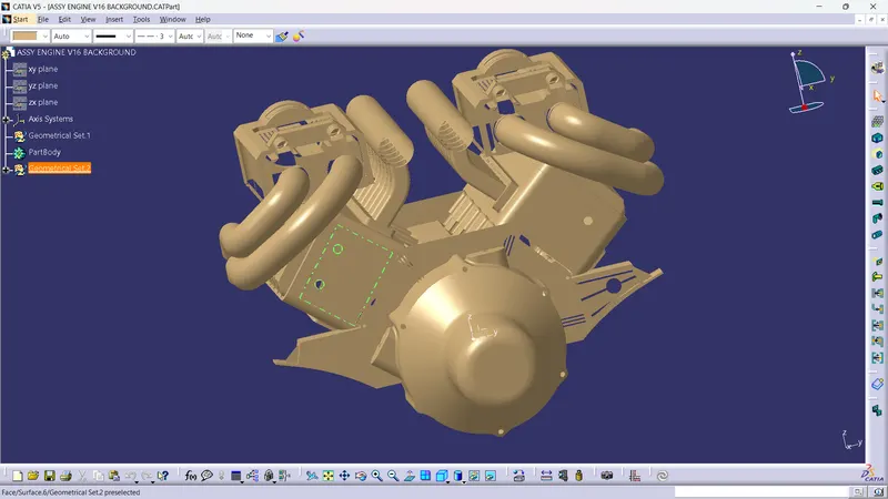
- The engine is given for the harness
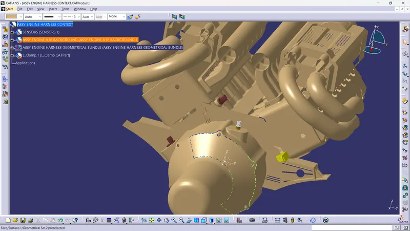
- The sensors are place in the right location
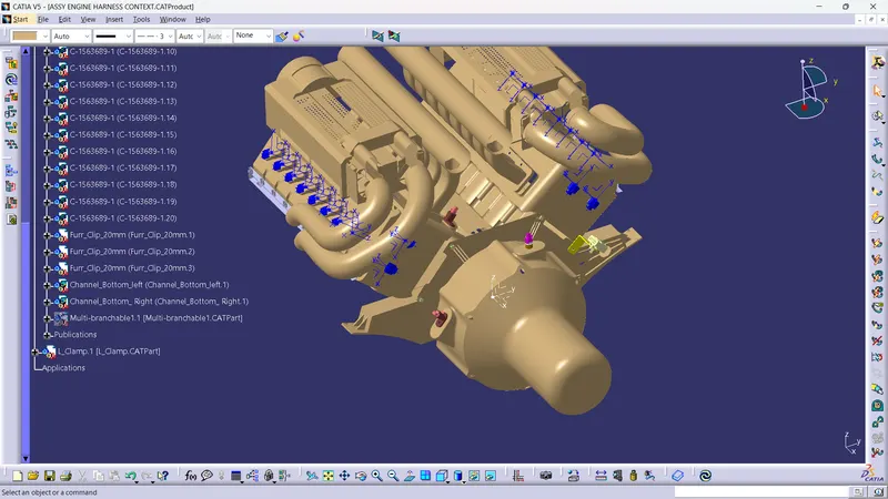
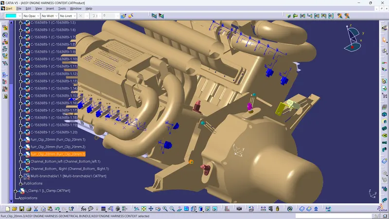
- The connectors are placed in the correct position and the supporting parts (fir tree clip, guiding channel)also
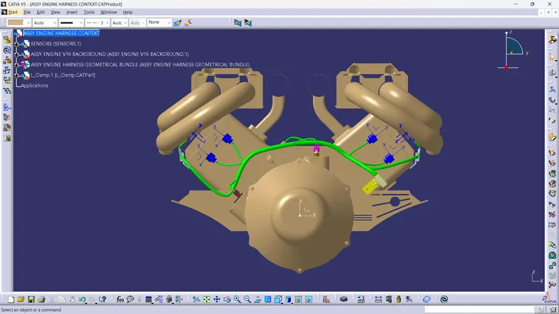
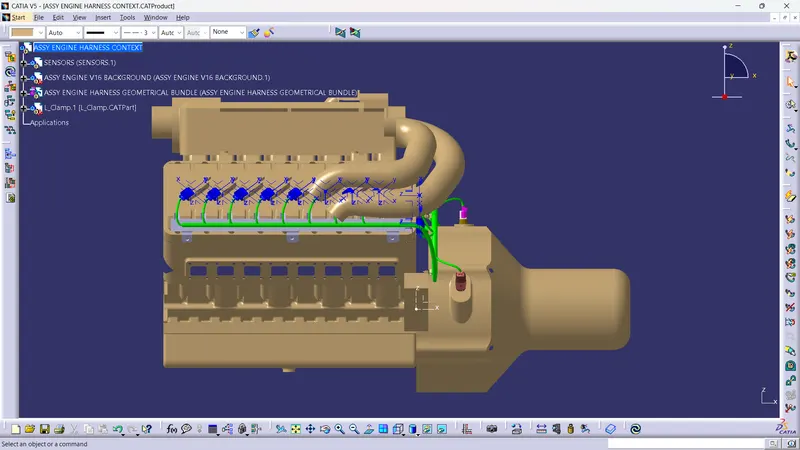
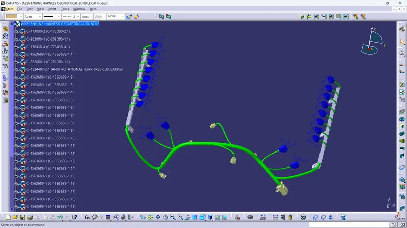
- Harness bundle is created in the engine
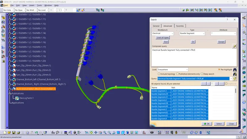
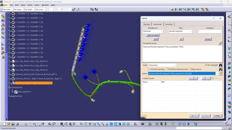
Harness continuity
FLATTENING THE HARNESS BUNDLE
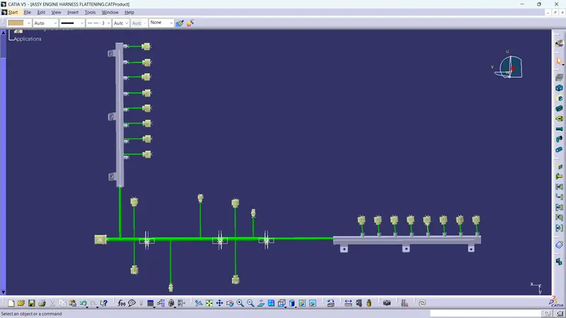
DRAWING