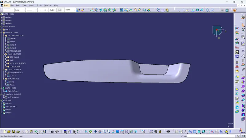
Week 8 - Challenge 2 - Switch Bezel Design
SWITCH BEZEL
AIM:
Create the Switch Bezel Plastic component through the given Class-A surface. To begin with, the tooling axis for the given Class-A Surface should be created meeting the requirements of the draft angle and at the end perform the Draft analysis on the model.
CREATING THE TOOLING AXIS
- First neet to find the direction the component will get eject without any damage
- Then we need to create the tooling axis for it
- The tooling axis also used in create class c and draft analysis tool
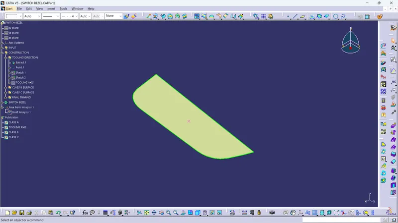
- For creating the tool axis we need to extract the base and create a point in it
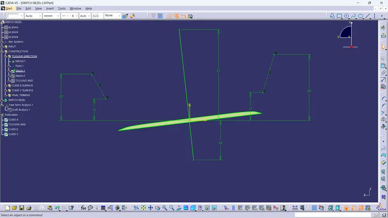
- Then intersection is used to create the wall line then the bisecting line was created its just a dummy line
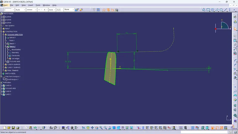
- Another line is created by using intersection and there is no other side wall so a line is create in 3 degree from the point
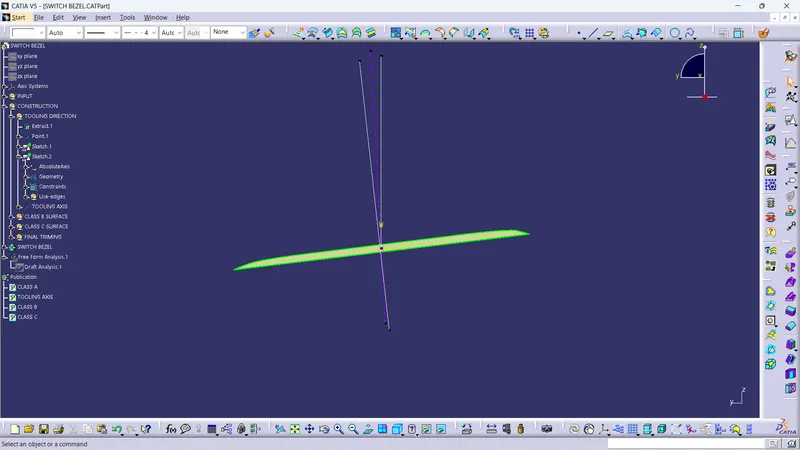
- Tooling axis is created bisecting those lines
CLASS B SURFACE
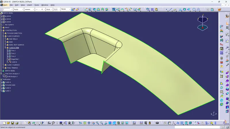
- For CLASS B need to extract the base ,side walls, the bezel rest surface
- Then untrim them and extrapolate them now we have to offset them to 2.5mm
- Now we can trim them into single profile
CLASS C SURFACE
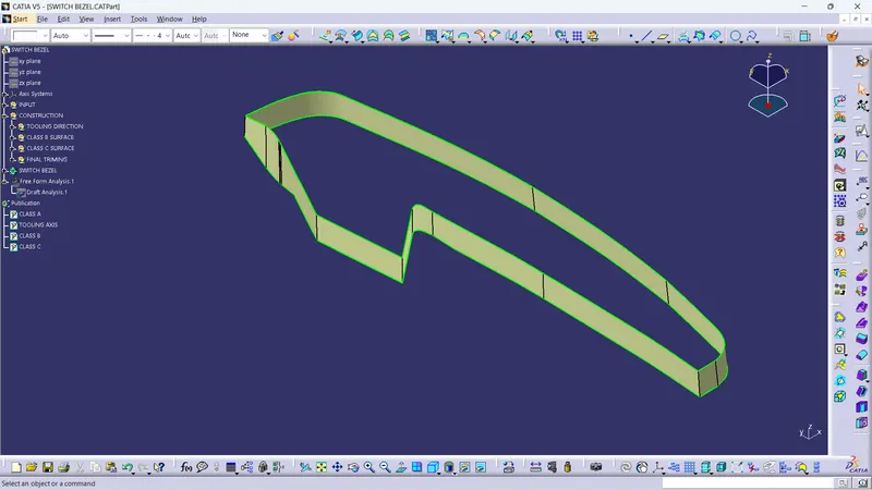
- For this class c creation we need tooling axis first we need to extact the boundrys of the class a
- Then the sweep command is used to create the class c the angle 3 degree is given
FINAL TRIM
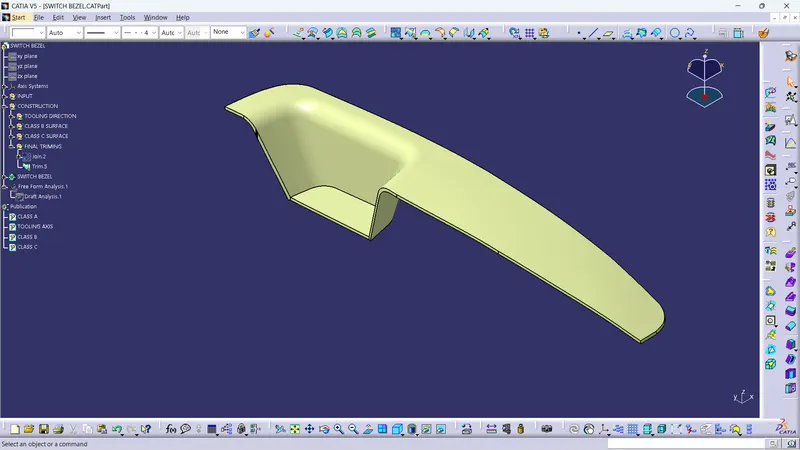
- The CLASS A and CLASS C was joined by the join command
- Then tha jion and CLASS B was got trimed
CLOSE SURFACE
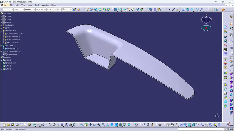
- The solid body is created by using the close face command
DRAFT ANALYSIS
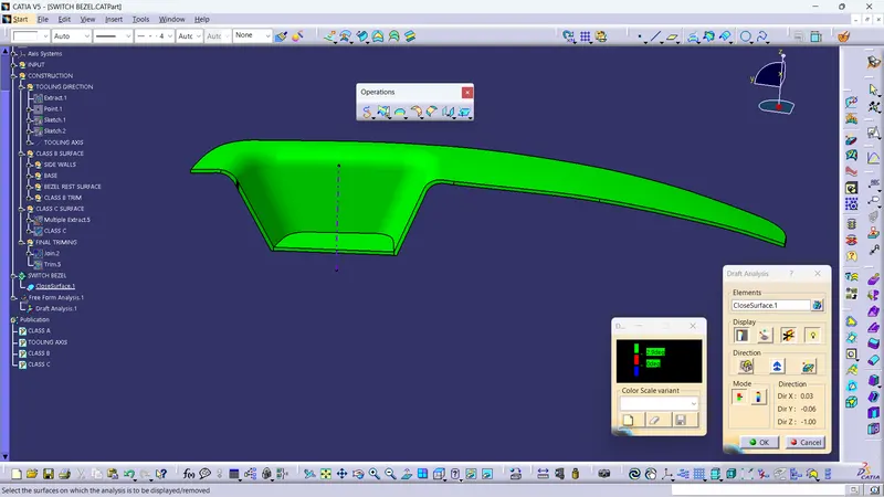
- Draft analysis is done by the tooling axis to the solid body and 2.9 degree is given
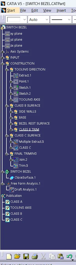
TREE STRUCTURE
ISO VIEW
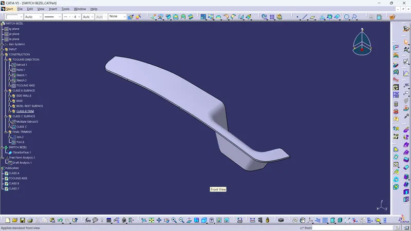
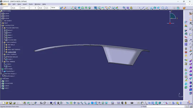
FRONT VIEW
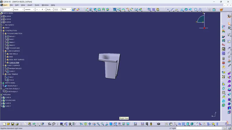
SIDE VIEW
TOP VIEW