Project 1
Objective
- To route the wiring harness on given engine
- To prepare flatten view in CATIA V5
Introduction
Wiring harness forms the backbone of the electrical architecture in any vehicle electrical system design. Wire Harness is the interconnecting wiring in the vehicle for the transmitting electrical power and signals in the electrical system. The increase in the electrical and electronic content in the automobiles has resulted in the wire harness design becoming more and more complex. From the simple function of electrical power distribution and transmitting signals, it has become a networking of multiple controllers with a vast range of sensors, actuators and their interfaces. Many CAD tools and design software have evolved to virtually develop the harness.
An Engine Wiring Harness is an organized set of wires, cables, connectors and terminals that control a vehicle’s electrical system. Engine wire harnesses relay electrical power and control information to outlying components such as:
- Alternators
- Audio Systems
- Batteries
- Blower Motors
- Computers
- Fuel Injectors
- Fuses
- Windshield Wipers
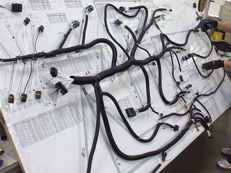
Image below shows typical wiring harness system designed for vehicle.
Engine harness design criteria and packaging rules
- Wiring harness should be routed in such a way that it is easy to assemble on vehicle. Wiring harness topology plays important role to meet this criteria
- Wiring harness should be routed in such a way that it is easy to access in case of service or failure analysis
- Wiring harness routing shall provide ease in manufacturing, accessibility, easy removal and easy maintenance of attached equipments and wiring harness
- Routing through small structural holes and openings shall be avoided to minimize chaffing and handling of the wiring harness during installation
- Provide additional slack to the harness according to the surrounding and harness bending requirements.
- Ensure that worst case envelope dimensions are considered for dynamic assemblies to meet the desired clearance requirements with wiring harness bundles.
- Avoid routing over the bolts, near the bolted joints or screwed joints. It may damage harness or may puncture the harness
- Avoid the harness routing near the sharp edges or over the sharp edges like thin sheet metal brackets, panel joints.
- Ensure that harness is routed at least 100 mm away from ABC pedals, clutch lever and cables, engine timing belt or any other dynamic components.
- Enough clamps shall be provided to ensure the positive clearance with surrounding and safety of wiring harness. Distance between two clamps on a straight branch should be maximum 200 mm.
- If harness is routed between dynamic and stationary assemblies, then ensure that fixed positive clamping is provided immediately at the both end of assemblies. This is required to avoid harness damage in rocking conditions.
- Harness should be kept away from engine lifting hooks
- Use of rubber grommets is recommended if harness is passing through sheet metal panels. Rubber grommets must be used if harness is subjected to vibrations or mechanical fatigue loads/movements. Rubber grommets must eb used if harness is passing through wet zone of the vehicle.
- Telescopic grommets are recommended to use for the harness passing through closures
- Ensure that harness branching is in line with following requirements
- Branch length should be minimum 50 mm.
- Minimum distance between clip and nearest branching point should be 25 mm
- Minimum distance between two breakouts should be 50 mm
- Limit the number of branches from single branching point to 4
- Ensure that harness protection is provided according to surrounding temperature, manufacturability and expected reliability
Engine harness design procedure
1. Define all connectors, clippings and clamping. Image below shows the connectors, clips and clamps used in the harness routing
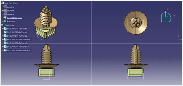
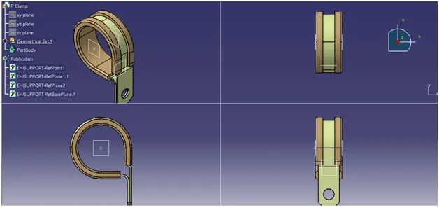
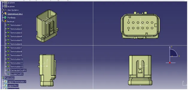
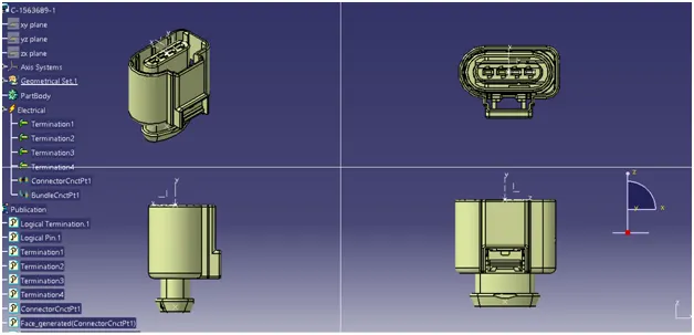
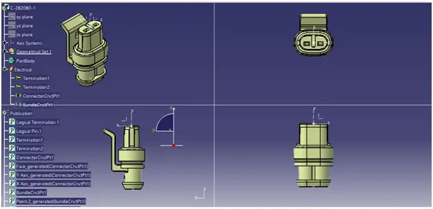
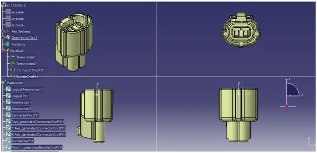
2. Check for all connector positions, clipping and clamping positions in the given engine data. All the connector positions are highlighted in blue color as shown in image below
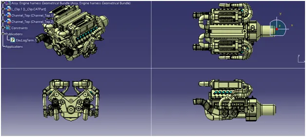
3. Place the connectors at the required positions using manipulation tools as we are performing conceptual routing.
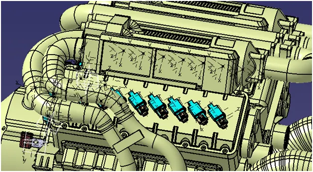
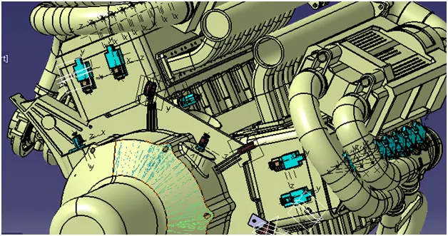
4. Carryout routing process following all routing and packaging rules as explained before.
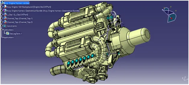
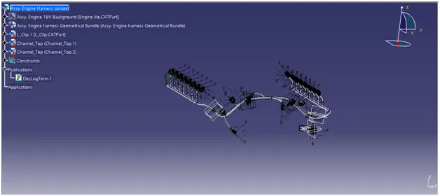
5. Bundle continuity check analysis is performed and the result is shown in the image below
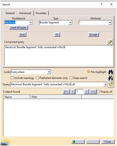
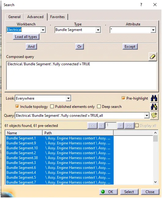
From the above result it is clear that there exists no discontinuity in the wire harness
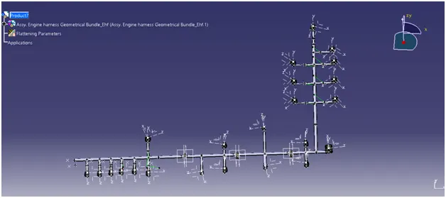
6. Wire harness flattening is carried out in wire harness flattening work bench as shown in image below
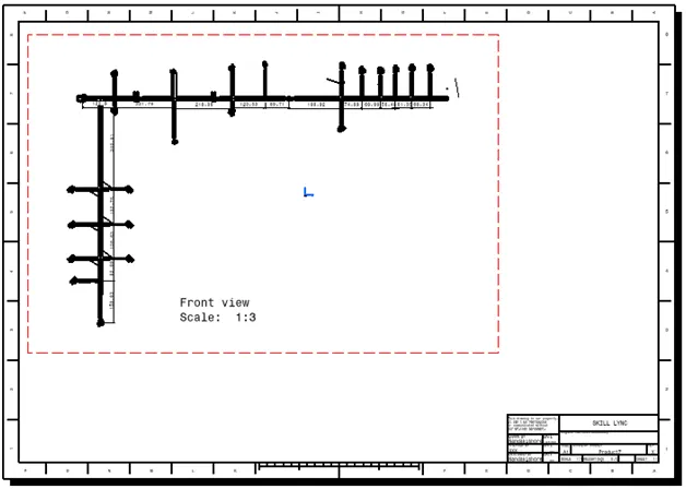
7. Drafting
Conclusion
- Conceptual Routing is completed for the given engine cad data following all predefined design and packaging rules
- Continuity check is performed and the results obtained are satisfactory
- Wiring harness flattening is carried out and images are uploaded
- Wiring harness flattened drawing view is created