Project 1
OBJECTIVE
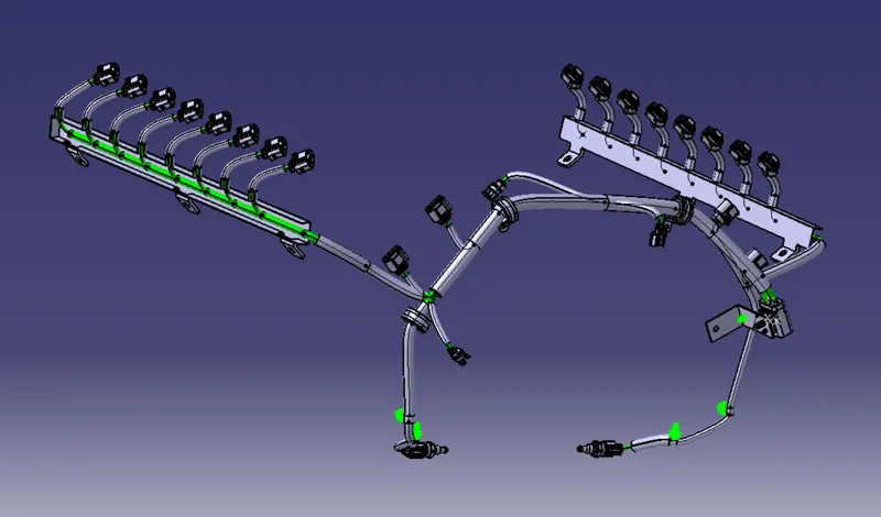
Route the Wiring harness on Given Engine and Prepare flatten view drawing in CATIA V5. Application of all Packaging rules, Industry best practices studied in this course shall be demonstrated in design. Apply Protection coverings as required.
INTRODUCTION
In this Project i have done wiring Harness of a V16 engine in which 8 cylinders are placed on left side and 8 cylinders are placed on right side and 4 cam shaft sensor are placed.
Wiring Harness
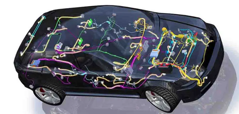
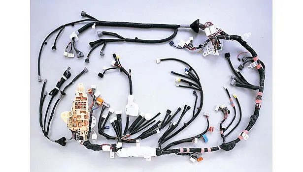
Automotive wiring harness is defined as an assembly of wires, terminals, and connectors that run throughout the vehicle to transmit information and electric power. Automotive wire harness is designed according to electrical & dimensional requirement of automobiles and is integrated to connect different parts of vehicle such as body, engine, dashboard, chassis, and others. Automotive wiring harness enables transmission of control signals and electrical power to electronic & electrical devices in an automotive to ensure basic functionality & enhanced safety.
Harnesses are designed as per the electrical and geometrical requirements of automobiles, and are embedded in the body, engine, and chassis of vehicles. Body wiring harnesses are embedded into dashboards, door locks, power windows, and interior electrical components. Engine wiring harnesses embed into speed sensors, lock breaking systems, cruise control systems, and fuel injection systems. Chassis wiring comprise of the front, rear and main harnesses.
CONNECTOR
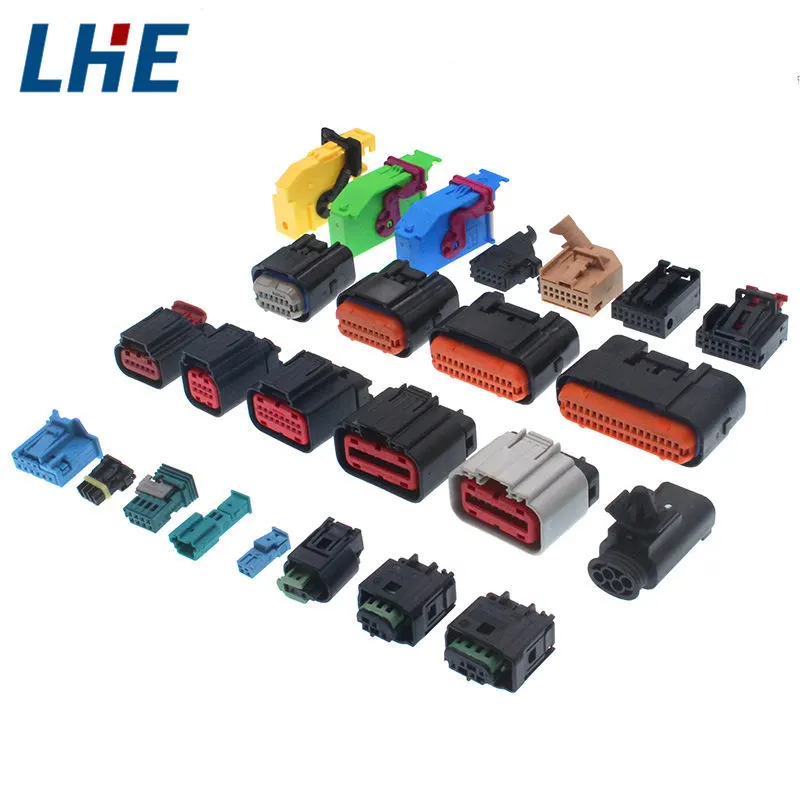
An electric connector is an electro mechanical device used to create electrical termination and create electric circuit. Electric connector consist of Housing, Terminal, wedge locks, seals, cavity, mounting cams, etc. These are responsible to make connection between harness and component.
Following Parameters are required to define for any connector:-
1- Geometric Parameter - Points and Co- ordinate system (Axis)
2- Connector Connection Points - This points is used for the connection of one connector with another connector
3- Harness Bundle Entry Point - This Point define where bundle segment point will end when routed to the electrical connector
4- Cavity Connection Point (Optional) - This point is used to define the connection of a connector with mounting clips. This only applies when the connector have the mounting feature for mounting clips.
ROUTING PROCESS:-
STEP 1- Download the Engine Cad data & the required Connectors
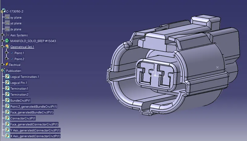
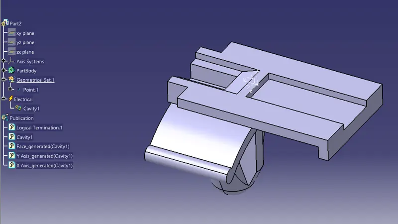
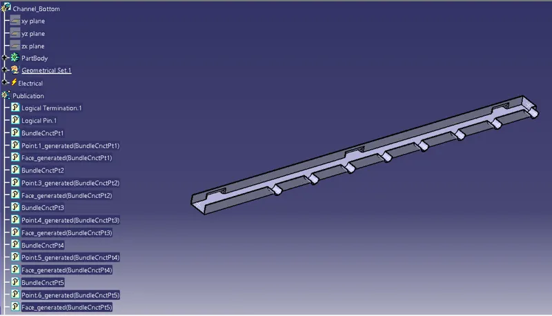
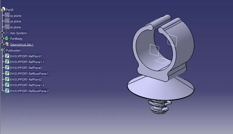
STEP 2- Define connectors & Connector clip as Electrical Connector using Electrical Part design Workbench. Define all the necessary properties to Connectors & Clip.
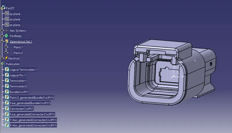
- Create required Geometrical parameters. Create 2 points on the middle of both ends of the part and Create a axis system on the mating face. Put Y axis to the other Mating part and X axis towards the Locking system
- Define Part as a Connector
- Define " Bundle Connection Point "
- Define connector connection point.
- Define cavity connection point. ( If necessesary )
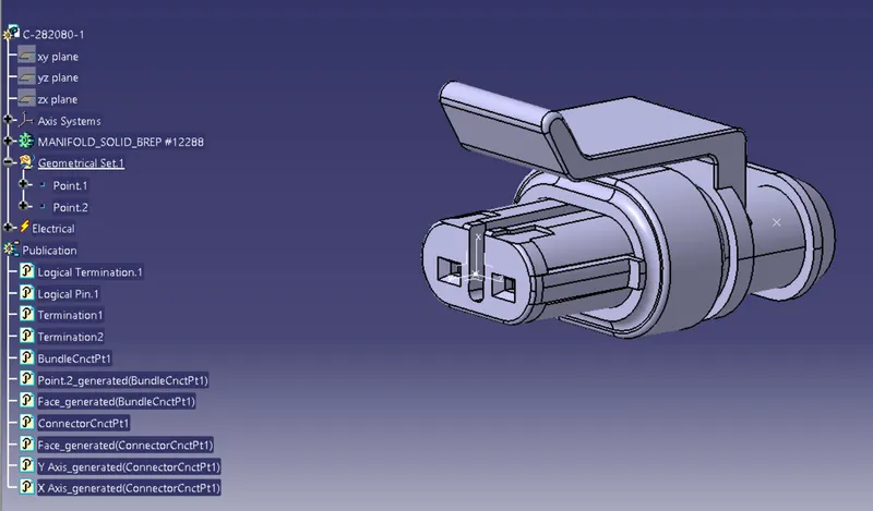
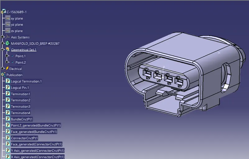
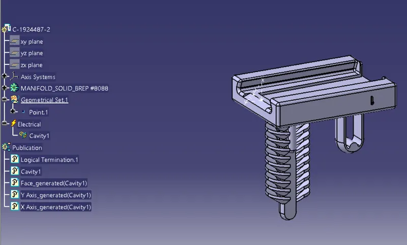
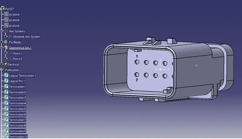
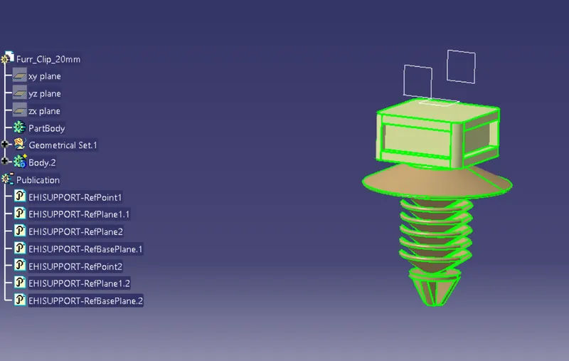
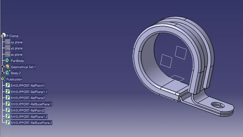
STEP 3- Create a Context assembly Where we assemble all the connectors and clamps clips with the Engine CAD and perform routing operation
STEP 4- Add connector for the Cam sensors & injector, neutral sensor, temperature sensor, Oil pressure sensor and coolent Temp. sensor also Position all the clips, clamps and guiding channel for the Bundle routing.
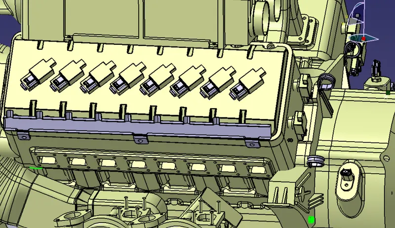
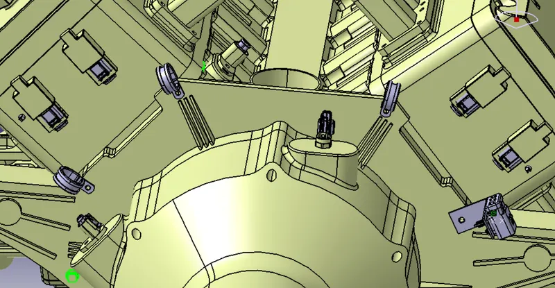
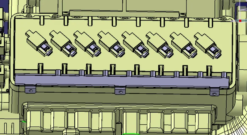
STEP 5- Start routing from the Interconnection Connector and go along with the P clamps and Fur clips. Add Sub Branch for the cam shaft connectors and guiding channel.
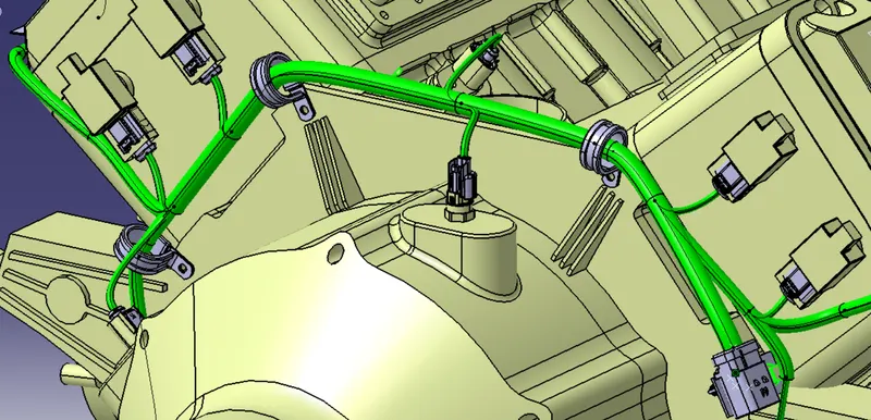
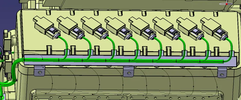
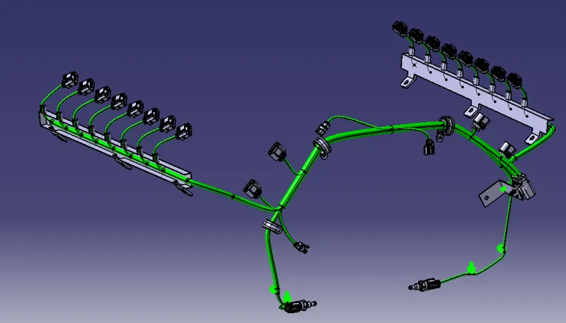
STEP 6- Add protective covering to the bundle according to the diameter of the bundle.
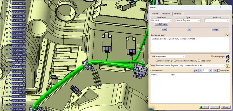
STEP 7- Check For the bundle continuity. Here we have chosen FALSE option so if there is any discontinity it will be shown in the below description. Here nothing is shown in the description so there is no discontinuity.
STEP-8- For the Flattening operation,
- Create a new Product file
- Go to Electrical Harness Fattening Workbench
- Extract the Geometrical Bundle into the new product file
- Use Flatten Command to flatten the bundle
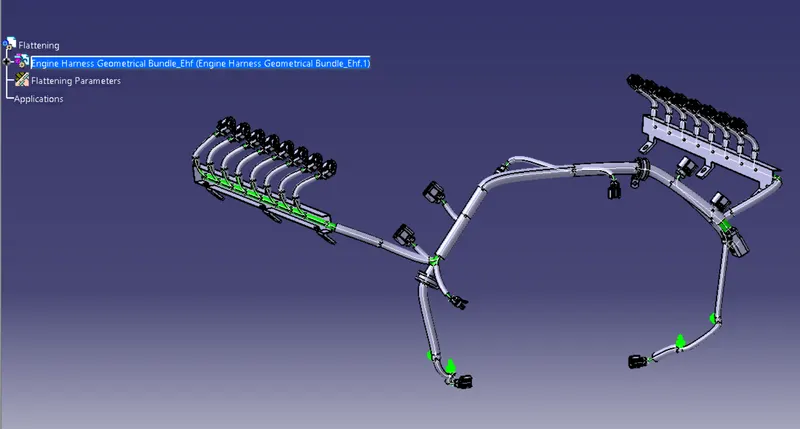
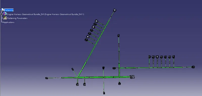
STEP-9 - Create a drawing File and Project the view of the Flattening Bundle
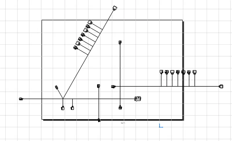
ENGINE WIRING HARNESS
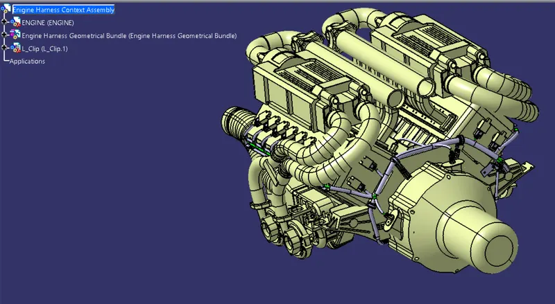
CONCLUSION
Here I have completed Wiring Harness of the Engine with all the routing parameter, Packaging rule and Industries Practices