Project 1
Project 01(WIRING HARNESS FOR ENGINE)
AIM:-
- To route the wiring harness for the given engine.
- Application of all Packaging rules, Industry best practices studied in this course shall be demonstrated in design.
- Apply Protection coverings as required.
INTRODUCTION:-
WIRING HARNESS OR CABLE HARNESS:-
A cable harness, also known as a wire harness, wiring harness, cable assembly, wiring assembly, or wiring loom, is an assembly of electrical cables or wires which transmit signals or electrical power. The cables are bound together by a durable material such as rubber, vinyl, electrical tape, conduit, a weave of extruded string, or a combination thereof.
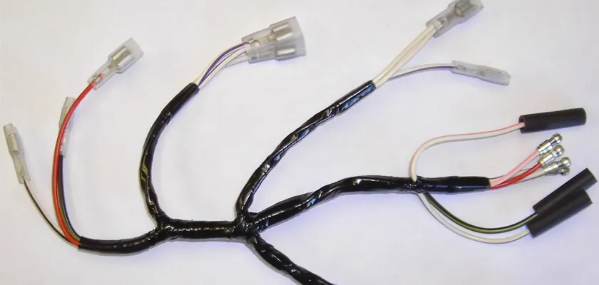
Cable harnesses are usually designed according to geometric and electrical requirements. A diagram is then provided (either on paper or on a monitor) for the assembly preparation and assembly.
The wires are first cut to the desired length, usually using a special wire-cutting machine. The wires may also be printed on by a special machine during the cutting process or on a separate machine. After this, the ends of the wires are stripped to expose the metal (or core) of the wires, which are fitted with any required terminals or connector housings. The cables are assembled and clamped together on a special workbench, or onto a pinboard (assembly board), according to design specification, to form the cable harness. After fitting any protective sleeves, conduit, or extruded yarn, the harness is either fitted directly in the vehicle or shipped.
- Wires:- Wiring harness consists of various wires bundled together, with each individual wire responsible for carrying electric signals and energy used ins tarting the engine, lights, meters, navigation system, Power windows and doors, and other devices in the vehicle. Wires are Cu conductors insulated with PVC insulation. Initiative in the industry to use the Al wire to get the benefits of weight and cost reduction.
- Connector:- An electrical connector, is an electro-mechanical device used to join Electrical termination and create an electric circuit. Electrical connectors consist of Housing, Terminal, Wedge Locks, Seals, Cavity, Mounting Cam etc., Connectors are plastic moulded housing with locking and retention features.
- Terminals:- Terminals are defined as “A device designed to terminate a conductor that is to be affixed to a post, stud, chassis, another tongue, etc., to establish an electrical connection.” Terminals are metal (brass) conductor with plating (tin, silver, gold) constructed in specific shape to secure the joint from environmental conditions and with minimum electrical resistance.
- Protection device:-
- Corrugated flexible tubes also known as Cot Tubes / Convoluted Conduits have a wide range of application in automotive industries.
- Corrugated tubes are made from plastic material and they are flexible.
- Theses tubes are used to protect the harness from thermal and physical damage, sometimes to improve harness appearance.
- Protection covering are flexible, temperature, wear and tear resistant moulded plastic/polymer parts.
- Sealing Grommets are used mainly for three purposes. Sealing, Protection and to absorb vibration/shock.
- Protection Grommets are rubber moulded components used in wiring harness for protections.
- Insulations are adhesive/non-adhesive tapes and sleeves. They are made from PVC or cotton/polymer material. Cotton tape in high temperature area (engine).
- Clips and clamps:- Wide variety of clips and clamps are available to mount the wiring harness.
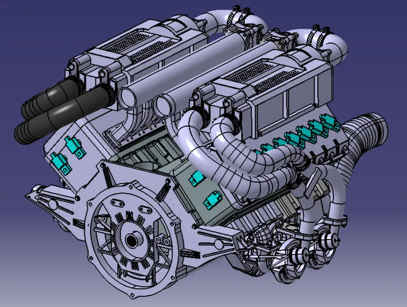
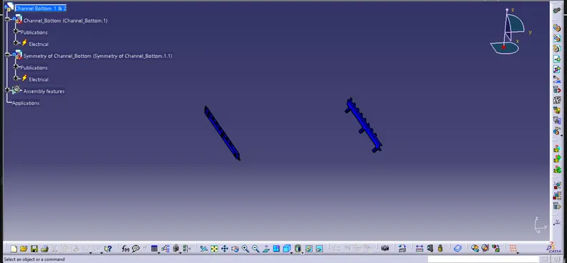
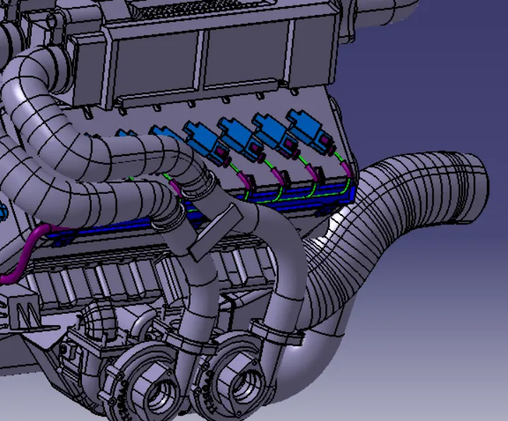
- Guiding channels:-The engine has 8 fuel injectors on the left side and 8 fuel injectors on the right side of the engine. All these fuel injector sensors are located very close to each other. So, the best way to route the wires around them is by using a plastic guiding channel as they will help us organize all the wires very precisely and will reduce complex wiring harness routing. To mount the plastic guiding channels we would need some mounting provisions. The engine design team can be consulted and asked to provide mounting threaded holes or threaded bosses.
There will be two different plastic guiding channels for this engine. One for the left and theother for the right side of the engine. It has to bemade sure that proper clearance (at least 50mm) is provided between the plastic channel andthe exhaust pipes. The total thickness of thethese channels is 25 mm.
The plastic guiding channel will be a two-piece molded plastic that will protect the wiring harness from surrounding high temperatures, wear and tear while providing nice aesthetics to the engine.
GIVEN ENGINE:-
DESIGN CRITERIA AND PACKAGING ASSUMPTIONS:-
- Wiring harness routing shall provide ease in manufacturing, accessibility, easy removal, and easy maintenance of attached equipment and wiring harness.
- Routing through small structural holes and openings shall be avoided, minimize chaffing and handling of the wiring harness during installation.
- Avoid the harness routing and clipping in the Blind zone of the Operator during harness assembly or in service.
- Routing shall offer protection against possible damage through common misuses such as being handhold and temporary support for test equipment.
- Provide additional slack to the harness according to the surroundings and harness bending requirements.
- Ensure the routing meets the clearance requirements with different surrounding parts.
- Avoid routing over the bolts, near to the bolted joints. It may damage the harness or puncture the harness. Keep harness away from panel mounting screws.
- Avoid harness routing near sharp edges, if not possible provide protection to the harness.
- The maximum distance between two clips on a straight branch is 200mm.
- Provide Clips and clamps if the harness is going to bend at multiple locations.
- The use of too many sheet-metal brackets should be avoided.
- The branch length should be more than 50 mm.
- Min distance between clip and branching point to be 25 mm.
- Min distance between two branch breakouts should be 50 mm.
HARNESS ROUTING:-
CONTEXT:-
Creating Context Assembly:-
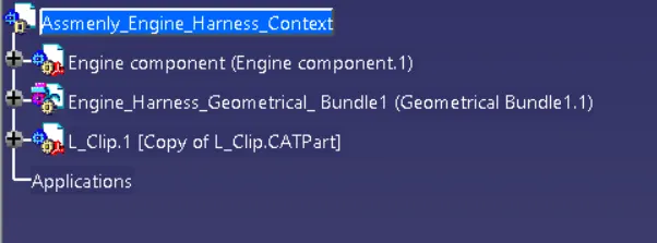
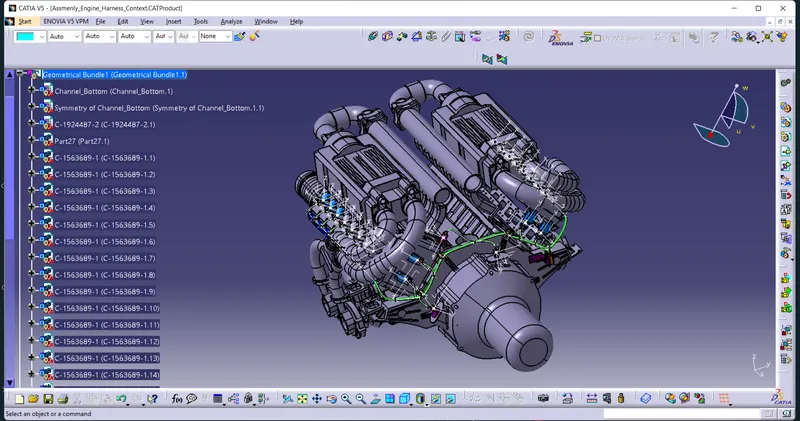
A context assembly has to be created which will serve as the main assembly for engine harness. The context assembly will contain the 3D-CAD data for the engine and the engine harness geometrical bundle. If any sheet metal brackets are required then they are added in this "ASSY ENGINE HARNESS CONTEXT".
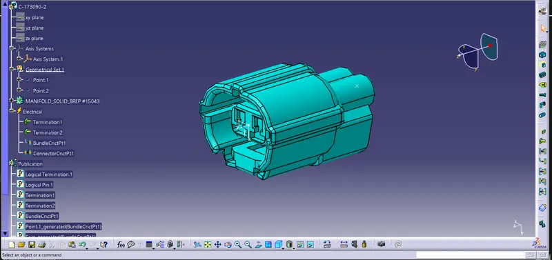
Defining the connectors ,electrically:-
(a).Connectors:-
1.
Part No : C-173090-2
No of terminals: 2
No of Quantity : 2
2.
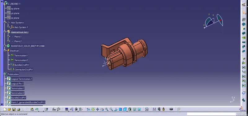
Part No : C-282080-1
No of terminals: 2
No of Quantity : 3
3.
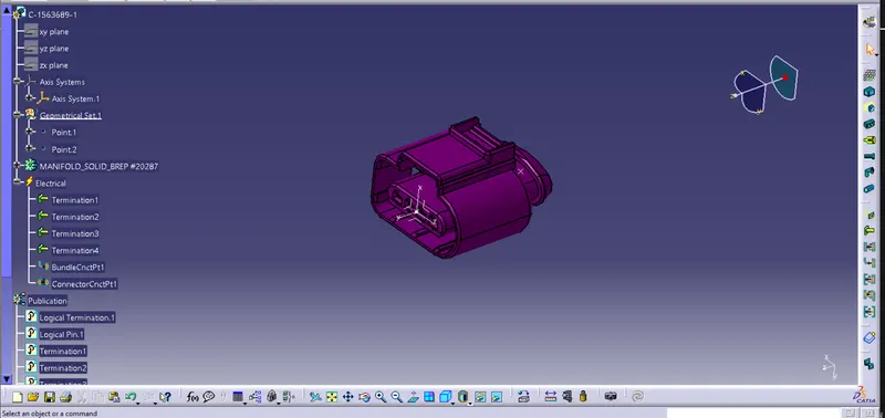
Part No : C-1563689-1
No of terminals: 4
No of Quantity : 20
4.
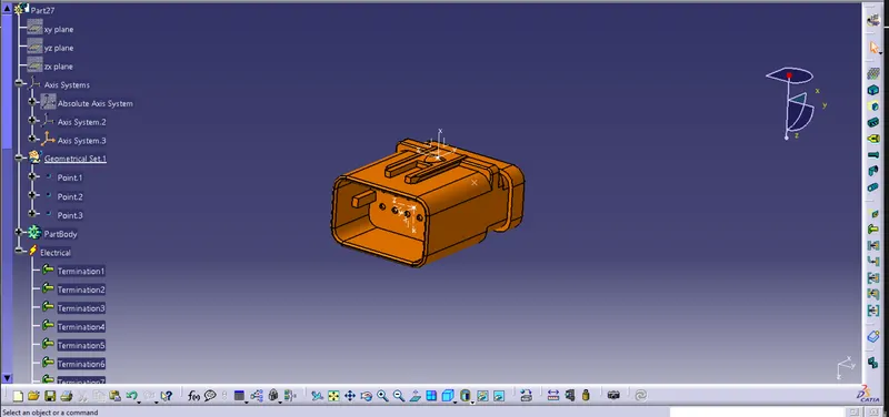
Part No : C-776438-4
No of terminals: 12
No of Quantity : 1
(b).Mounting Equipment:-
1.
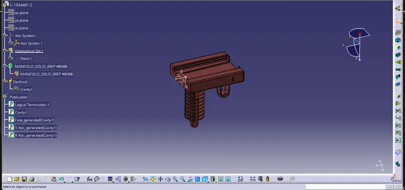
Part No : C-1924487-2
No of Quantity : 1
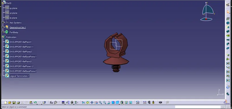
2. Furr Tree Clip:-
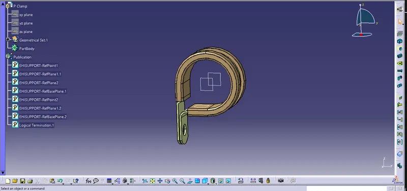
3. P Clamp:-
4. Channel:-
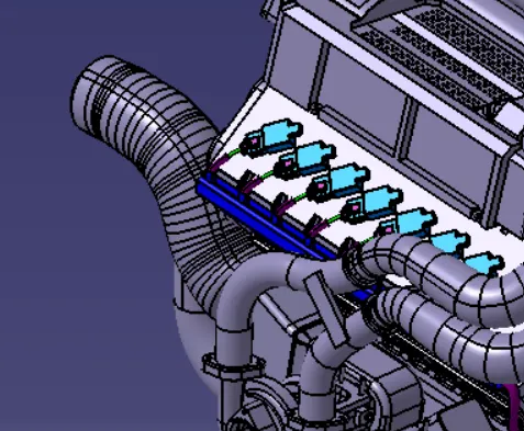
Adding connectors to all 16 fuel injectors sensor :-
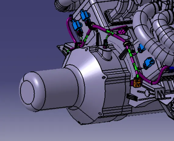
All the connectors have to be added inside the Engine harness geometrical bundle assembly. Manipulation tools along with a compass, snap, and smart move features should be used to locate all the 16 connectors in their desired locations. All the connectors are shown in red for clarity.
First, connectors are located for the first 8-fuel injector sensors which are on the left side of the engine. At last, the remaining 8 connectors are added to the 8 fuel-injectors on the right side of the engine.
Sheet-metal bracket for mounting interconnection connector:-
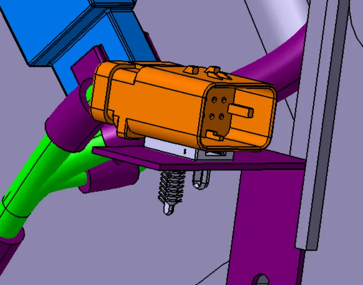
A sheet -metal bracket has to be created in order to provide mounting for the interconnection connector. We have to make sure that the bracket is placed inside the context assembly outside the engine and harness geometrical bundle assembly. The bracket can be mounted on the existing bolt located as shown below. It has to be made sure that in the real-world application if we are using any existing bolts or screws then the design idea has to be discussed and passed by the engine design engineering team in order to make sure the proper functioning of the engine. This bracket should have a locking feature in the clockwise-direction so it does not rotate freely. The current engine design has a rib feature as shown below which can be used to our advantage as a locking feature. The edge of the bracket will sit on the rib thus locking the bracket in place also placed the p-clamp and furr tree clip at specific location then start harnessing.

Harness Routing:-
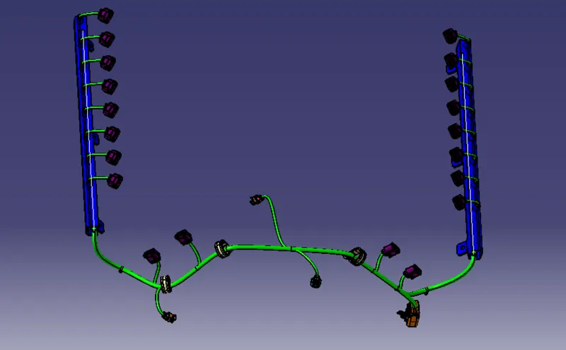
Checking Bubdle Continuity:-
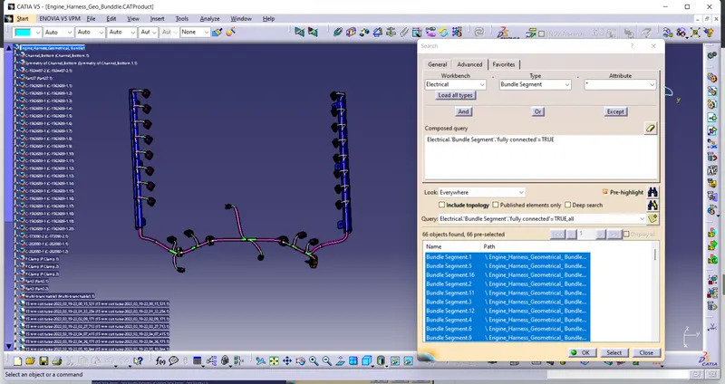
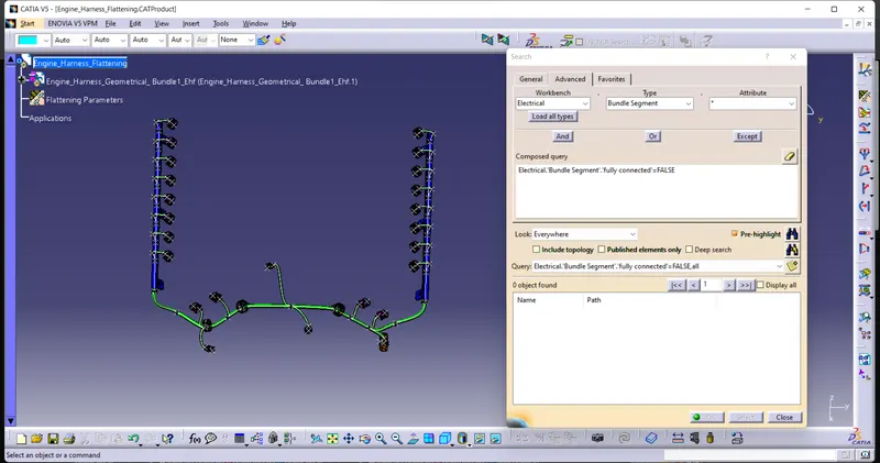
First, we have to make sure that multi branchable is selected and then we have to go in WORKBENCH>TYPE-BUNDLE
EDIT>SEARCH>ADVANCED>ELECTRICAL
SEGMENT>ATTRIBUTE-FULLY CONNECTED
Selecting the "TRUE" option will show all the connected bundle segments while the selecting "FALSE" will show all the non-connected bundle segments.
For now, we will select "TRUE" and "FALSE" both and search for results. All the bundle segments are highlighted and found showing that all the bundle segments are electrically connected.
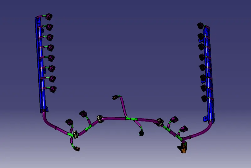
APPLICATION OF PROTECTIVE COVERINGS ON THE HARNESS :-
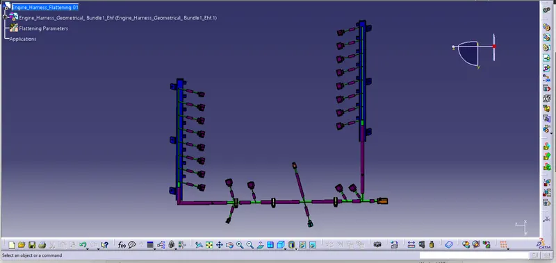
Create the electrical flattening of the geometrical bundle assembly:-
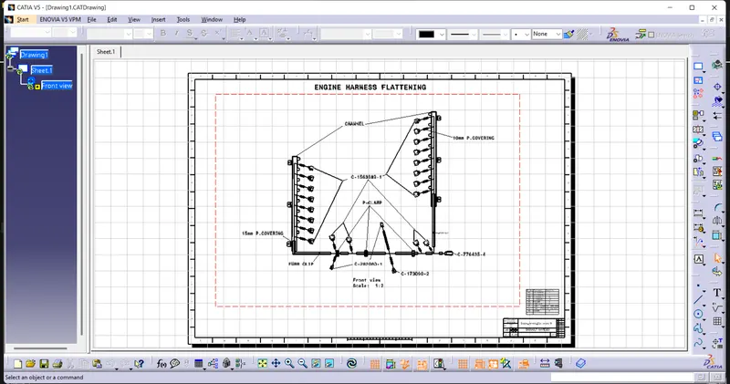
Create the 2D drawing file with all the details:-
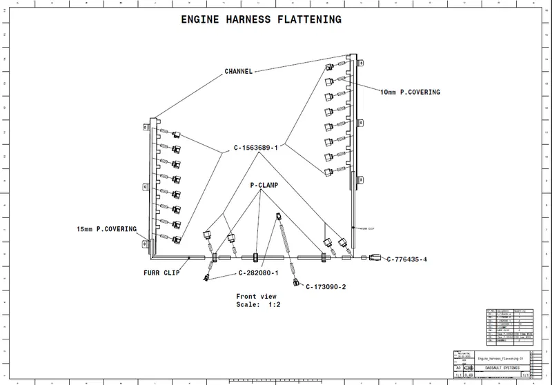
Screen Shot of Drawing Pdf:-
CONCLUSIONS:-
- The wiring harness basics and the industrial practices are studied.
- Different connectors and their installation in 3D modeling are practiced.
- The protective devices and their application at the required region in the wiring harness bundle are practiced.
- Electrical workbenches in CATIA V5 such as electrical part design, electrical assembly design, electrical assembly harness, electrical harness flattening are exercised.
- 3D representation and 2D drawing of the engine harness are implemented.
- Engine harness is taken as a case study and developed the geometrical bundle assembly without fouling the bundle segments.