Project 1
Statement of assignment:
Route the Wiring harness on Given Engine and Prepare flatten view drawing in CATIA V5. Application of all Packaging rules, Industry best practices studied in this course shall be demonstrated in design. Apply Protection coverings as required.
Available connector 3D data can be used, or you can download the connectors from www.te.com
Prepare & Submit all necessary reports like clearance, Clipping/Clamping selection, Harness fixing requirements, Harness continuity, Assumptions if any along with CATIA 3D data.
Engine cad data to be downloaded from www.grabcad.com
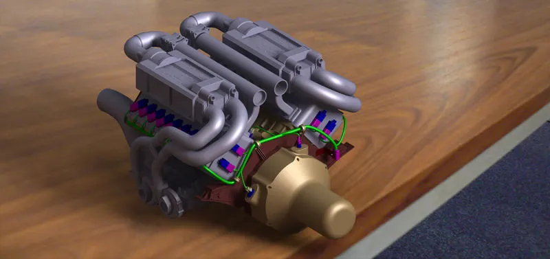
V16 Engine
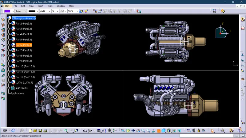
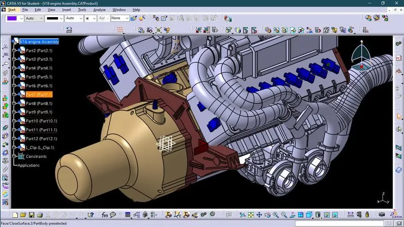
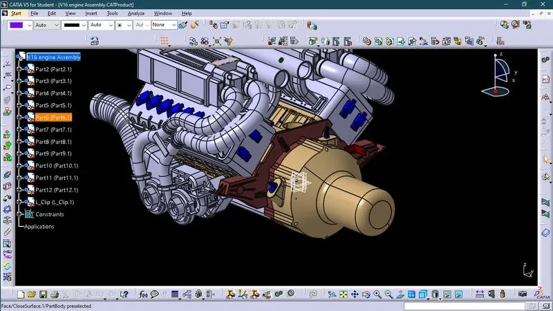
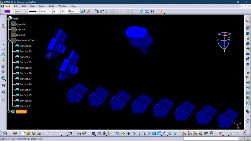
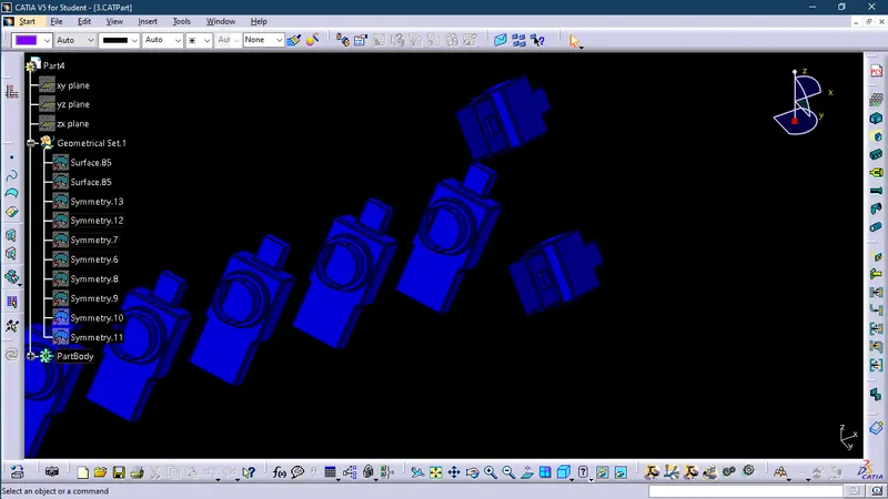
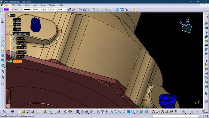
Following are the components required in wire harness assembly on engine
Channel
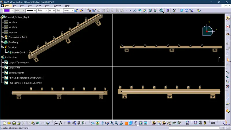
2-Pine Dummy Connector
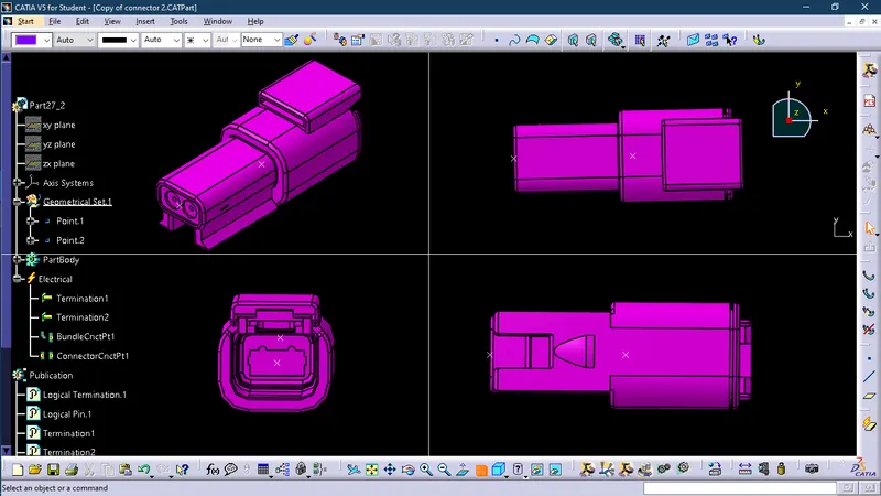
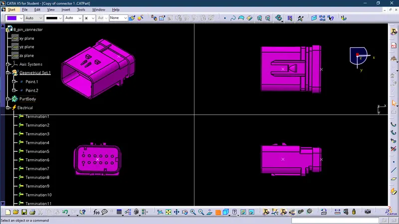
8-Pine Dummy Cinnector
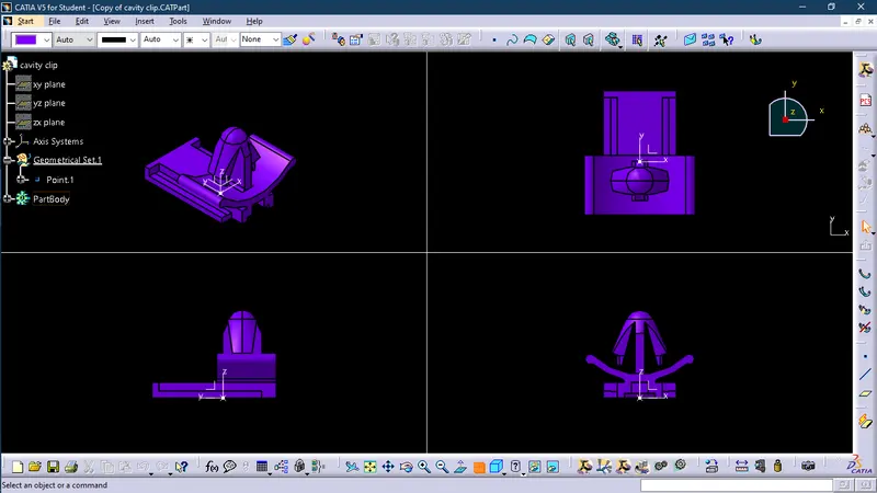
Cavity Clip
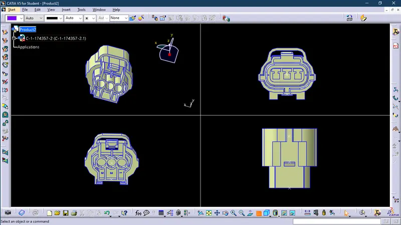
3-Pine Dummy Connector
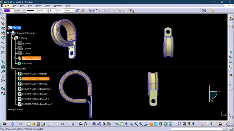
P-Clamp
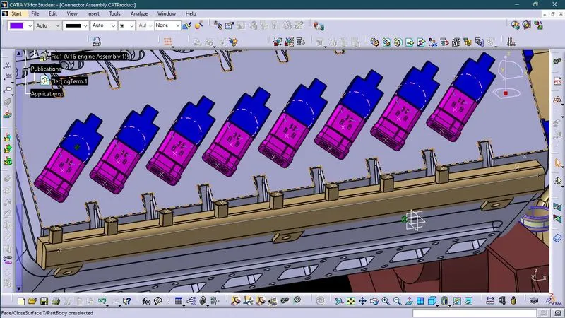
Connector Assembly
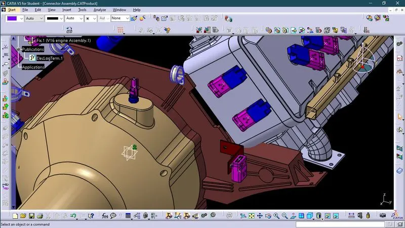
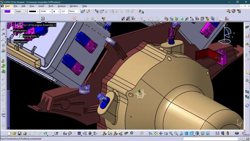
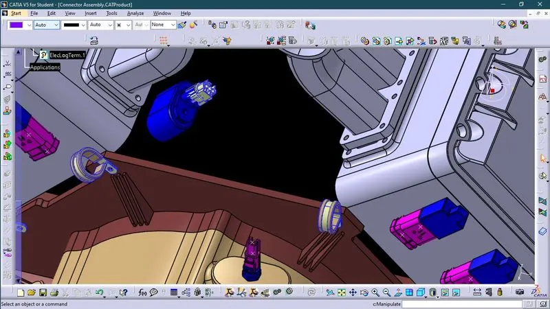
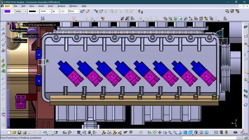
Wire Harness
Wiring harness product assembly contains-
The harness context assembly - this is the top level product file that contains the harness geometrical bundle/assembly and the wire harness electrical bundle.
Geometrical bundle - this sub level product file is the wire harness product that contains all of the harness components i.e., clips, supports, connectors, splices, grommets, annotation and actual physical bundle segments and branches.
Electrical bundle - this sub level product file contains all of the electrical circuit information.
Factors necessary for wire harness on V16 engine
1. Clearance management
2. Water Ingress Protection
3. Thermal Protection Management
4. Chaffling Protection
5. Vibration Protection
6. Routing on/Near Dynamic Parts (Engine, Wheel)
7. Harness Bending Basic (Harness and Battery Cables)
8. Interconnection Connector Parking
Procedure
First we will Download connector 3D data and then convert them into electrical connector and then add them into catalogue as aconnector.
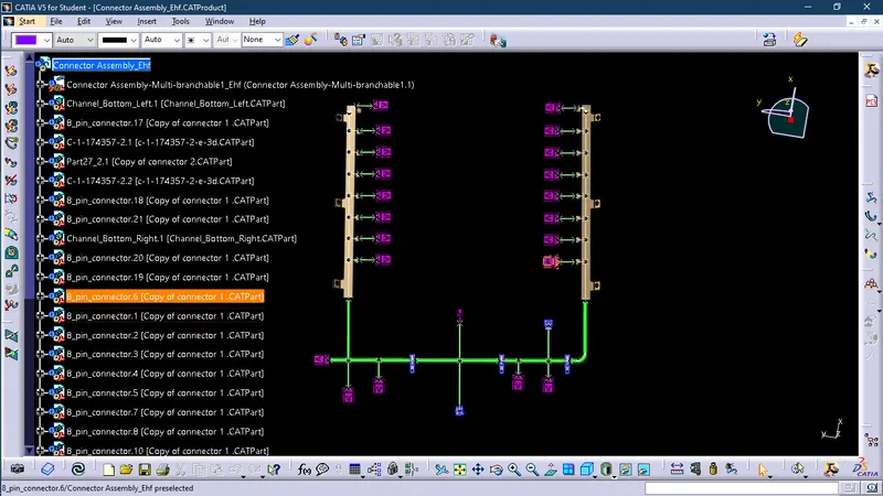
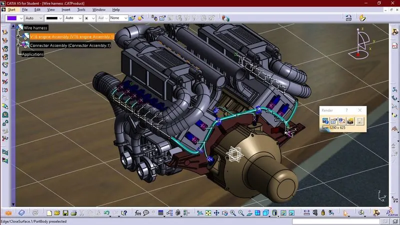
Now we will create wire harnesses by using electrical harness assembly. In this we will proceed in following ways:_
a. Open the Electrical harness assembly workbench.
b. Insert the pre-defined connectors either through insert command or using catalog.

c. Now we will arrange different connectors in the way that is pre-defined in the challenge schematic by using the manipulation command in assembly workbench.
d. Now define product as Geometrical bundle.

e. Now we will use multi branchable document to create wire harness to connect different electrical connectors.

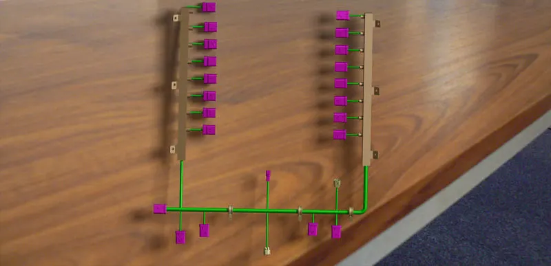
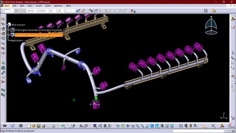
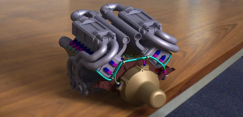
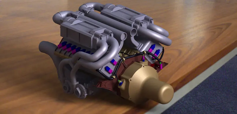
f. Now we will apply protect covering on wire harness by using protective covering.

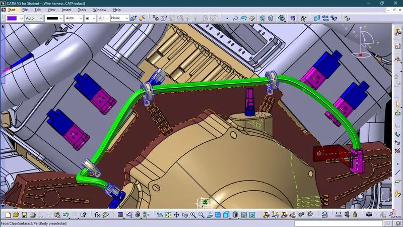
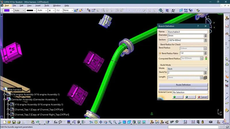
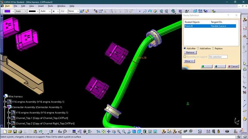
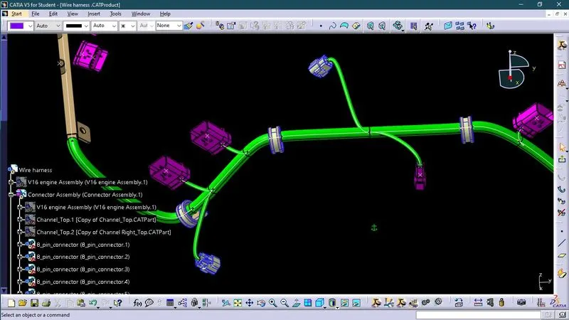
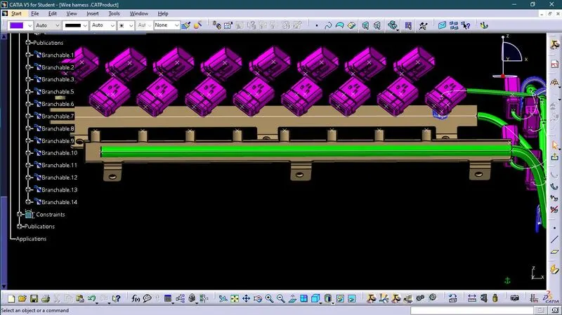
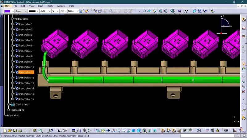
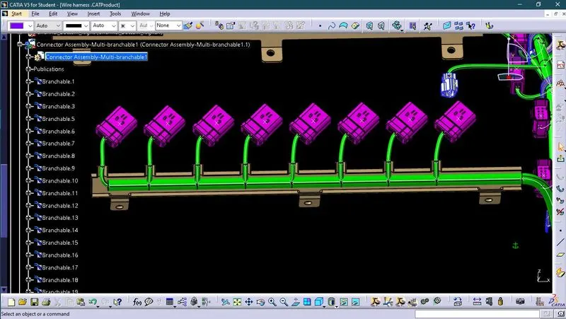
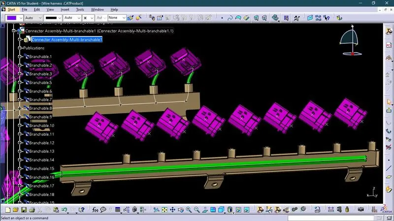
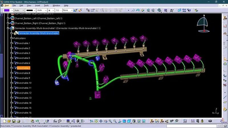
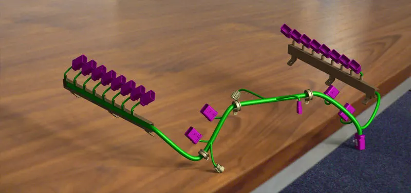
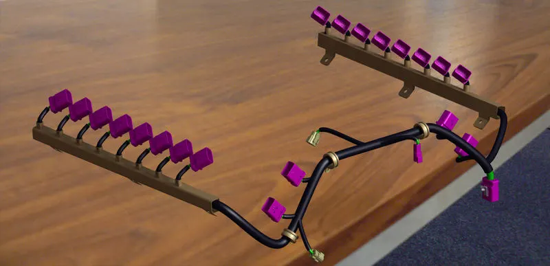
Wire Harness with protective covering
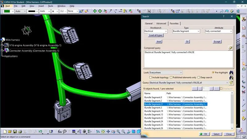
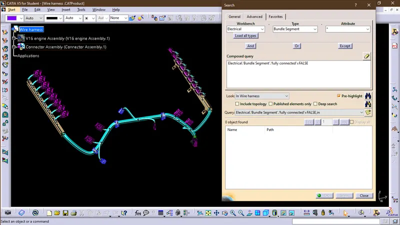
Connectivity check
Then we will check the connectivity of the wire harness by using search command
when we put attribute criterion fully connected = FALSE , it will give a list segments which are not connected or showing error, if any arries
when we put attribute criterion fully connected = TRUE , it will give a list segments which are properly connected.
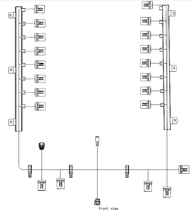
Wire Harness Flatening
Flattened view
- WE GO TO THE HARNESS FLATTENING WORKBENCH AND DEFINE THE FLATTENING PARAMETERS.
- WE USE THE EXTRACT COMMAND TO BRING THE HARNESS ASSEMBLY TO THE FLATTENING WORKBENCH HERE.
- CHOOSING A SUITABLE PLANE WE FLATTEN THE HARNESS ASSEMBLY.
- BUNDLE SEGMENTS ARE ROTATED AT THE REQUIRED ANGLES. THE HARNESS ASSEMBLY IS THEN DRAFTED.
- FLATTENING PARAMETERS ARE DEFINED IN ORDER TO MAKE THE BUNDLE AND THE CORRUGATED TUBES VISIBLE IN THE 3D DRAWINGS.