Project 1
Aim:
- To create mold blocks for the table fan stand.
- To create the ejectore pins
- To create sliders and undercuts for the door bezel mold block.
Procedure:
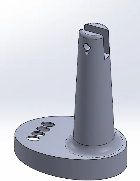
- Analyse the component and decide the tooling direction for the mold design.
- Then perform draft analysis to check whether the drafts provided component surface are with the limits for easy removal of part from the core and cavity blocks.
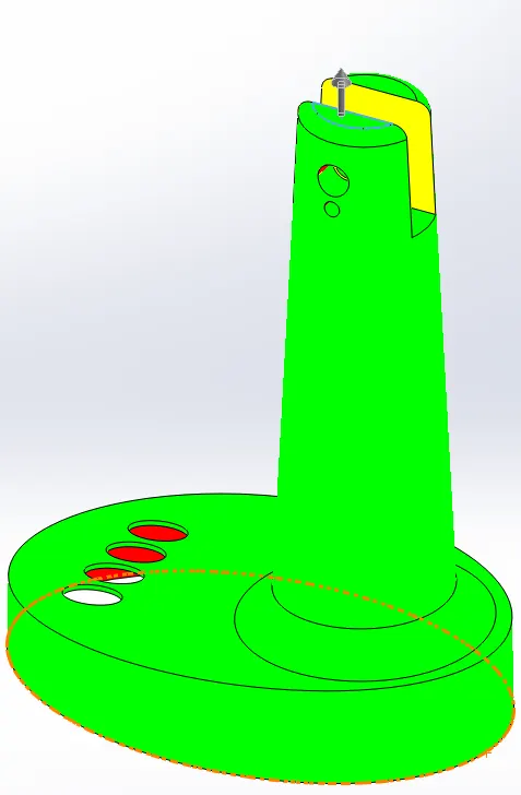
- Select any surface perpendicular to the tooling direction for draft analyis.
- The draft analysis result should show 2 coloured region, the positive draft will be in Green colour and negative draft surface in red colour.
- These 2 regions represent the surface for the core and cavity blocks.
- We can see that there a small region in the model as shown requires a undercut because it cant be created in two blocks.
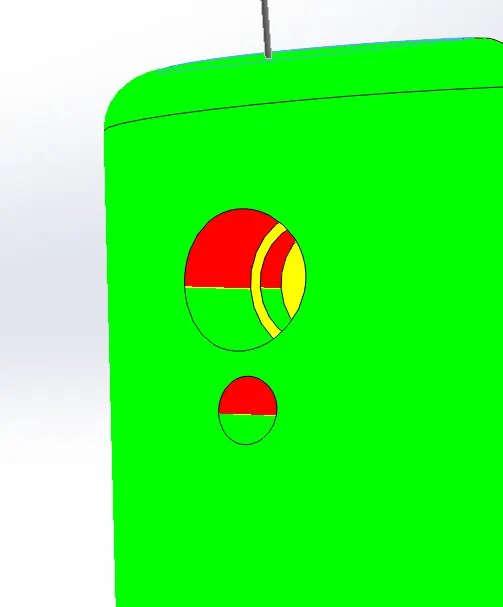
- Increase the scale of the component to 1.006 i.ie., considering the shrinkage of the material is 0.6%
- Next we have to create parting line.
- Click parting line from mold design menu and click surface with was earlier delected for draft analysis and click show result.
- The parting line is now created.
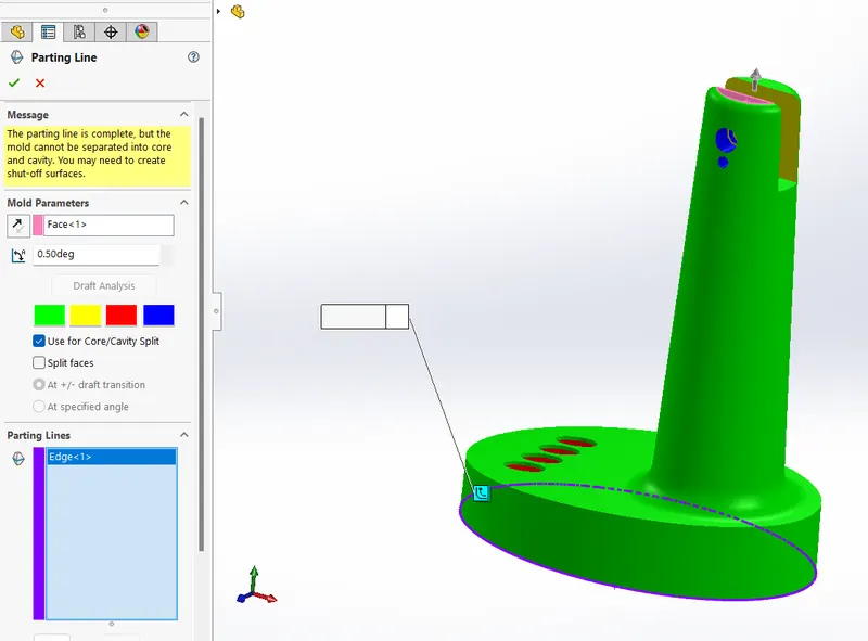
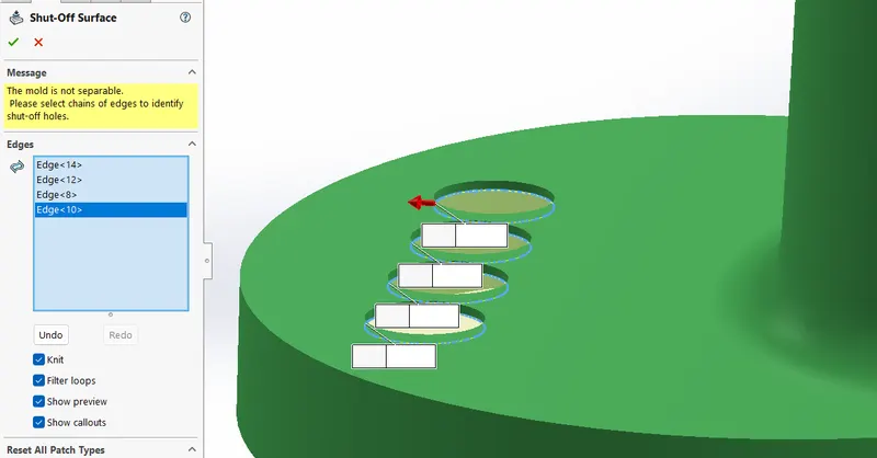
- Now click shut-off surface option and then select the region / edges which closes the hole profiles.
- A shut-off surface closes up a through hole by creating a surface patch along a parting line or edges that form a continuous loop.
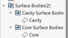
- 2 surfaces will be create, one will be core surface and other will be cavity surface.
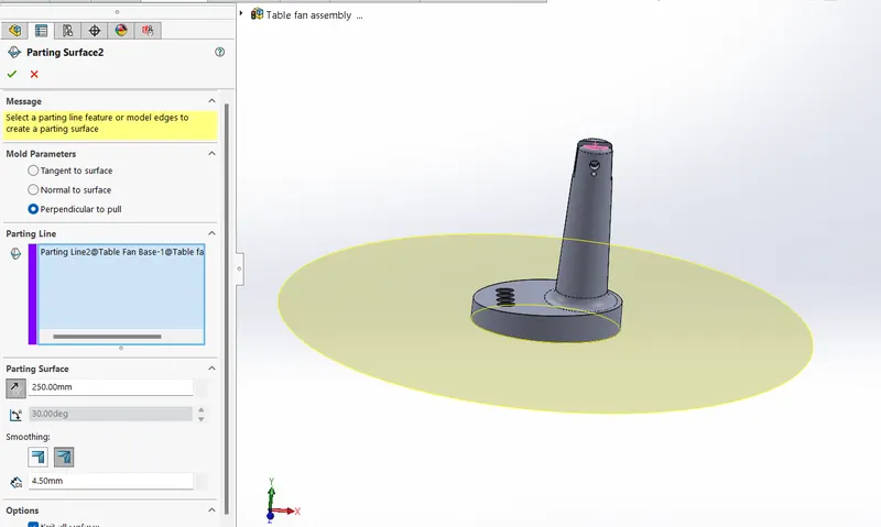
- Create a parting surface surface using the parting line.
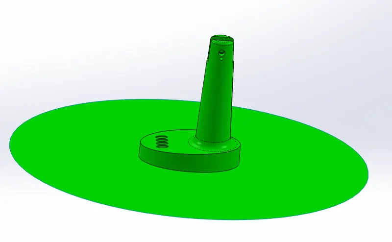
- Now using knit surface command merge the cavity surface with one planar surface and similar the other planar surface with core surafce.
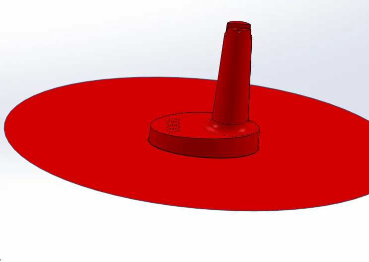
- Since the core and cavity surfaces are created, now it should converted to blocks.
- From here on we will be creating the the core and cavity block in two different part files and merging all in single assembly file.
- Now all the work will be done in assembly workbench.
- Create 2 seperacte part files as shwon below.

- Adjust the car door bezel and match the origin of the assembly to the origin if the car bezel file.
- The origin of the bezel should be at the sprue location always. and fix the compoenent.
- Select the core block file and enable edit component command.
- Create the retangular sketch and extrude to appropriate distance both the directions.
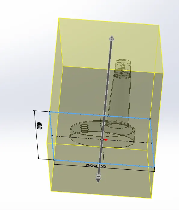
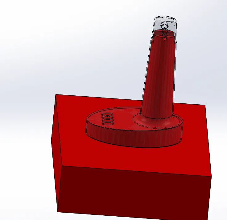
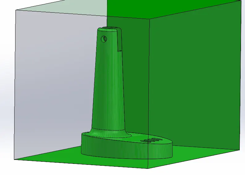
- Now using cut with surface, cut the unwanted region with reference to the core and cavity surface one by one seperately as shown in below image.
- The core and cavity blocks are created.
- Next we have to create the ejector pins and inserts for the core block.
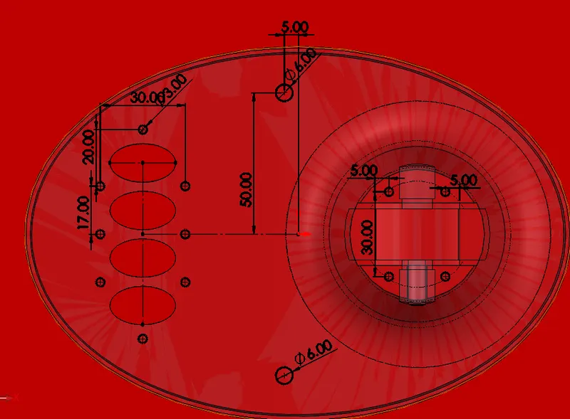
- In order to create the ejector pin draw a circles of diameter 3mm and 6mm (considering 3mm and 6mm ejector pin) on the bottom plane as shown in the figure
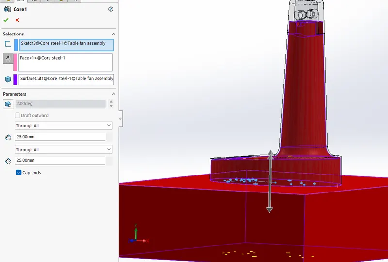
- Click create core command in the mold design menu and select the sketch and click the option for distance as through all.
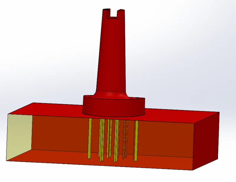
- Now new solid bodies will be creates as shown below. change the apprearance to yellow colour for the ejector pins.
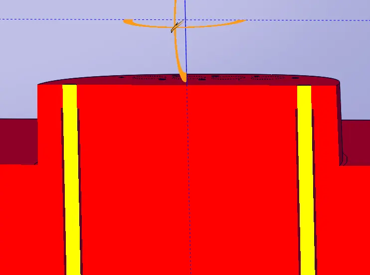
- Draw a sketch again in the same surface for the relief of the ejector pins.
- The circle diameter should be 3.95mm and 6.9mm as shown below.
Plan to create the sliders:
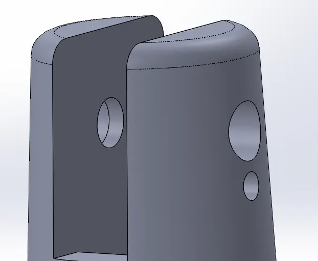
- When we use only core and cavity block and the material solidifies, it will be impossible to seperate the cavity bloch because of the uncut region as shown above.
- Here sliders should be created for this undercut section.
- We can see that ghe undercut region is on the cavity block.
- In the below sectional image the region within the yellow line will be the slider location / crossection.
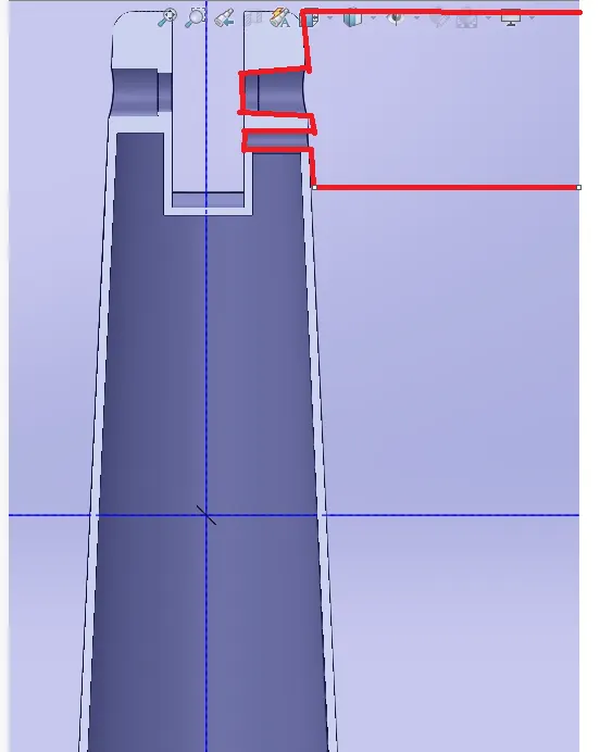
The movement of the slider will in horizontal direction in right to left direction once the material is solidified. First the core block is seperated anf then the slider block will be removed.
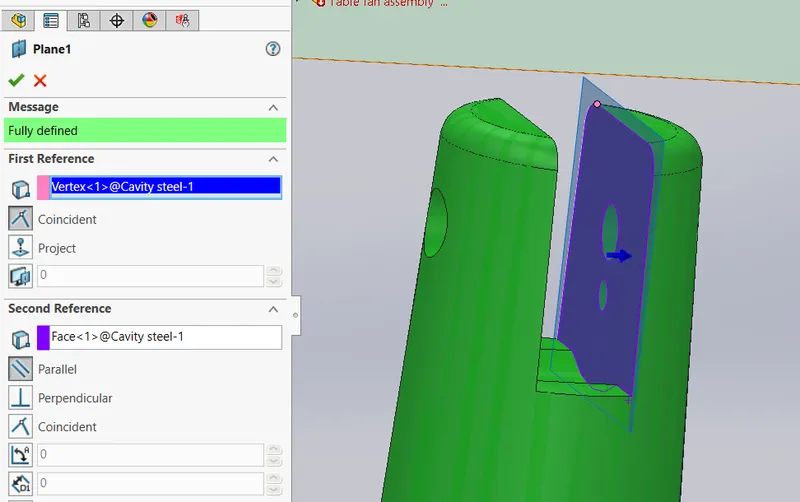
- Activate the cavity block first, then create a reference plane with edges to choose as reference as shown below,
- One the reference plane draw a sketch.
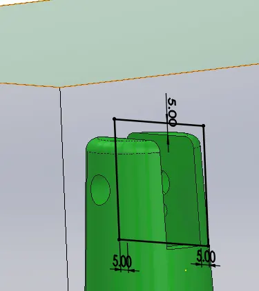
- Click split command and select the reference plane and the sketch created as the trim / split tool and the for the body select the cavity block and click cut bodies.
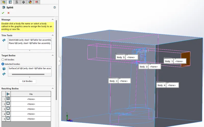
- Now from the list of resulting bodies select the body needed to be split up and deselect consume cut bodies option and click 'OK'.
- Now here 2 seperate bodies are created. So in every step show take care about choosing the feature scope as necessary.
Similary create a rectangle sketch on the top surface of the slider body and extrude till bottom surface.
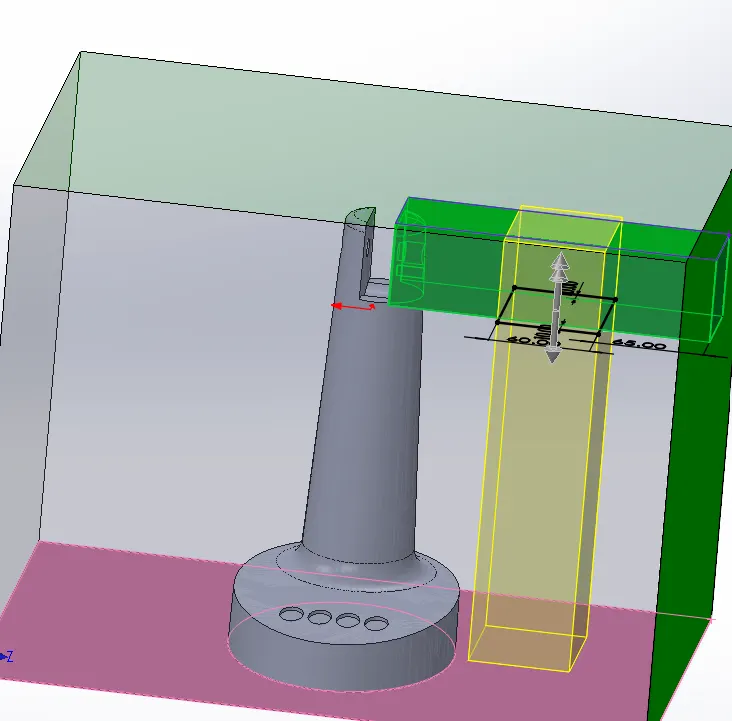
Create a chamfer of the edge of the slider solid for the easy removal of the cavity block.
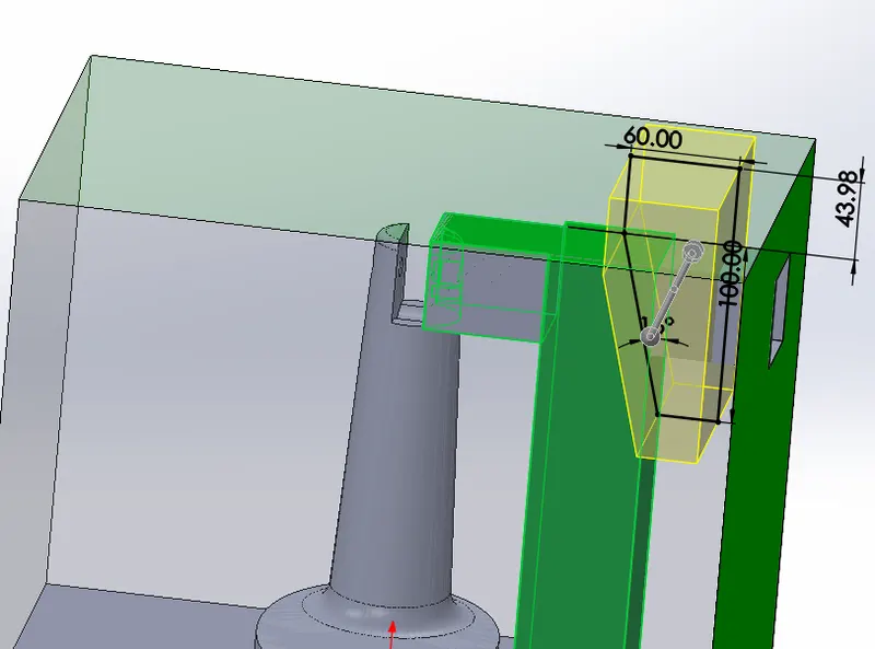
Extrude a region as shown below to the cavity block
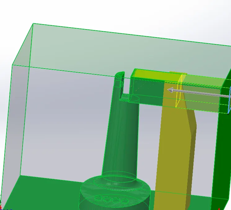
Create a copy of the slider block and then using combine command subtract the region from the cavity block.
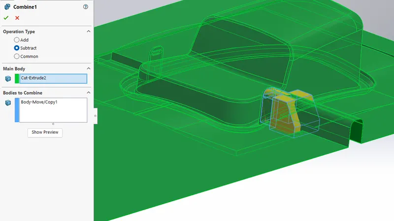
Right click the slider block from the feature tree, click insert in new part file and save it as a parasolid file for further steps.
Now create new part in the assemble and name it as slider.
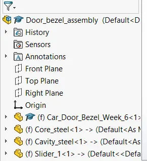
Import the parasolid part created and save the file.
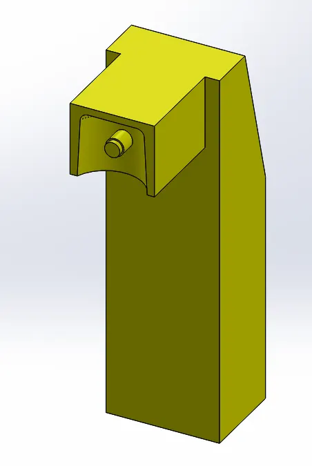
Now create a sketch on the top surface and cut the region leaving 10mm from the bottom surface.
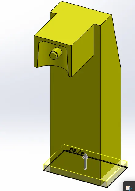
Create the fillet on the sharp edges which meets the cavity block of sizes, 2mm and 5mm.
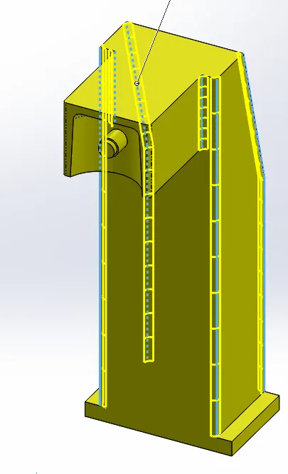
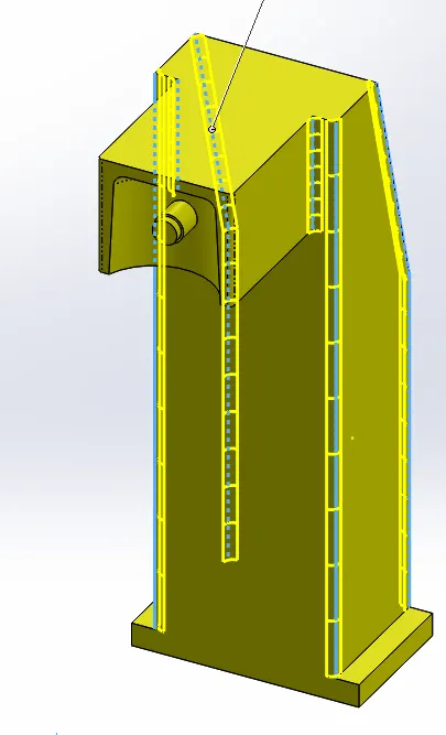
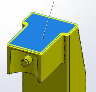
Again create a parasolid file of the slider block and save it.
Activate the core block for editing draw 2 rectangles and extrude them to 10mm.
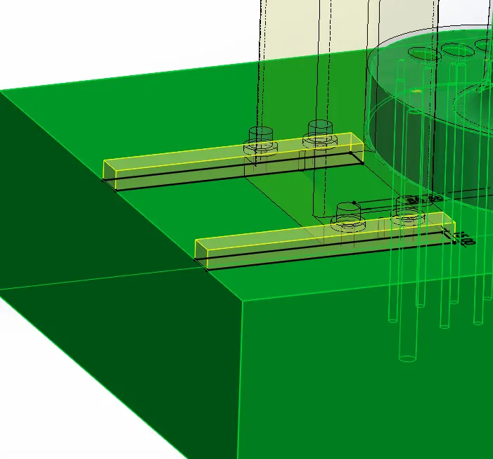
The region will act as a guide for the movement of slider block.
Make a cut as shown below on the core block and slider block such it acts as a locking mechanism for the slider block.
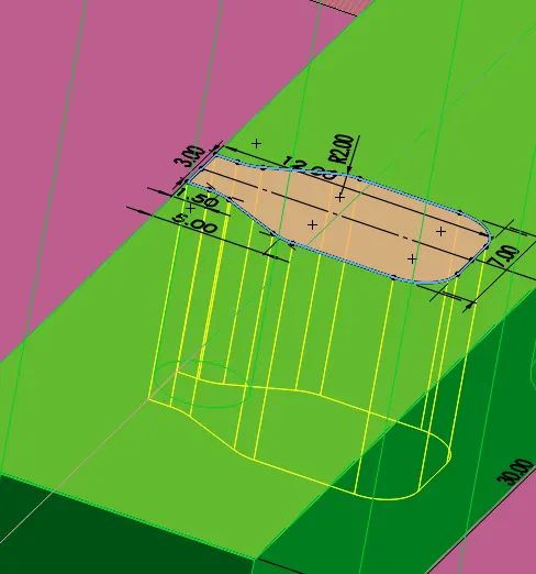
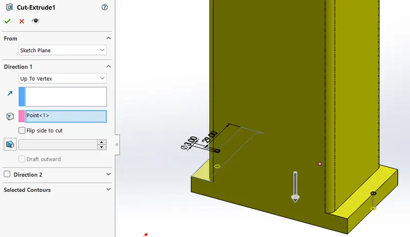
Next we have to create washers and bolts for the fixment of the slider.
Create new part file and draw a circular sketch as shwon below and extrude to 3mm.
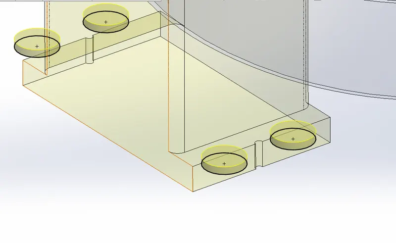
These is the washers and change the colour to grey to distinguisd between the washer and bolts.
Similarly create the bolts and make sure that the merge entites is deselect.
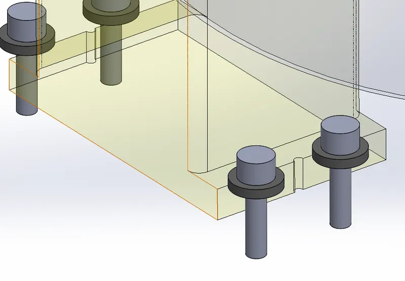
Create a sketch of point at appropriate locations. Using sketch driven feature create the remaning bolts.
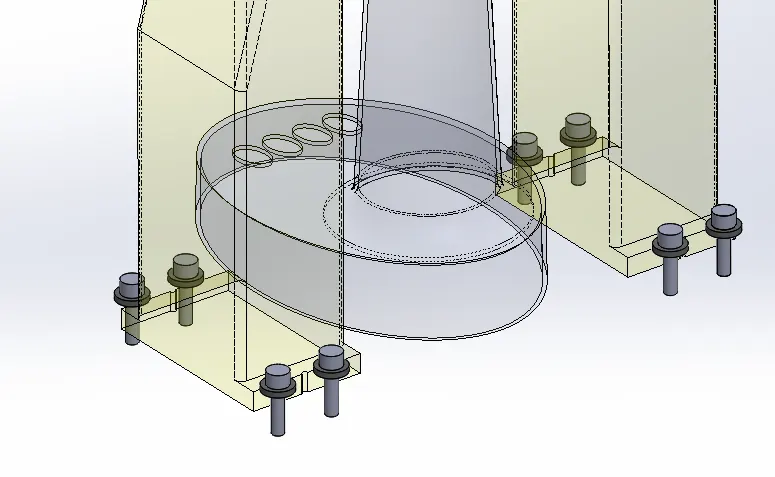
Now we have to create the tap hole on the core block for the bolts.
Click hole wizard, seletch the tap hole option and select the types as M6x1 hole and click position tab.
Click 3d sketch, and select the point of the bolt for the creation of the threaded hole. Next pattern ans mirror the hole at respective places.
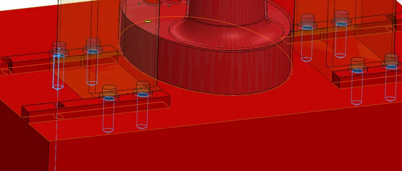
Activate the cavity block file for editing.
Draw a rectangle on the blottom plane and extrude cut upto vertex option and select the edge of the core block.
Import the newly saved parasolid file and using combine option subtract the region from the cavity block.
Create fillets at siimilar edges as created in slider block. Fill the unwanted region using extrude command.
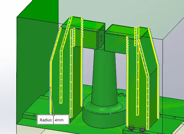
Now we have to create a relief for the bolt head as shown in below image.
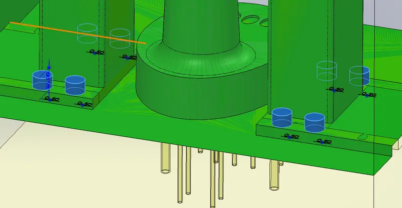
Simlarly create another slider block and various entities for the other side of the cavity block using the above procedure.
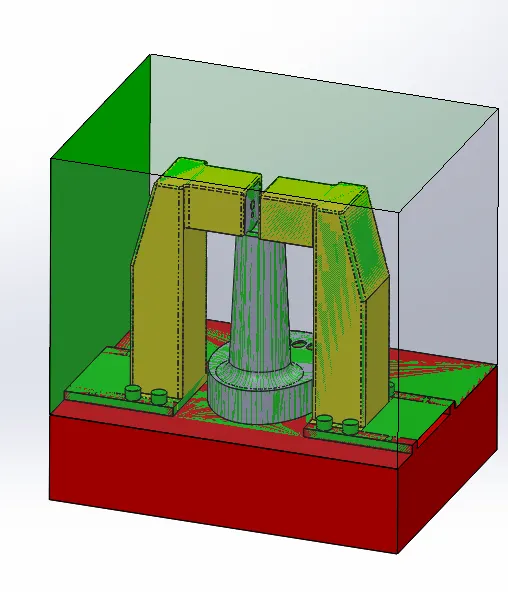
Conclusion:
The various features like cavity blocks, core block, undercuts, sliders and washers are created for the Table fan stand.