Project 1
Automotive Wiring Harness using CATIA V5 - Challenges
Project 1
Statement of assignment:-
Route the Wiring harness on Given Engine and Prepare to flatten the view drawing in CATIA V5. Application of all Packaging rules, Industry best practices studied in this course shall be demonstrated in design. Apply Protection coverings as required.
Available connector 3D data can be used, or can download the connectors from www.te.com
Prepare & Submit all necessary reports like clearance, Clipping/Clamping selection, Harness fixing requirements, Harness continuity, and Assumptions, along with CATIA 3D data.
Solution:-
The wiring harness procedure is followed to route the wiring harness on the given 3D engine data. A 2D drawing of the harness is also prepared after flattening the harness, following packaging rules like the distance between the branch point and connectors of a bundle segment, slack for the end connector, and clearance of the harness with the help of clips and clamps.
Wiring Harness Procedure:
- Identify the Harness assembly component
- Define all Harness assemblies as Electrical
- Prepare Harness assembly
- Define assembly as Electrical Assembly
- Change/Customize tool sets as required
- Start Routing the bundles following the Packaging guidelines
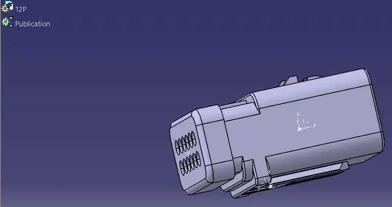
Connector Definition
- Download 3D Connector
Mechanical Part Design Workbench -
- Defining Geometrical Parameters (Points and Axis system)
1. Bundle entry side center point
Selecting required random points to get a center point for a suitable point type.
2. Mating side center point
Selecting required random points to get a center point for a suitable point type.
3. Mating side axis system
Creating an axis system concerning the center point as the origin of the axis. The Y axis is directed at the mating direction, the X axis is directed towards the locking side and the Z axis is directed upwards.
Electrical Part Design Workbench -
- Define part as Connector
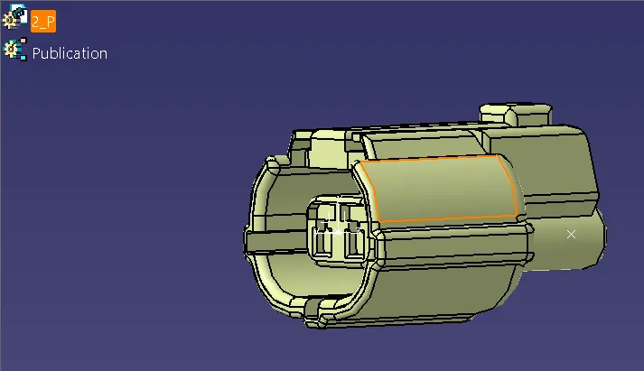
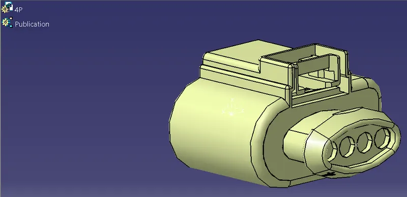
Defining part as an electrical connector in Electrical Part Design Workbench using 'Define Connector', and also selecting the number of terminations for the connector.
- Define Bundle Connection Point
Defining bundle connection point at the bundle entry side where representation is the face of the side, point as the center point, and initial condition also as the face of the side.
- Define Connector Connection Point
Defining connector connection point at the mating side of the connector where representation is the center point, contact is the face of the side, coincidence is the Y axis, and, orientation is the X axis.
- Define cavity connection point (if connector needs mounting clip)
A cavity connection is defined as the connecting part for a connector clip where representation is the center point of the cavity connection, contact is the connection face, coincidence is the Y axis and, orientation is the X axis.
A catalog is also been created for all the electrical components and can be used for the Geometrical bundle assembly, through 'Catalog Browser'.
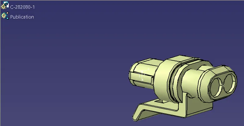
Mounting Clip Definition
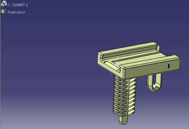
- Download 3D part
- Defining geometrical properties (points and axis system)
1. Mounting clip center point
Selecting the edge of the connecting part to get a center point, under point type curve.
2. Mounting clip axis system
Creating an axis system for the cavity, the origin is the center point, the Y axis is directed towards the insertion, the X axis is directed upwards and, the Z axis is directed to the side. The axis direction should follow the connector's cavity connection axis direction for proper mounting.
Electrical Part Design Workbench -
- Define part as a Mounting Equipment
The clip is defined as electrical mounting equipment.
- Defining Cavity
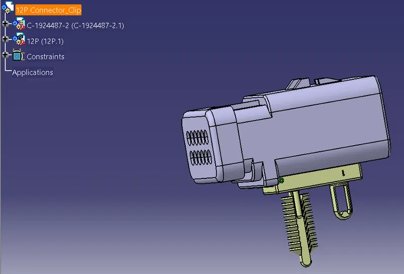
- Connect Electrical Devices
The connector and connector clip are connected in the electrical assembly design workbench using 'Connect Electrical Devices'.
The components used as sensors or dummy connectors are electrically defined by following the same steps for defining the connectors.
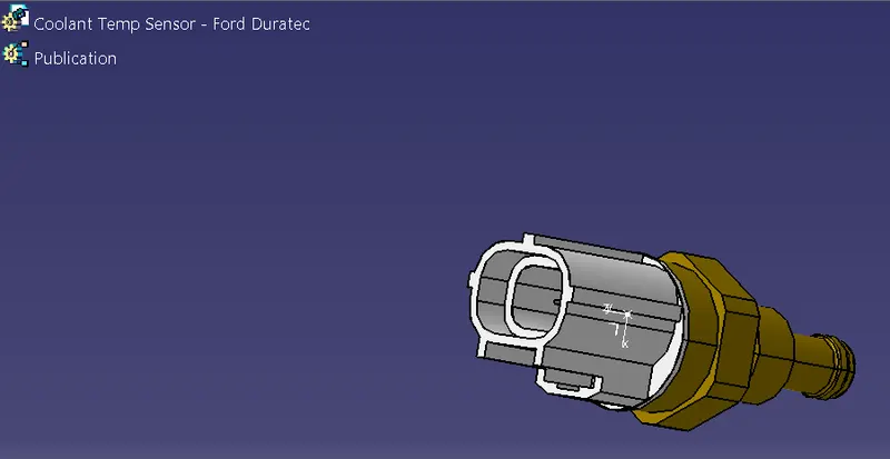
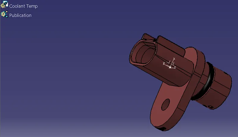
Clip/Clamp Definition
- Get the Clip/Clamp 3D part
Mechanical Part Design Workbench -
- Define the Geometry Parameters
1. Points and Planes
Defining the points for both sides through point definition.
2. Creating entry, exit, and base planes through plane definition.
Electrical Part Design Workbench -
- Define part as support
The support definition for the clip/clamp is defined twice to make bilateral connectivity. The point selected for the side will be the entry side of the bundle, which is done for both sides. The entry point & plane, base & exit plane is defined in the support definition.
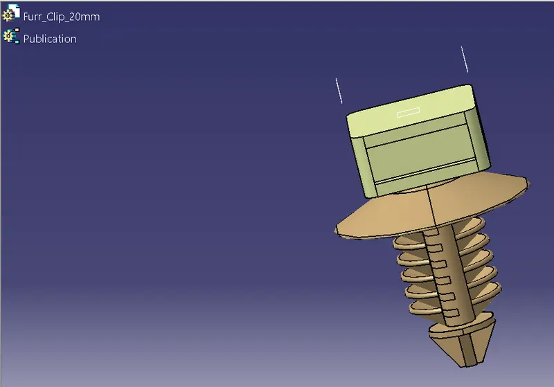
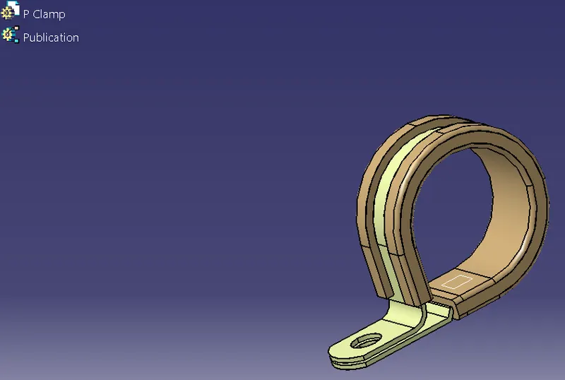
Guiding Channel Definition
- Download 3D part
- Defining geometrical properties (points and curves)
1. Bundle entry side center point
Selecting required random points to get a center point for a suitable point type.
2. Line Definition
Defining the line for the required curve using line type Point-Direction and managing the length of the curve in Start and End in line definition.
Electrical Part Design Workbench -
- Define part as Equipment
Defining part as an electrical component in Electrical Part Design Workbench using 'Define Equipment'.
- Define Bundle Connection Point
Defining bundle connection point at the bundle entry side where representation is the face of the side, point as the center point, and initial condition also as the face of the side.
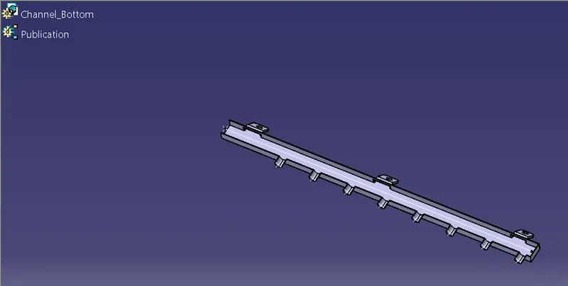
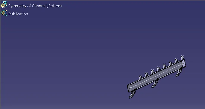
Mechanical Assembly Design Workbench -
- Symmetry
Assembly Symmetry Wizard
1. Select the symmetry plane
2. Select the product to be transformed
Preparation of the Harness Assembly
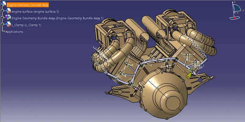
1. Harness Context Assembly
All the supportive context and Geometrical Bundle Assembly are the components of the harness context assembly.
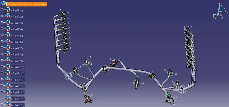
2. Geometrical Bundle
Mechanical Assembly Design
- Catalog Browser
All the electrical connectors are loaded in the geometrical bundle using Catalog Browser from their catalog. Manipulation, Snap, and Compass are the tools used from the mechanical assembly design workbench to place the connectors at the desired positions of the sketch.
Electrical Harness Assembly
- Geometric Bundle
The geometric Bundle command is used to electrify the geometrical bundle.
- Multi-Branchable Document
The multi-Branchable Document command is used to initiate branches for the electrical components using Branch Definition.
Electrical Harness Installation
- Branch Definition
The Branch Definition command is used to define the branches between the components. Branch diameter, Bend Radius (ratio 1.4), and Build Mode (slack) are set in the branch definition before proceeding with the Route Definition.
In Route Definition, objects/components are selected for which the branches are to be made.
- Add Branch Point
Branch points are created from the main branch using Add Branch Point command. The branch is selected for which the branch point is to be created and distance is defined as per the packaging guidelines for the branch point. New branches can be created through the same branch point.
- Protective Covering
Protective covering (COT Tubes) on all branches are connected with the end extremity of 30/20mm (from the end of the connector). Bundle segments are selected then the protective coverings are implemented using the COT Tubes catalog.
Bundle Continuity
- Edit
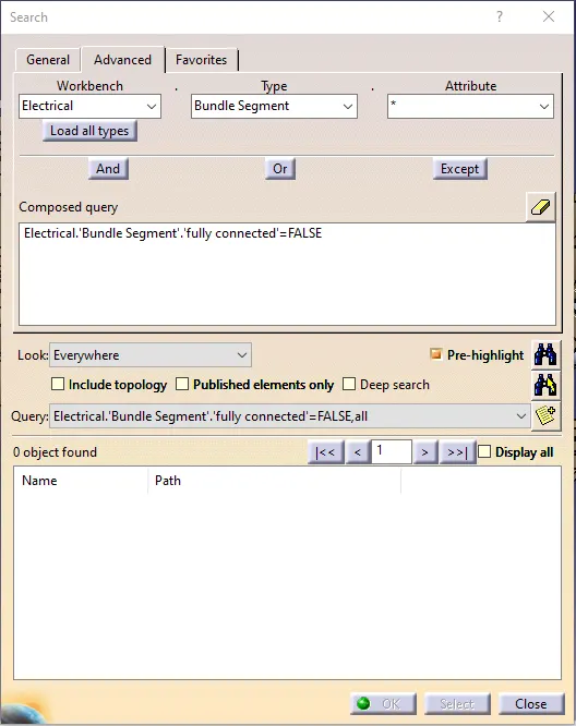
Bundle Continuity is checked for bundle segment for fully connected.
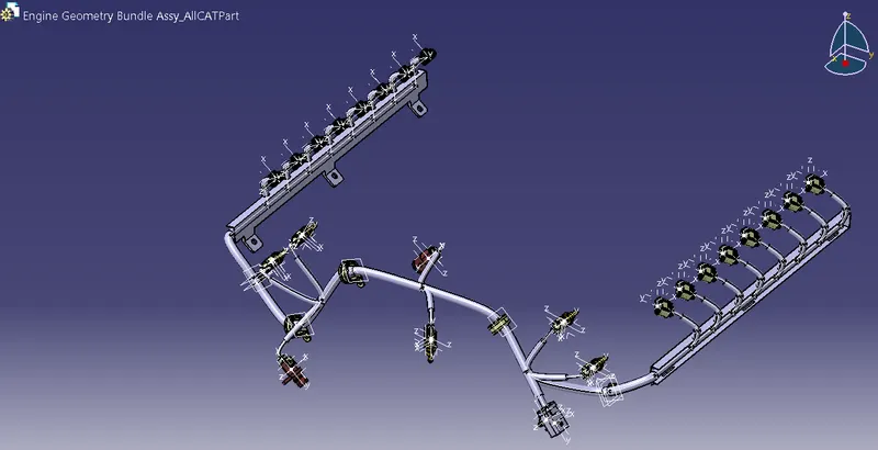
CATPart of Harness Assembly
Mechanical Assembly Design Workbench -
Tools
- Generate CATPart from the Product
Generate CATPart from Product is used from Tools to convert the CATProduct to ALLCATPart and then the same file is saved using save as in .igs format.
Electrical Harness Flattening
Creating a new product in electrical harness flattening workbench for the flattening process.
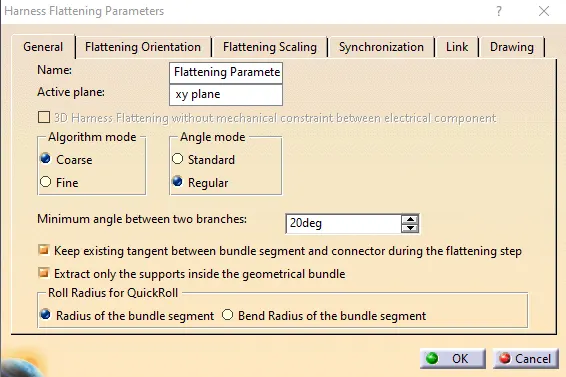
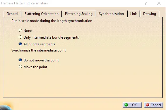
- Harness Flattening parameters
Defining all the necessary parameters for harness flattening.
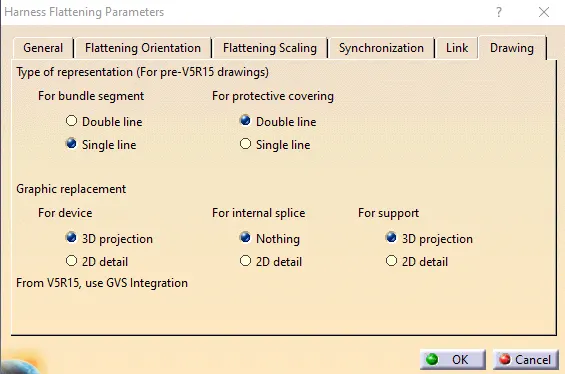
- Extract
Selecting an electrically defined geometrical bundle assembly for flattening.
- Flatten
Selecting the active plane for the harness flattening and selecting all the branches of the harness assembly.
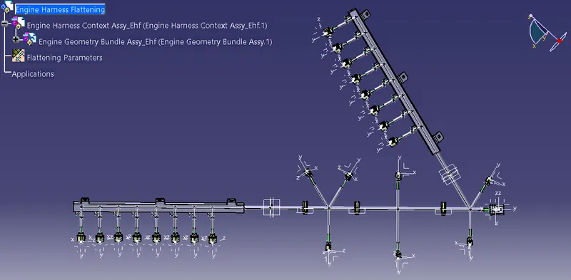
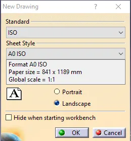
Drafting
Creating a new drawing in the drafting workbench, applying the below standard and sheet style.
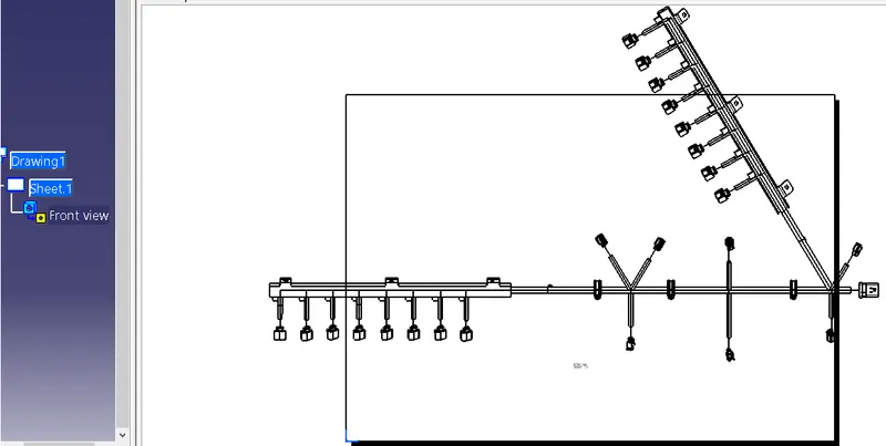
- Front View
Selecting the front view of the electrical harness flattening for drawing.
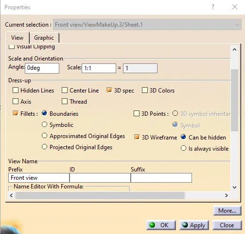
Updating the front view drawing parameters to get a proper 2D drawing for the electrical harness flattening.