Project 1
-> Analyze and design a steel building to 10T CRANE as per IS standard code in TEKLA STRUCTURAL DESIGNER. Refer the attached plan and elevation. Provide bracings and moment connection for lateral stability.
->Consider dead, live, equipment and wind loading. Consider the brick wall loading for 150mm thick and 1.5 KN per sq m for wall and roof cladding.
->Assume wind loading basic speed as 39m/s
Ans)
Aim: To analyze and design a steel building to 10T CRANE as per IS standard code.
Tools Required:
-> Tekla model
-> Construction levels
-> Properties
-> Grids
-> Coulmns
-> Beams
-> Rafter
-> braces
-> panels
->Validate
Procedure:
- Firstly we have to draft the beams and columns of the given design in the paint window.
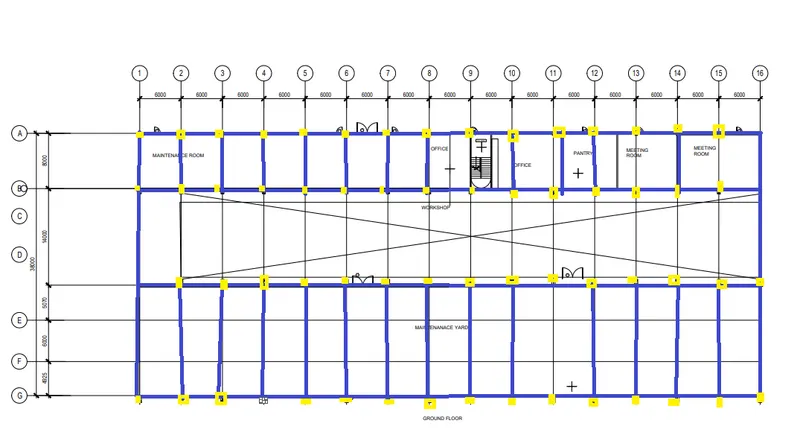
- Now open a new telka file and name it as Project 1.
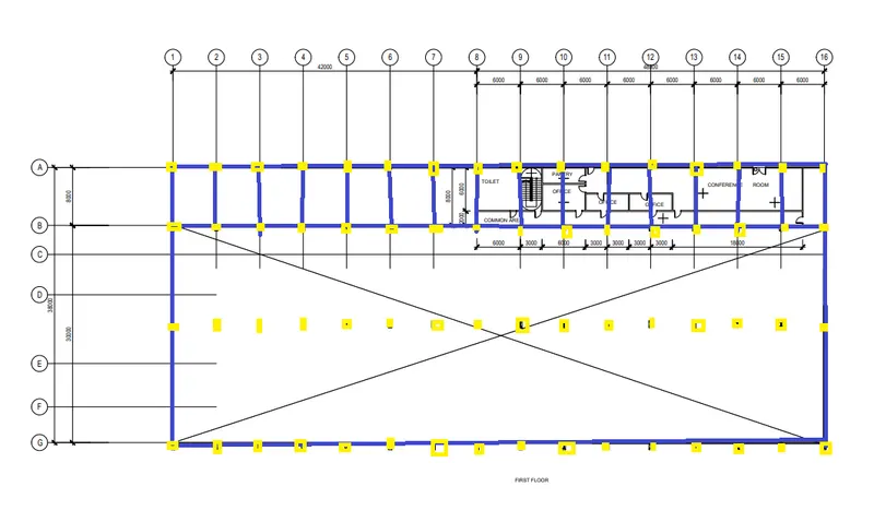
- Now that we are done with the saving part start to develop levels for the model that is given in the attachement.
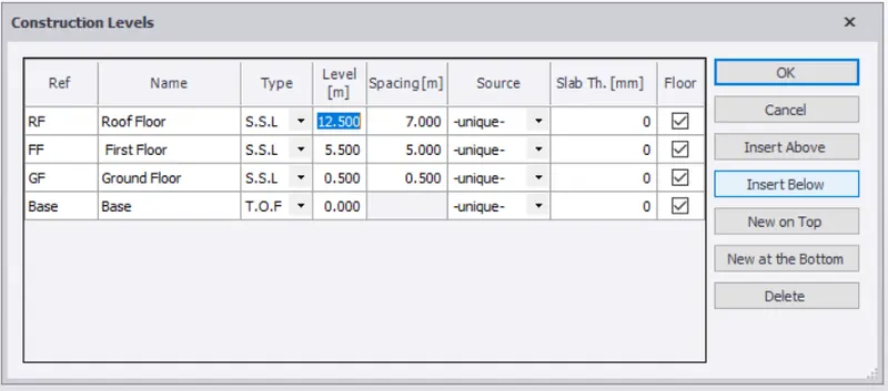
- Name the levels as Fisrt floor, ground floor,roof and the base and give the appropriate level spacing as shown in the attachement.
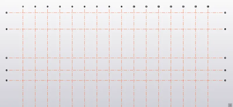
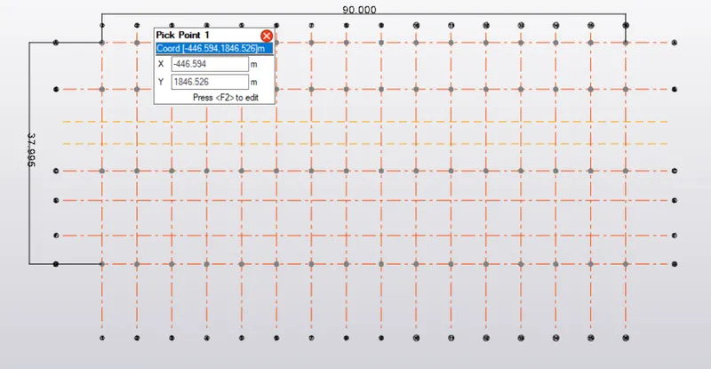
- Now go to the base level and start drawings grids accordingly.
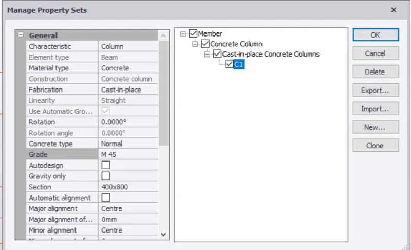
- Now go to the manage property tab and select the concret column with specific grade and dimensions.
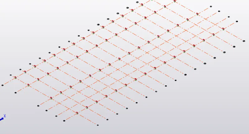
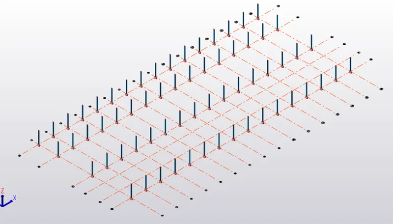
- Now add the steel column in the same way.
- Now select the beams option and select 2 different kind of beams to differentiate primary and secondery beams.
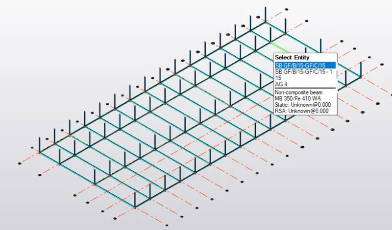
- Place them with at most care so that they do not overlap or concide.
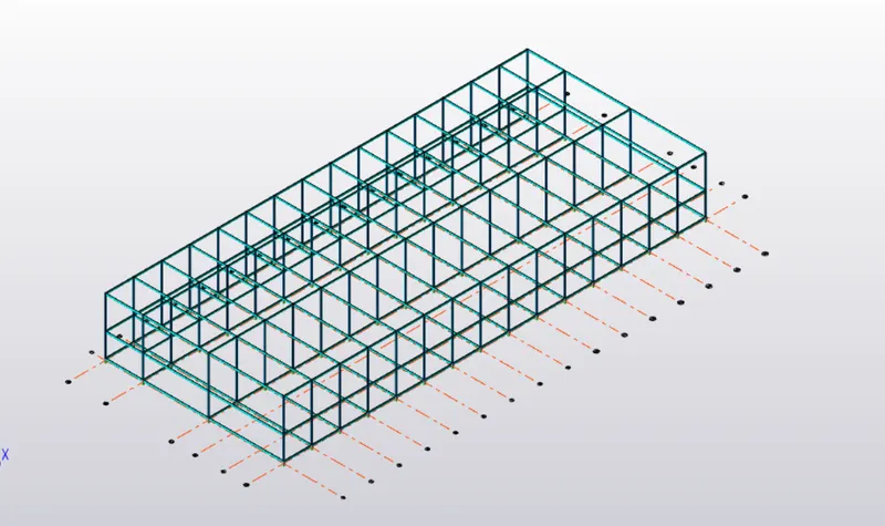
- Now place the construction grid line for the purpose of designing.
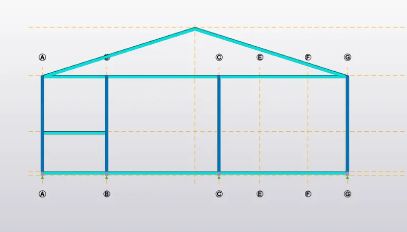
- Now select a particular frame of your choice and draw two construction lines so that we can create the roof for the structure.
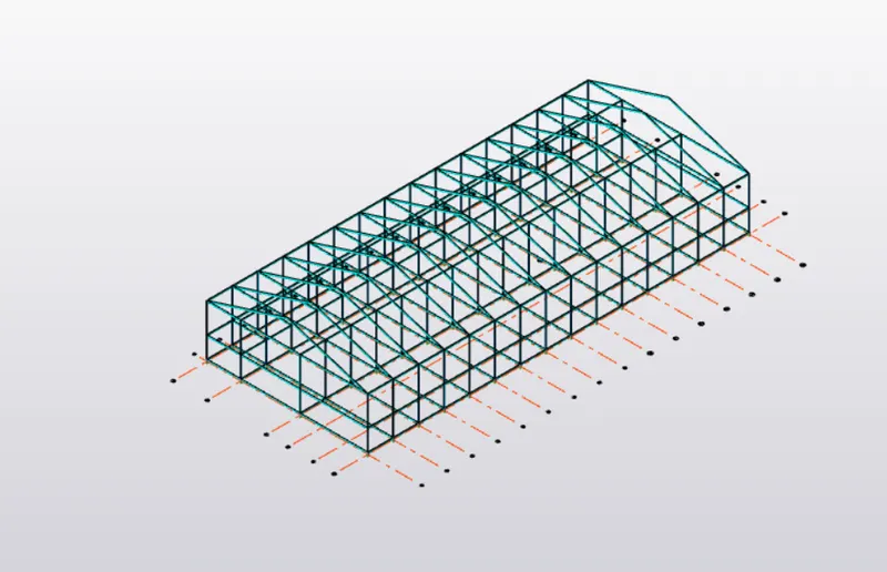
- Now go to the 3D structure and select the roof that is designed copy and paste it to the rest of the design.
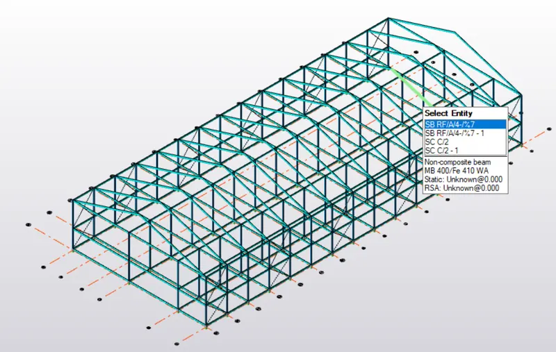
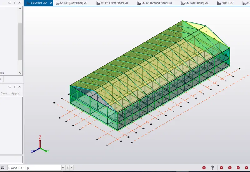
- Now we have to select the bracing option from the model tool and assign bracing for the model whereever required.
Result:
Here we are done with the columns, beams roof and bracings of the structure.
->Consider dead, live, equipment and wind loading. Consider the brick wall loading for 150mm thick and 1.5 KN per sq m for wall and roof cladding.
Ans)
Aim: To design the loads for the above designed structure.
Tools Required:
-> Slabs
->Load -> loadcases -> live dead and wind loads.
-> Wall Panels
-> Roof Panaes
-> Dimensions
-> Microsoft Excel Worksheet
-> Analysis
->Validate
Procedure:
- Now that we are done with the columns, beams roof and bracings of the structure.
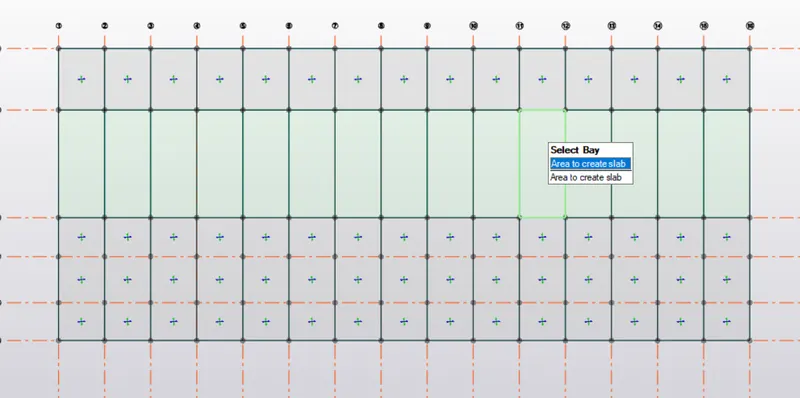
- Now with the help of slab icon draw the slab that is required for the structure that you can do it with the help of the dimenison icon where you can measure the lenght and width of the plot area.
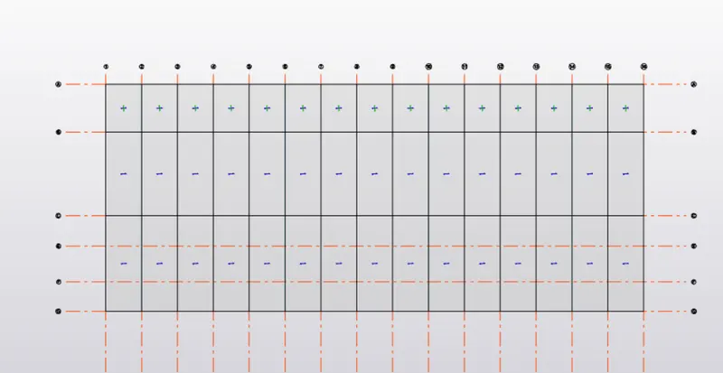
- Now according to that desin the One way salb or Two way slab.
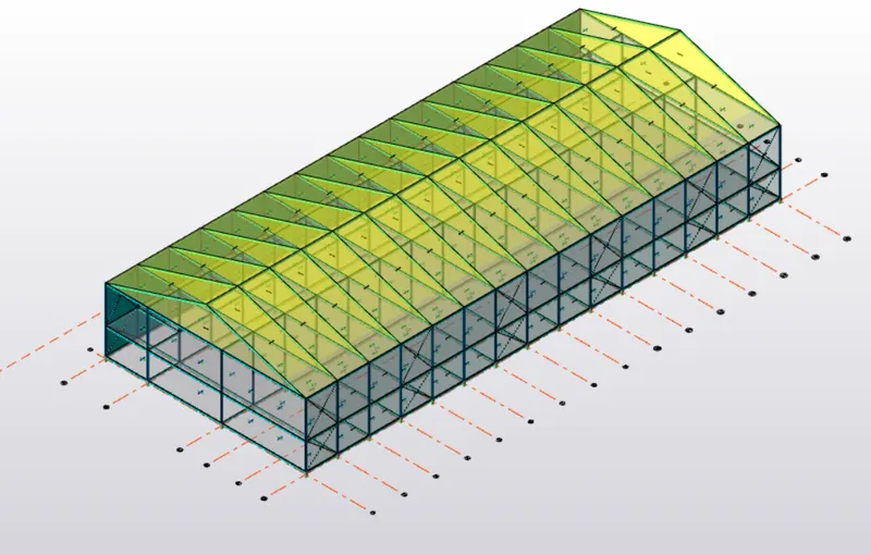
- Now select the wall panel option and assign wall panels to the structure.
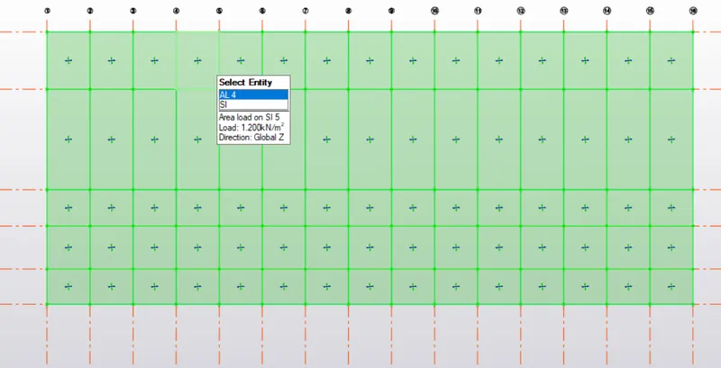
- Now select the roof panel option and assign the roof panel to the roof structure.
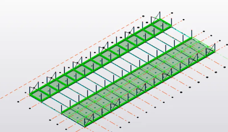
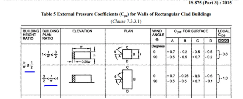
- Now calculate the Live, Dead and Wind loads for the structure according to the IS 875.
- After the calculation the loads are added to the model accordingly.
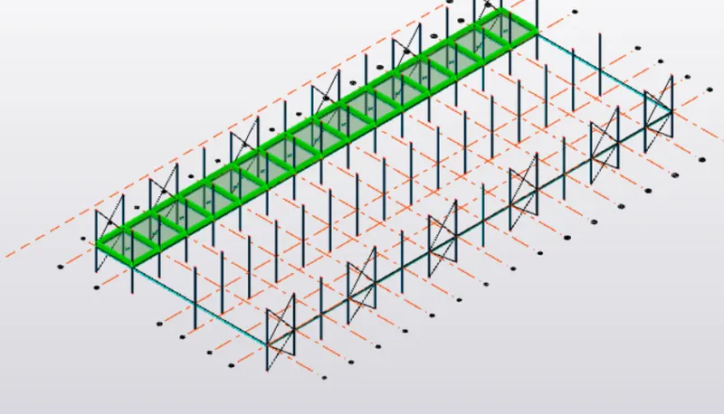
- Firstly the dead load is added.
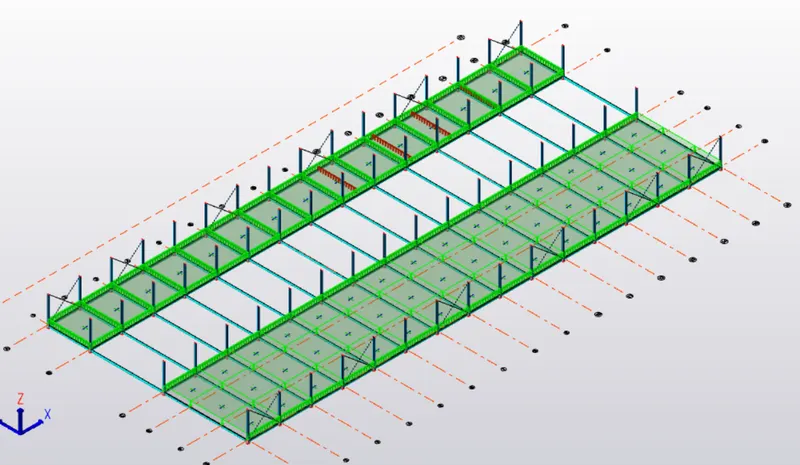
- Now at the bottom of our workspace we find dead load option in the drop up dialog box.
- Under load tab we have to select area and give the value of 1.2KN/m square, and select all the slabs.
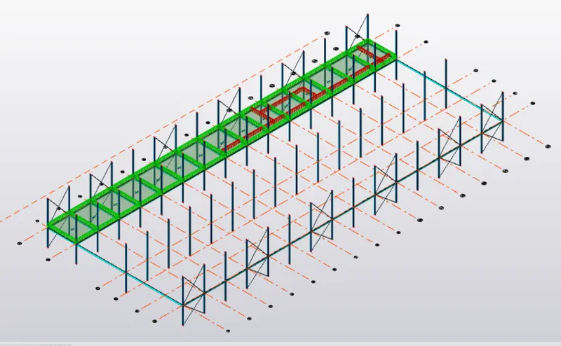
- Now select Line tool under load tab and draw the walls load in all the required floors.
Slab load = Model slab in software.
Finishes loading (50THK) = 0.05m x 24 KN/m^3 = 1.2 KN/m^2.
Brick wall with cement plaster thickness = 150mm => 0.155 * 20 KN\m => 3.1 KN\m^2.
Unit weight = 20 KN/m^3
Floor height (GF to FF) = 15.5 Kn\m
Brick wall loading = 15.5 KN/m
Floor height (FF to Roof) = 21.7KN\m
Brick wall loading = 15.5 KN/m
Roof loading = 1.5 KN/m^2
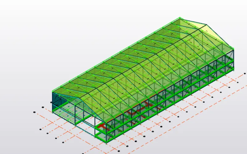
- Now add the live loads to the structure as per the calculation.
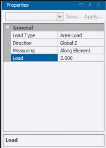
- Now at the bottom of our workspace we find Imposed load option in the drop up dialog box.
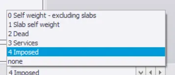
- Now we can provide live loads to the structure by selecting the load and assigning the value for it according to the IS Code.
- Click on loads icon and select area option under that.
- The live loads for the structure can be obtained from the IS building standard codes.
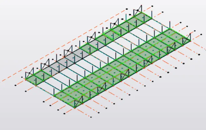
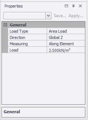
- Now under the property dialog box enter the required load for different room.
- Store room = 5 KN/m^2
Office = 3 KN/m^2
Rest room = 2 KN/m^2
Toilets = 2 KN/m^2
Pantry = 3 KN/m^2
Corridor = 4 KN/m^2
Meeting Room = 2KN\m^2
Maintainance Rom = 2.5KN\m
Equipment room = 10 KN/m^2
-
Now set the loads with different values and apply them by clicking on the respective slabs.
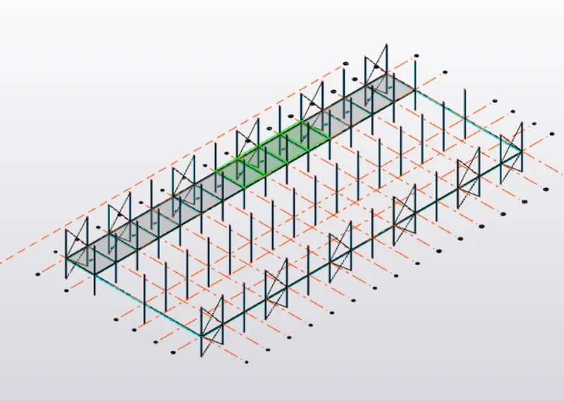
-
Now repeat the same process for all the remaining levels that is for the first and to top of the roof level.
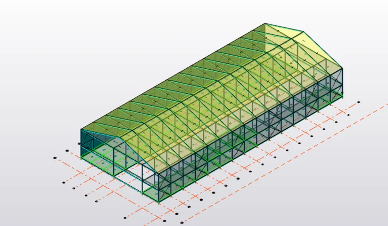
-
Do not forget to validate your model every now and then as to check your errors and correct them.
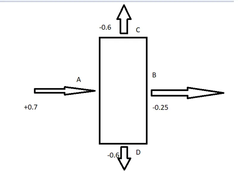
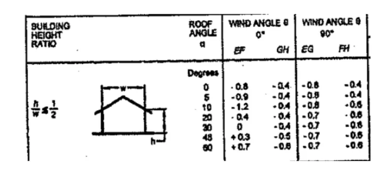
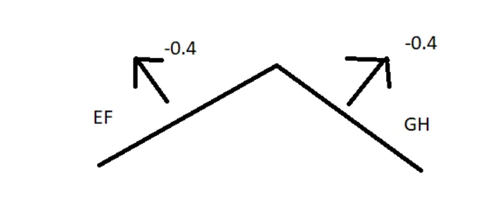
- Now we have to calculate the wind load as per the given requirement.
|
Wind load calculations as per IS: 875 P3-1987 |
||||||||||||
|
Basic parameters |
||||||||||||
|
Basic wind speed Vb= |
39 |
m/s |
Terrain category= |
2 |
||||||||
|
Probable design life= |
50 |
years |
class of structure = |
A |
||||||||
|
Greater horizontal dimension, l= |
90 |
m |
Ratio for wall and roof co-efficients: |
|||||||||
|
Lesser horizontal dimension, w= |
38 |
m |
||||||||||
|
Eaves level height = |
12 |
m |
wall = |
l/w = |
2.36 |
|||||||
|
Width of frame-1, grid A and B |
7 |
m |
h/w = |
0.31 |
||||||||
|
Roof = |
l/w = |
2.36 |
||||||||||
|
Topography factor, k1= |
1 |
|||||||||||
|
Risk co-efficient, k2= |
1.02 |
(for 50 years) |
||||||||||
|
Height(m)= |
upto 10 |
|||||||||||
|
Terrain factor & str.size factor k3= |
1 |
|||||||||||
|
Important factor for cyclonic, k4= |
1.15 |
|||||||||||
|
Design wind speed , Vz= Vb*k1*k2*k3*k4= |
45.747 |
|||||||||||
|
Design wind pressure (N/m) |
(N/m^2), Pz= 0.6*vz^2= |
1207.1 |
||||||||||
|
Design wind speed(kN/m^2), Pz = |
1.207 |
|||||||||||
|
Roof angle, α = |
16 |
degree |
||||||||||
|
Internal pressure coefficient, α = |
0.5 |
(upto 20% opening) () |
(Cl.6.2.3.3 IS 875 P3:1987) |
|||||||||
|
Internal pressure coefficient, α = |
-0.5 |
(upto 20% opening) () |
||||||||||
|
Wall loading calculations : |
||||||||||||
|
Wind direction : +Y |
||||||||||||
|
Wind load along Y-Direction |
(Face A): |
_+ Cpi |
_- Cpi |
|||||||||
|
Height at different level = |
upto 10 |
upto 10 |
||||||||||
|
External pressure coefficient, Cpe = |
0.7 |
0.7 |
||||||||||
|
Internal pressure coefficient, Cpi = |
0.7 |
-0.7 |
||||||||||
|
Net pressure coefficient, Cp = |
0 |
1.4 |
||||||||||
|
Design wind pressure for wall = |
1.25 |
1.25 |
||||||||||
|
Loading to be applied on the wall = |
0 |
1.75 |
||||||||||
|
factor ( loading * 1.05) = |
0 |
1.837 |
||||||||||
|
Wind load along Y-Direction |
(face B): |
_+Cpi |
_-Cpi |
|||||||||
|
Height at different level = |
upto 10 |
upto 10 |
||||||||||
|
External pressure coefficient, Cpe = |
-0.25 |
-0.25 |
||||||||||
|
Internal pressure coefficient, Cpi = |
0.7 |
-0.7 |
||||||||||
|
Net pressure coefficient, Cp = |
-0.95 |
0.45 |
||||||||||
|
Design wind pressure for wall = |
1.25 |
1.25 |
||||||||||
|
Loading to be applied on the wall = |
-1.187 |
0.562 |
||||||||||
|
factor ( loading * 1.05) = |
-1.24 |
0.590 |
||||||||||
|
Wind load along Y-Direction |
(Face C & D) |
_+Cpi |
_-Cpi |
|||||||||
|
Height at different level = |
upto 10 |
upto 10 |
||||||||||
|
External pressure coefficient, Cpe = |
-0.6 |
-0.6 |
||||||||||
|
Internal pressure coefficient, Cpi = |
0.7 |
-0.7 |
||||||||||
|
Net pressure coefficient, Cp = |
-1.3 |
-0.1 |
||||||||||
|
Design wind pressure for wall = |
1.25 |
1.25 |
||||||||||
|
Loading to be applied on the wall = |
-1.625 |
0.125 |
||||||||||
|
factor ( loading * 1.05) = |
-1.706 |
-0.131 |
||||||||||
|
Roof loading calculations |
||||||||||||
|
Wind direction -Y |
_+Cpi |
_-Cpi |
||||||||||
|
h/w = 0.31 |
h/w = 0.31 |
|||||||||||
|
External pressure coefficient, Cpe = |
-0.88 |
-0.4 |
-0.88 |
-0.4 |
||||||||
|
Internal pressure coefficient, Cpi = |
0.5 |
0.5 |
-0.5 |
-0.5 |
||||||||
|
Net pressure coefficient, Cp = |
-1.38 |
-0.9 |
-0.38 |
0.1 |
||||||||
|
Design wind pressure for roof, Pz = |
1.207 |
1.207 |
1.207 |
1.207 |
||||||||
|
Wind load along X-direction ( Roof EG): |
_+Cpi |
_-Cpi |
||||||||||
|
Height at different level = |
upto 10 |
upto 10 |
||||||||||
|
External pressure coefficient, Cpe = |
-0.4 |
-0.4 |
||||||||||
|
Internal pressure coefficient, Cpi = |
0.7 |
-0.7 |
||||||||||
|
Net pressure coefficient, Cp = |
-1.1 |
-0.3 |
||||||||||
|
Design wind pressure for wall = |
1.25 |
1.25 |
||||||||||
|
Loading to be applied on the wall = |
-1.375 |
0.375 |
||||||||||
|
factor ( loading * 1.05) = |
-1.443 |
0.393 |
||||||||||
|
Wind load along X- direction ( Roof FH) : |
_+Cpi |
_-Cpi |
||||||||||
|
Height at different level = |
upto 10 |
upto 10 |
||||||||||
|
External pressure coefficient, Cpe = |
-0.4 |
-0.4 |
||||||||||
|
Internal pressure coefficient, Cpi = |
0.7 |
-0.7 |
||||||||||
|
Net pressure coefficient, Cp = |
-1.1 |
0.3 |
||||||||||
|
Design wind pressure for wall = |
1.25 |
1.25 |
||||||||||
|
Loading to be applied on the wall = |
-1.375 |
0.375 |
||||||||||
|
factor ( loading * 1.05) = |
-1.443 |
0.393 |
||||||||||
- Now in the below bar of the workspace assign a particular load to the frames that are to be assigned.
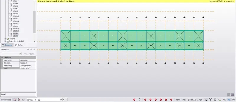
- Repeat the loads for the Faces of A,B,C and D accordingly.
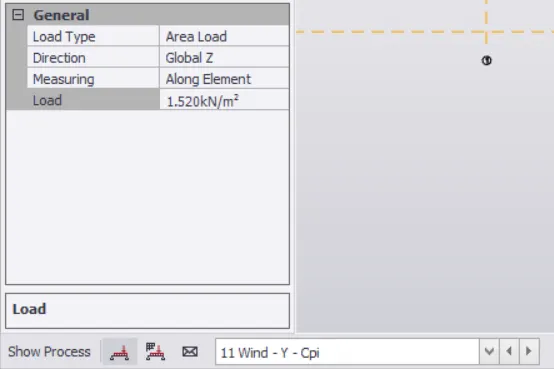
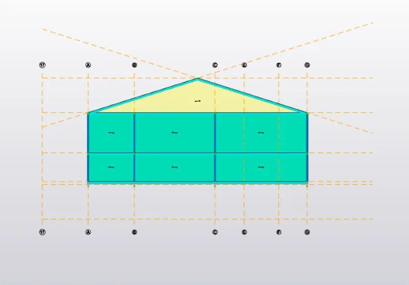
- Assign the load to the roof also.
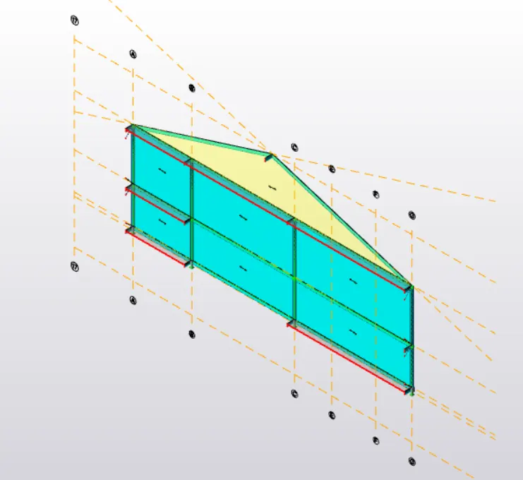
- Now the application of wind load is done to the model accordingly.
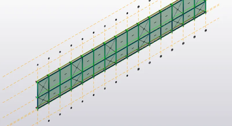
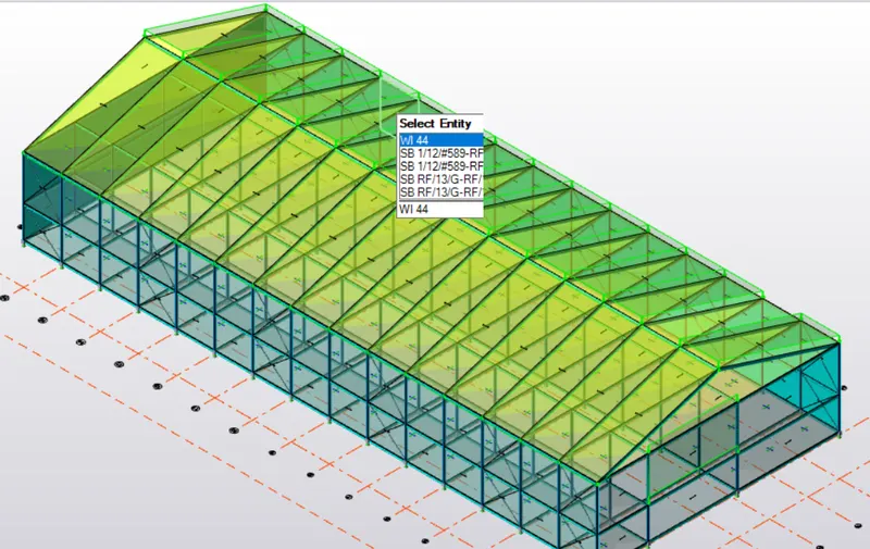
- Now Crane load Calculations are to be done.
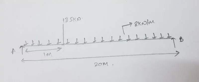
Crane Load Calculation:
Max wheel load
Maximum concentrated load on crane = 100 + 35 = 135KN.
Self-weight of crane will act as uniformly distributed load of intensity
= 160/20 = 8 KN/m.
Taking moment about B:
Ra x 20 – (135) x (19-8) x (20 x 10) = 0
20 Ra = 297000
Ra = 208.25 KN.
Taking moment about A:
Rb x 20 – (135) x (1 - 8)(20 x 10) = 0
20 Rb = 189000
Rb = 86.75KN.
Ra + Rb = 100 KN.
The reaction from the crane girder is distributed equally on two wheels at the end of the crane girder.
Maximum wheel load on each of the crane wheel = 208.25 / 2 = 104.125KN.
MAXIMUM BENDING MOMENT :
Assume self-weight of the gantry girder as 1.5 KN/m
Total dead load = ( Self-weight of rail + self-weight of gantry girder ) 0.3 + 1.5 = 1.8KN/m
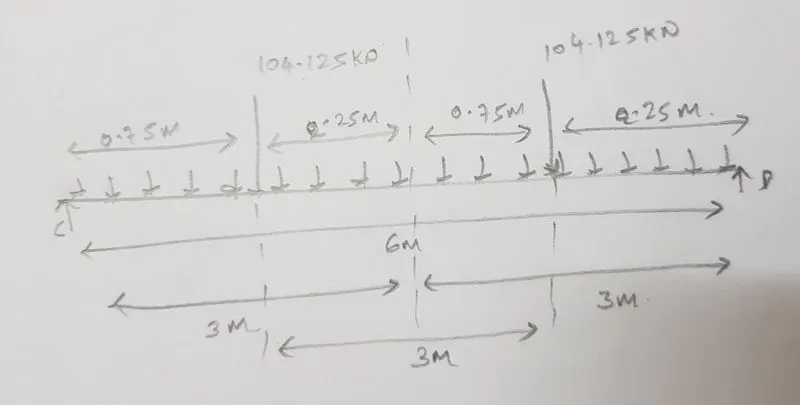
Taking moment about D:
Rc x 6 - 104.125 x (20.25 + 3) -104.125 x 2.25= 0
6 Rc = 2655.187
Rc = 24655.187 / 6
Rc = 130.15 KN.
Taking moment about C:
Rd x 6 - 104.125 x (0.75 + 3) -104.125 x 0.75= 0
Rd x 6 = 468.56
Rd = 468.56 / 6
Rd = 78.09 KN.
Bending moment under wheel due to live load = Rd x 2
= 78.09 x 2
= 156.18 KNm.
Bending moment due to impact = 0.10 x 156.18 ( 10 % increase due to MOT)
= 15.618KNm
Total bending moment due to live load and impact load = 156.18+ 15.618
= 171.798 KNm.
Bending moment due to dead load = W x l x l / 2
= 1.8 x 6 x 6/ 2 = 8.1 KNm
Maximum bending moment = 171.798+ 8.1
= 179.89 KNm.
MAXIMUM SHEAR FORCE :
For maximum shear force, one of
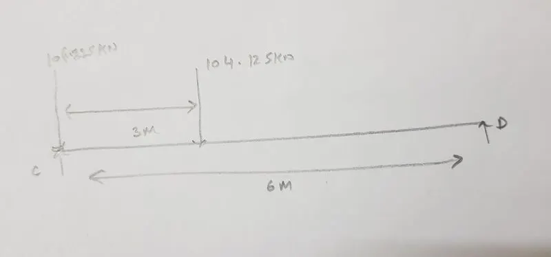
Rc x 6 – 104.125 x 6 -104.125 x 3 = 0
Rc = 937.125 / 6
Rc = 156.18 KN
The maximum shear force due to wheel load = 156.18 KN
LATERAL FORCES :
Lateral forces traverse to rails = 5% of the weight of crab and weight lifted
= 0.05 ( 135 )
= 6.75KN
Lateral forces on each side wheel F1 = 6.75/ 2 = 3.375 KN
Maximum horizontal reaction due to the lateral force by proportion at C
= Lateral force x reaction at C due to vertical load / maximum wheel load due to vertical load
= 3.375 x (130.15 / 104.125) = 4.21 KN
At D
= Lateral force x reaction at D due to vertical load / maximum wheel load due to vertical load
= 3.375 x (78.09 / 104.125) = 2.53 KN
4.21 + 2.54 = 6.74 KN
Bending moment due to lateral load by proportion
= 3.375 x (15.18 \ 104.125)
= 5.06 KNm.
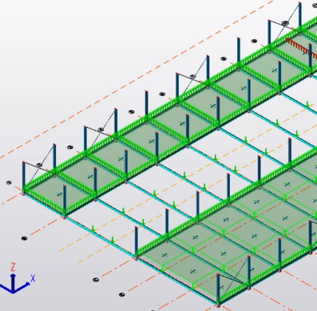
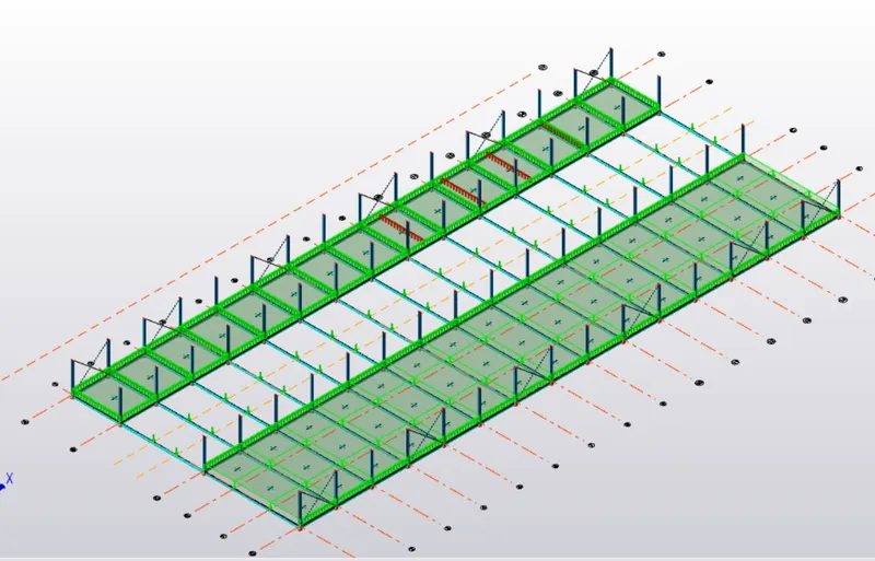
- Now these loads are added to the structure as point loads.
Analysis of the structure:
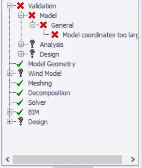
- Now that all the loads are applied we can now do the fisrt order analysis and then validate the structure to see and errors.
- If any errors found they would be listed under the validate option and when we click on the error we will be directed to that error place and it is highlighted with a solid arrow.
- Correct the error by changing the size of the particular beam or column.
- Now select the analyse option on the top task bar, under that we have to click the 1st order liner option.
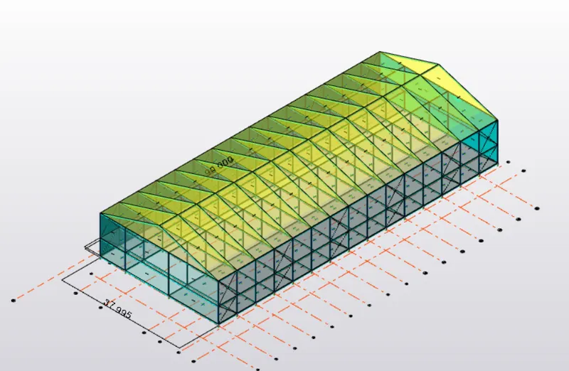
- Now the analysis is done and will show us the errors once it is done.
- Now click on the particular member and when we do the left click on it we get a dialogue box under that select the check member option and under that select the static option which displays another dialogue box.
- Now in the new dialogue box we can find the load analysis manually done and there we can check the value that is obtained of the loads that we have give or the material that we have chosen.
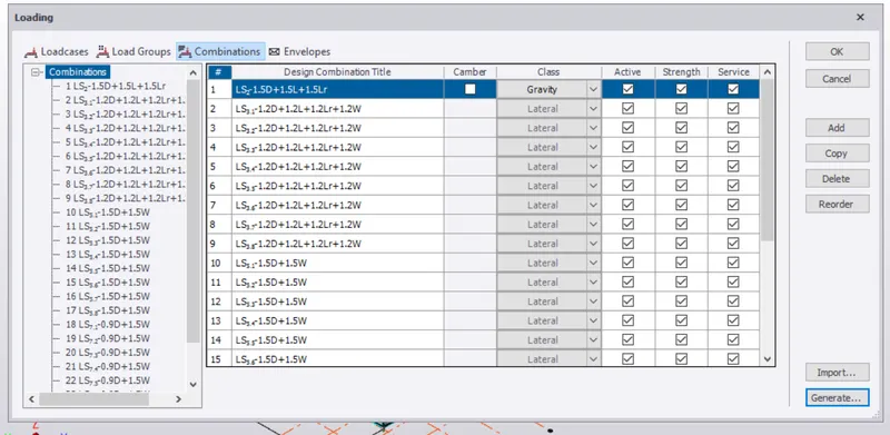
- Now check the values that we obtained by manual calculations and check the actual value that has to come out with the help of IS Code book.
- Now change the size of the structural members accordingly.
Result:
Hence Analysis of the structure is done with the help of proper designing.