Project 1
Consider dead, live, equipment and wind loading. Consider the brick wall loading for 150mm thick and 1.5 KN per sq m for wall and roof cladding.
Assume wind loading basic speed as 39m/s
Aim:
To create a dead, live and wind loading and apply it in tekla model.
Procedure:
Step 1:
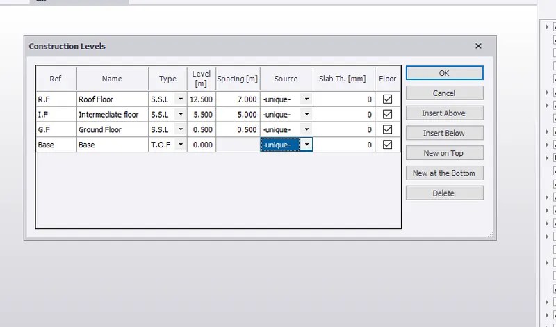
1) Go to Model tab and select Construction level
2) Edit the construction level from Base to Roof
3) Click ok
Step 2:
1) Go to Model tab
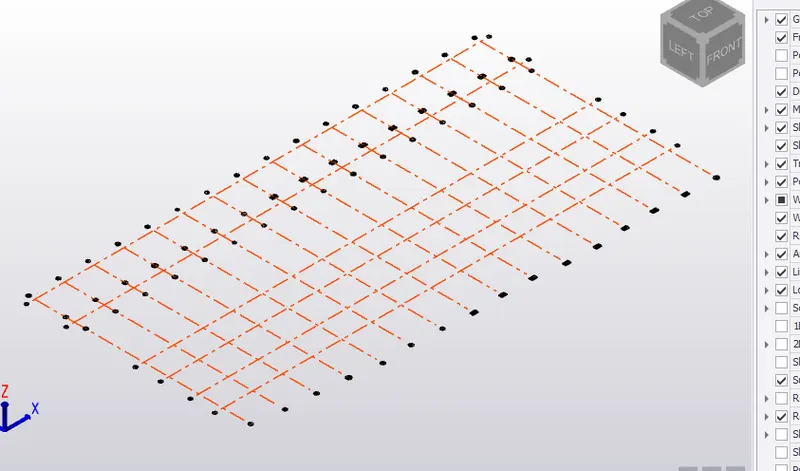
2) Select construction line under the grid option
3) Draw the grid as per the drawing provided in the question
4) Click ok
Step 3:
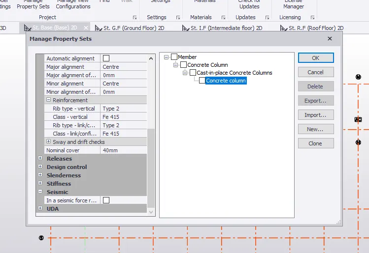
1) Go to Manage property set
2) click new and add the concrete column
3) Edit the column size as 400x800 and grade as M45
4) Clik ok
Step 4:
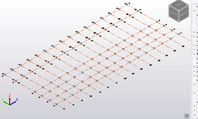
1) Go to model tab and select concrete column
2) Select Concrete column from property window
3) Place the column in all the grid point from base to ground floor
4) Press ESC to exit the editing
Step 5:
1) Go to Manage property set
2) click new and add the Steel column
3) Edit the beam size as ISMB 450 universal column
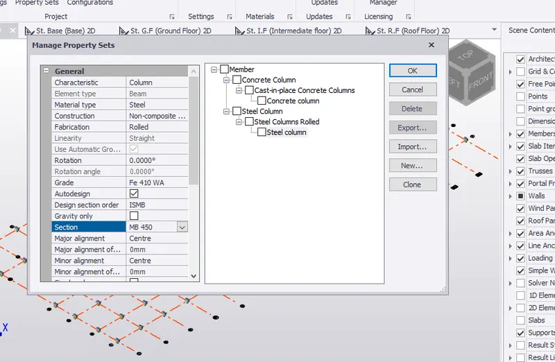
Step 6:
1) Go to model tab and select steel column
2) Select Steel from property window
3) Place the column in all the grid point
4) Press ESC to exit the editing
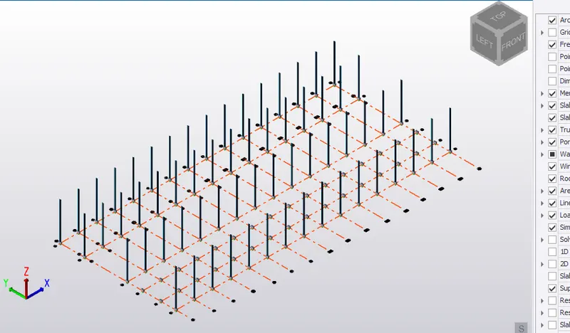
Step 7:
1) To create a new beam member, go to the home tab and choose to manage property sets
2) Click new and select steel beam
3) Set the beam section as MB 500 and rename this beam as Steel beam
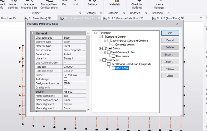
Step 8:
1) Place the Steel beam in grid 1
2) switch it into 3d view
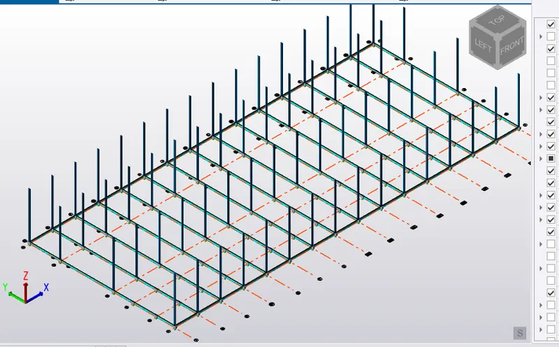
Step 9:
Similarly do the same procedure for first floor and roof floor also
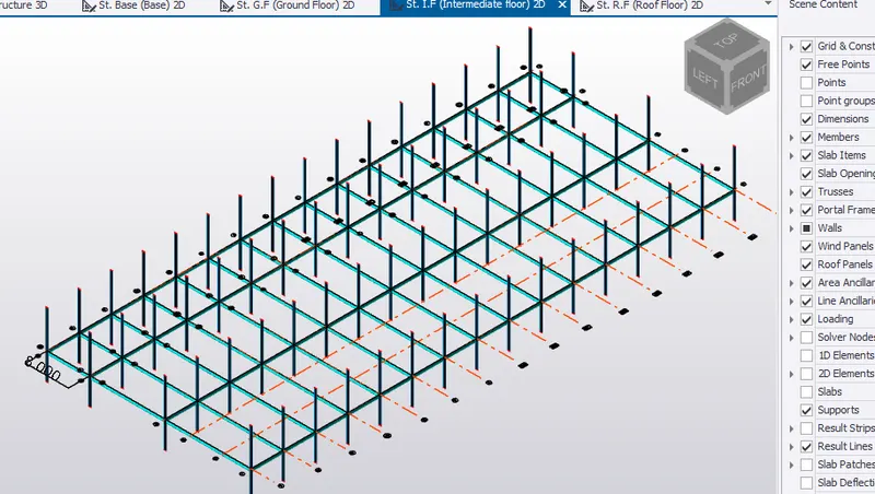
First floor
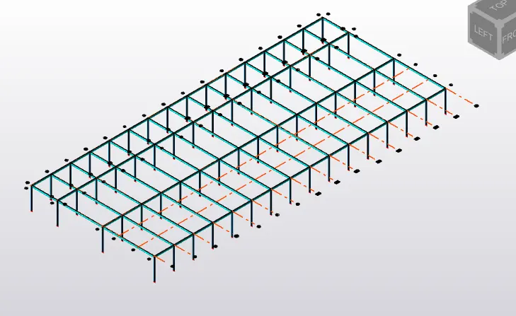
Roof Floor
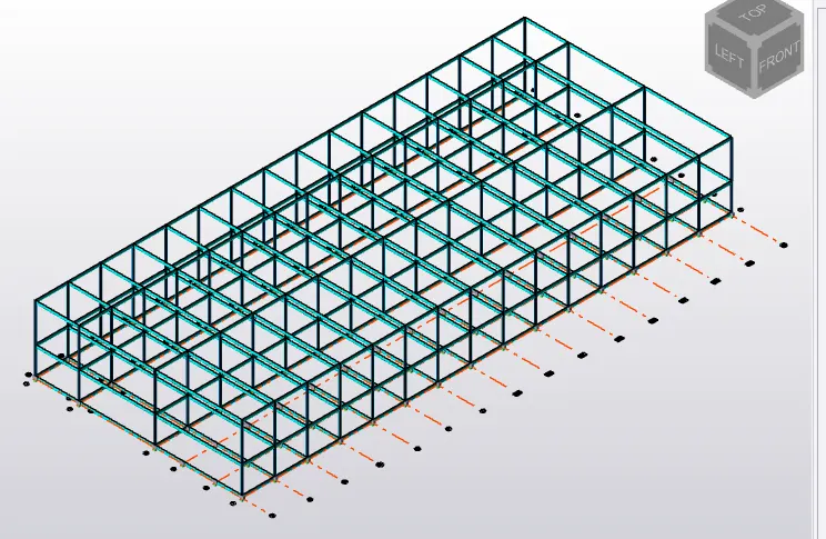
Full Structure:
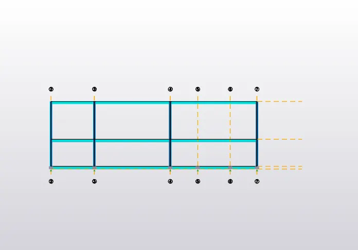
Step 10:
Frame:
1) click Model tab
2) Select frame option and choose the first frame
3) Under the structure tab click first tab
Step 11:
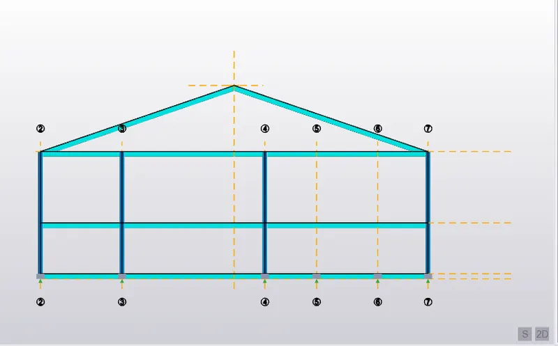
1) Divide the frame half of it and measure it
2) draw the construction line at the height of 6m
3) Click the beam and draw the rafter beam using the construction line
Step 12:
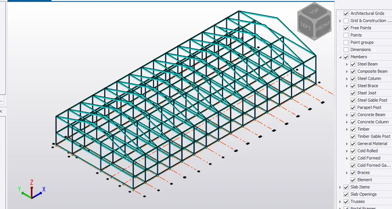
1) Copy the frame for all the grids
Step 13:
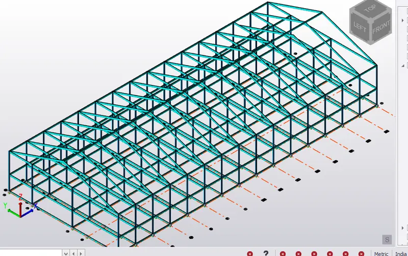
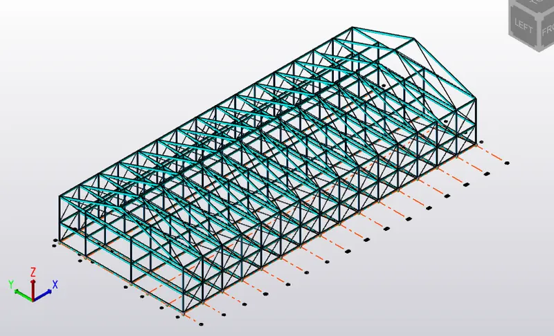
Add the rafter beam in roof
Step 14:
Bracings:
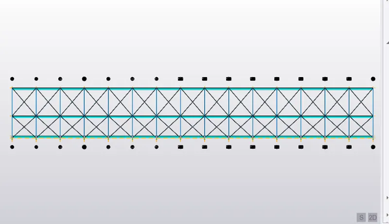
1) Click the frame and selct the A grid
2) Click Bracing and choose X bracing
3) Draw the bracing into the model
Step 15:
Apply the bracings in Roof also
Step 16:
Slab Properties:
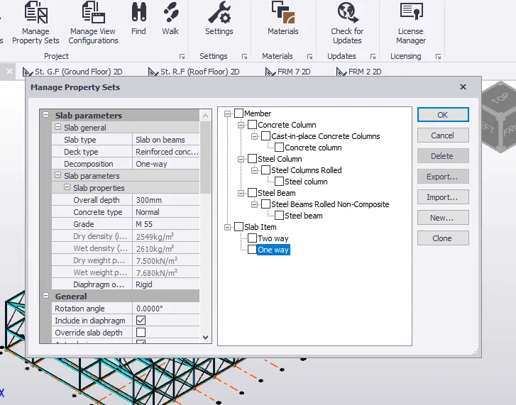
1) Go to Manage property set
2) click new and add the cast insitu slab
3) Edit the slab as M55 and overall depth as 300mm
4) Clik ok
Step 17:
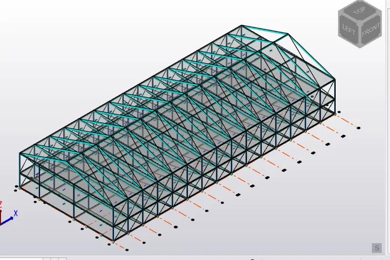
1) Apply the slab properties in ground floor, first floor and roof
Step 18:
Load Calculation:
Dead Load:
As per IS 875 Part 1
1) Slab load = (As provided by software in the model)
2) Finishing load (50mm) = 0.05m x 24 Kn/m^2 = 1.2 kN m^2
3) Brickwall loading = 150mm thickness
4) Unit weight = 20 kn/m^3
5) Floor height (G.F to F.F) = 5 m
Brickwall loading = 150 x 20 x 5/1000
= 15 Kn/m
7) Floor height (F.F to Roof) = 7 m
Brickwall loading = 150 x 20 x 7/1000
= 21 kn/m
8) Roof loading = 1.2 kN/m
Step 19:
Applying Load on Model:
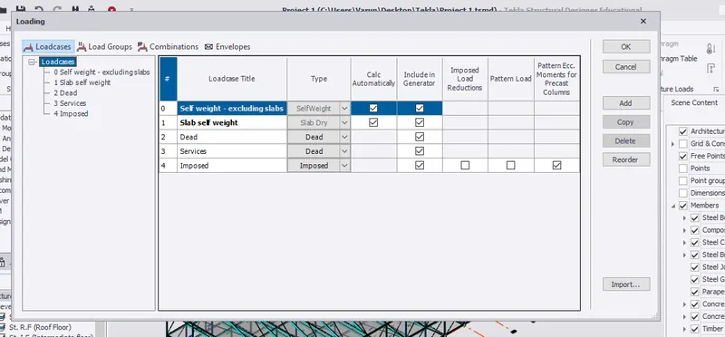
1) Click the Load tab in the ribbon panel
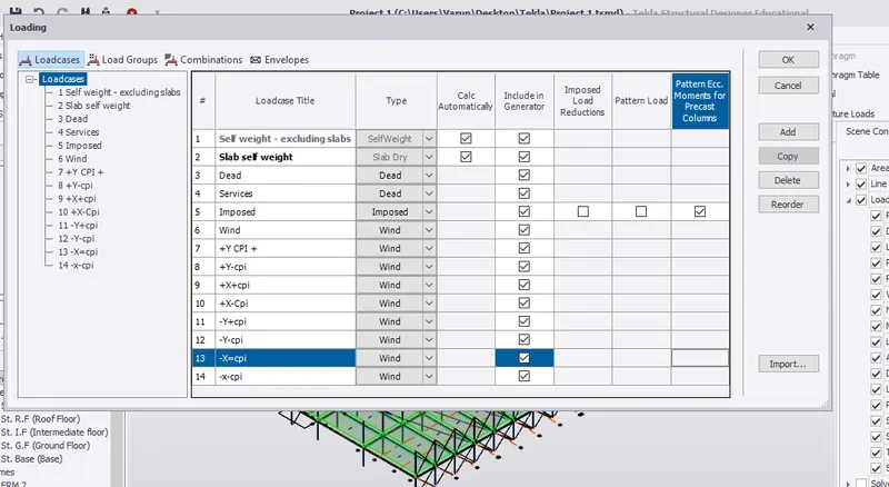
2) Select Load cases and add the new loads such as Wind, Crane, and Seismic
3) Choose the type of the load as per load case titles.
4) Click ok
Step 20:
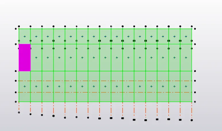
Applying Dead loads on Ground floor:
1) Click the drop down list from the bottom tool bar
2) Choose Dead load from the list
3) Select the Area loading option from the ribbon tab
4) Change the load value under the property panel to 1.2 kn/m
Step 21:
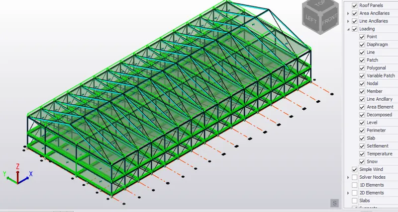
Similarly apply the loadings in all the floors
Step 22:
Live load Calculation:
As per IS 875 part 2, table 1:
Toilet = 2 kN
Staircase = 5 kN
Store room = 5 kN
Equipment room = 10 kN
Conference room = 5 kN
Canteen = 3 kN
Maintanence room = 2.5 kN
Office room = 5kN
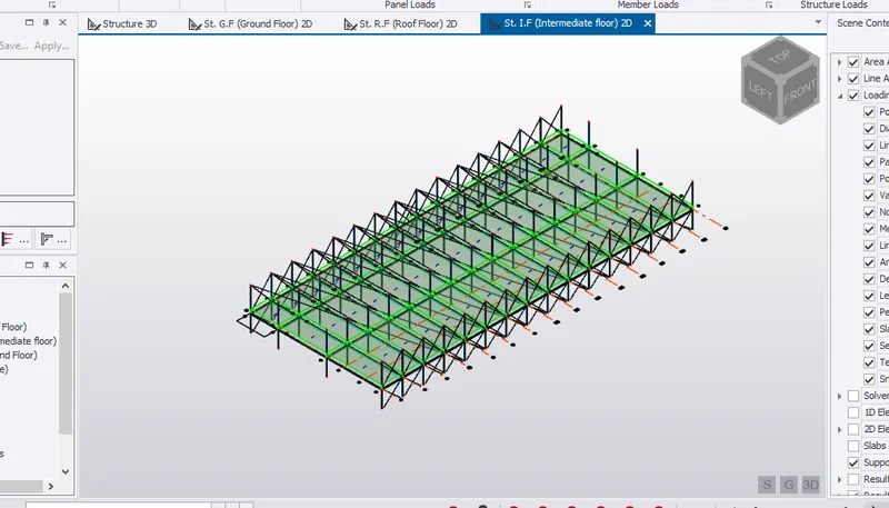
1) Apply live load ground and first floor.
2) Live loads taken from IS 875 part 2, Table 1
3) Change the load type as Imposed and select area load
4) Then place the loadng at suitable rooms
Wind Load:
Step 23:
1) Basic Wind speed = 39 ( From Appendix A- Clause 5.2)
2) Life of Structure = 50 years ( Table 1 Clause 5.9.1)
3) Class of Structure = Class A
As per IS 875 Part 3- Clause 5.3.2.2, Structures and/or their components such as cladding, glazing, roofing, etc, having maximum dimension ( greatest horizontal or
vertical dimension ) less than 20 m which is considered as Class A.
4) Terrain Category = 2 ( From Table 2)
5) Total length of the building (l) = 90 m
6) Total Height of the building (h) = 12 m
7) Total Width of the building (w) = 38m
8) Therefore, L/W = 2.36 and h/w = 0.31
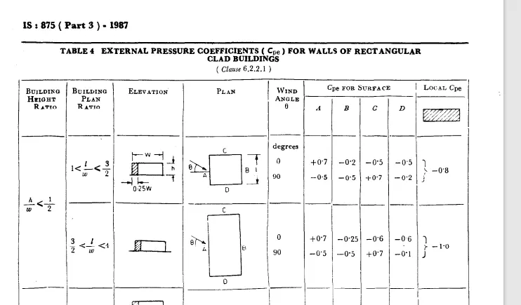
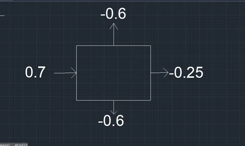
Since h/w is less than 0.5 & l/w is > 1.5, we need to take the 3/2<l/w<1 from the table 4 of IS 875 part 3: 1987
Step 24:
External Pressure Coefficent (Cpe)
Step 25:
Finding the Factors (k1, k2, k3, k4)
k1:
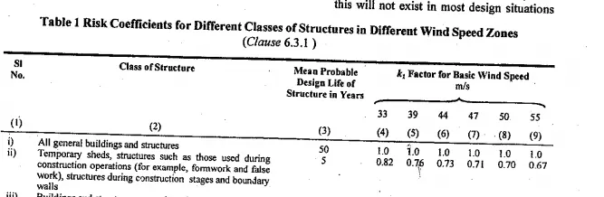
From Table 1 for the basic wind speed for 39 m/s,
Risk Coeffiecent, K1 = 1.0
2:
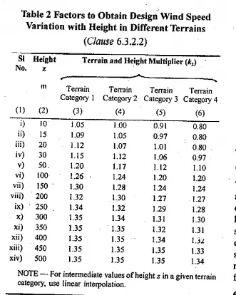
From Table 2,
10m height = 1 for terrain category 2
15m height = 1.05
by using the interpolation method,
k2 = 1.02
K3:
Topography factor , k3 = 1 (from clause 6.3.3)
K4:
Importance factor K4 = 1.15 (from Clause 6.3.4)
Design Wind speed:
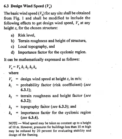
Vz = Vb x k1 x k2 x k3 x k4
= 39x1x1.02x1x1.15
= 45.747 m/s
Design wind pressure:
From Clause 7.2
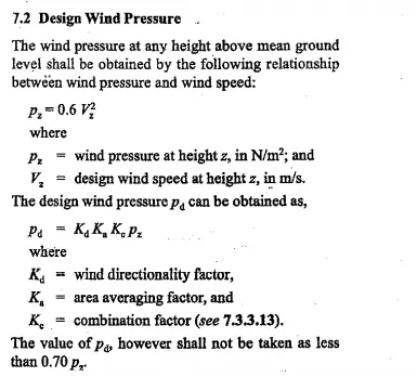
Pz = 0.6 Vz^2
= 0.6 x 45.747^2
= 1255.6728 n/sq.m
= 1.2556 kn/sq.m
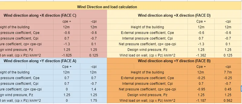
Step 26:
Roof Calculation:
W.k.t
h/w = 0.31
In order external coefficient from the table 6

Slope =18 deg

Step 27:
Apply the wind load in Tekla model:
1) Open load tab
2) Select load case and add the required wind loads
3) Click ok
2) Analyze and design a steel building to 10T CRANE as per IS standard code in TEKLA STRUCTURAL DESIGNER.
Aim:
To design and analyze a steel building to 10T CRANE as per IS standard code in TEKLA STRUCTURAL DESIGNER.
Procedure:
Crane Load Calculations:
Given Data:
Crane capacity = 100 KN
Weight of the crab = 35 KN
Weight of the crane = 160 KN
Maximum hook approach =1m
Wheel base =3m
Distance between c/c gantry rails = 20.0 m
Distance between c/c gantry column =6 m
Crane type = Gantry crane
Maximum wheel load:
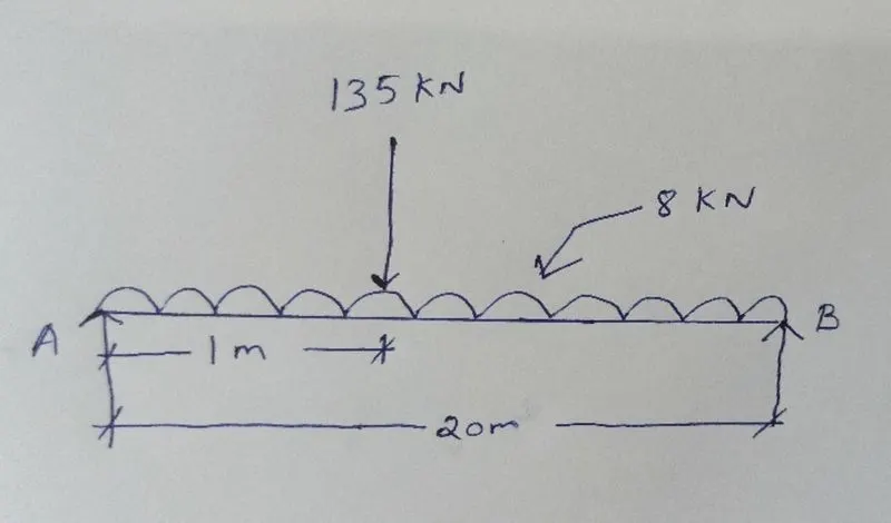
Maximum point load on the crane = crane capacity + weight of the crab = 100 + 35 = 135KN
Self-weight of the crane = 160 KN
= 160 /20 = 8 KN
Taking Moment about B
RA X 20 -135 X 19 -8 X 20 X 10 =0
RA= 208.25 KN
Taking Moment about A
RBX 20 -135 X 1 -8 x 20 x 10 =0
RB = 86.75 KN
Maximum wheel load on each wheel = RA / 2 = 208.25 /2
= 104 .125 KN
Maximum Bending Moment :
Assume self-weight of gantry girder as 1.5 KN/m
Assume self-weight of rail as 0.3 KN/m
Total dead load = 0.3 + 1.5 = 1.8 KN/m
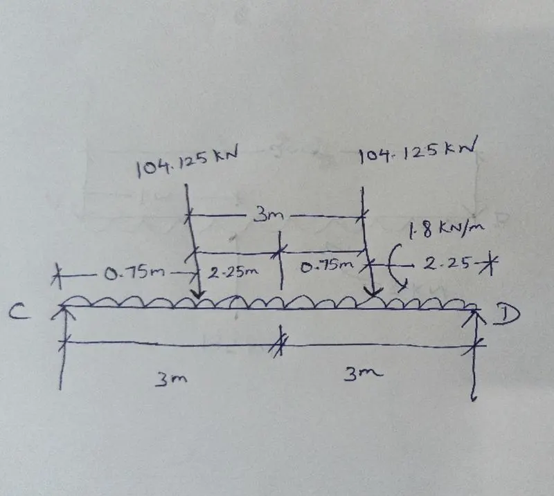
At D
RCx 6 -104.125 x ( 2.25 + 3) -104.125 X 2.25 =0
Rc = 130.15 KN
At C
RDX 6 -104 .125 ( 0.75 +3 ) -104.125 X 0.75 =0
RD= 78.09 KN
RC + RD = 208.25 KN
Bending Moment under a wheel load due to live load
= 78.09 X 2
= 156.18 KNm
Bending moment due to impact =0.10 X 156.18 ( 10 % due to M.O.T)
= 15.618 KN m
Total bending moment due to live load and impact load = 171.79 KN m
Bending moment due to dead load Wl2/8=1.8 X 6x6 /8 = 8.1 KNm
Maximum bending moment = 171.79 + 8.1 = 179.89 KN m
Maximum shear force :
At D
Rc x 6 -104.125 x 6 -104.125 x3 =0
Rc= 156.18 KN
Hence the Maximum shear force due to wheel load is 156 .18 KN
Lateral Forces :
Lateral force transverse to rails = 5 % of the weight of crab and weight lifted
= 0.05 x 135
= 6.75 KN
Lateral forces on each wheel = 3.375 KN
Maximum horizontal reaction due to lateral force by proportion at C
= lateral force x reaction at c due to vertical load / Maximum wheel load due to vertical load
= 3.375 X 130.15 / 104.125
= 4.21 KN
Horizontal reaction due to lateral force by proportion at D
= lateral force x reaction at D due to vertical load / Maximum wheel load due to vertical load
= 3.375 x 78.09 / 104.125
= 2.53 KN
4.21 + 2.54 = 6.74 KN
Bending moment due to lateral load = 3.375 X 15.18 / 104.125 = 5.06 KNm