Planetary Gear
PLANETARY GEAR DESIGN AND MOTION ANALYSIS IN SOLIDWORKS
AIM
The aim of this project is to design the 3D model of planetary gear system with proper dimensions. Pitch circle diameter is one of the main features in transmission gear system. So, using given module and number of teeth find out the pitch circle diameter of planet gear. Finally, study about motion analysis of planetary gear and get some plots for angular velocities in three different conditions.
INTRODUCTION
Epicyclic gearing or planetary gearing is a gear system consisting of one or more planet or pinion gears, revolving about a central sun gear or sun wheel. Typically, the planet gears are mounted on a movable arm or carrier, which itself may rotate relative to the sun gear. Epicyclic gearing systems also incorporate the use of an outer ring gear or annulus, which meshes with the planet gears. The modules for all gears are same and calculate the number of teeth and pitch circle diameter for planet gear using given module and number of teeth for sun gear and ring gear. 2D sketch of all the part design is the basic and initial step to proceed the further process.
Planetary gears or epicyclic gears are typically classified as simple or compound planetary gears. Simple planetary gears have one sun, one ring, one carrier, and one planet set. Compound planetary gears involve one or more of the following three types of structures: meshed-planet, stepped-planet, and multi-stage structures. Compared to simple planetary gears, compound planetary gears have the advantages of larger reduction ratio, higher torque-to-weight ratio, and more flexible configurations. Here is the simple planetary gear system used for motion study. Finally, the input speed of 200rpm given to all the gears at every stages individually and find out the angular velocity of output gear by fixing the one gear at every stage.
The angular velocity is the rate at which displacement is changing with respect to the time in circular motion. In the simplest case of circular motion at radius r, with position given by the angular displacement ϕ(t) from the x-axis, the orbital angular velocity is the rate of change of angle with respect to time:
⸫ ω=dϕ/dt
THEORY
You can use motion analysis to accurately simulate and analyse the motion of an assembly while incorporating the effects of motion study elements (including forces, springs, dampers, and friction). A motion analysis study combines motion study elements with mates in motion calculations. Consequently, motion constraints, material properties, mass, and component contact are included in the solidworks motion kinematic solver calculations. A motion analysis study also calculates loads that can be used to define load cases for structural analyses. To use the solidworks motion solver in a motion study, select motion analysis from the motion studies type list in the motion manager.
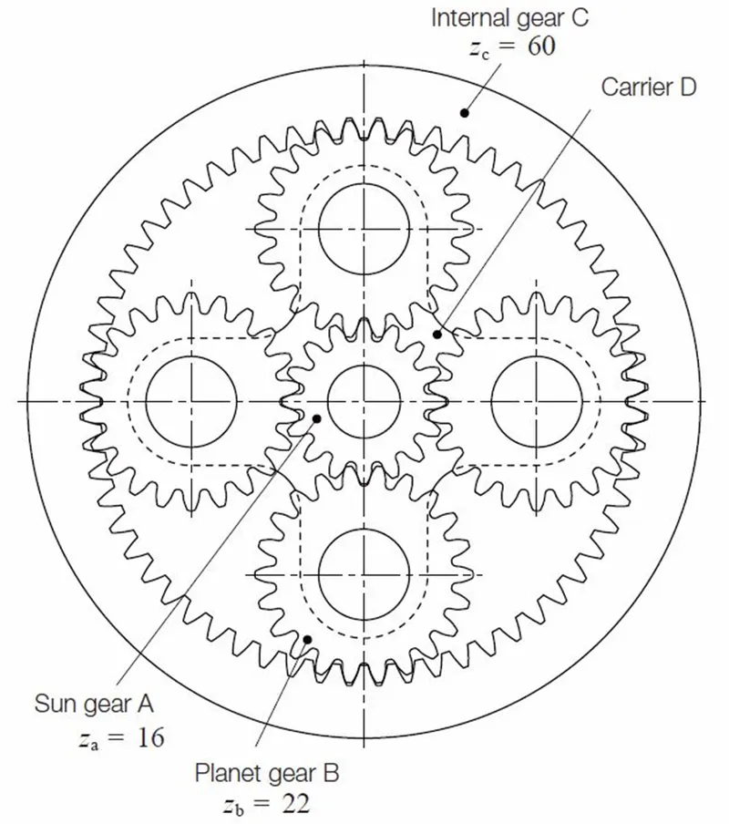
The gear ratio of an epicyclic gearing system is somewhat non-intuitive, particularly because there are several ways in which an input rotation can be converted into an output rotation. The three basic components of the epicyclic gear are:
- Sun: The central gear
- Carrier: Holds one or more peripheral Planet gears, all of the same size, meshed with the sun gear
- Ring or Annulus: An outer ring with inward-facing teeth that mesh with the planet gear or gears
The overall gear ratio of a simple planetary gearset can be calculated using the following two equations, representing the sun-planet and planet-ring interactions respectively:
Nsωs+Npωp-(Ns+Np) ωc=0
Nrωr-Npωp-(Nr-Np) ωc=0
Where,
ωs, ωp, ωr, ωc is the angular velocity of the ring gear, sun gear, planet gears and planet Carrier respectively
Nr, Ns, Np is the Number of teeth of the ring gear, Sun gear and each Planet gear respectively.
from which we can derive the following:
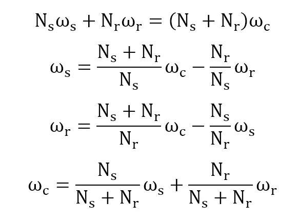
and
- Nr/ Ns = (ωs-ωc)/(ωr-ωc)
Considering ωr ≠ ωc
Alternatively, if the number of teeth on each gear meets the relationship Nr = Ns + 2Np, this equation can be re-written as the following:
nωs + (2+n) ωr – 2(1+n) ωc = 0
where,
n = Ns/Np
These relationships can be used to analyse any epicyclic system, including those, such as hybrid vehicle transmissions, where two of the components are used as inputs with the third providing output relative to the two inputs.
In many epicyclic gearing systems, one of these three basic components is held stationary; one of the two remaining components is an input, providing power to the system, while the last component is an output, receiving power from the system. The ratio of input rotation to output rotation is dependent upon the number of teeth in each gear, and upon which component is held stationary.
- One turn of the sun gear results in -Ns/Np turns of the planets
- One turn of a planet gear results in Np/Nr turns of the ring gear
So, with the planetary carrier locked, one turn of the sun gear results in -Ns/Nr turns of the ring gear.
The ring gear may also be held fixed, with input provided to the planetary gear carrier; output rotation is then produced from the sun gear. This configuration will produce an increase in gear ratio, equal to 1+Nr/Ns.
If the ring gear is held stationary and the sun gear is used as the input, the planet carrier will be the output. The gear ratio in this case will be 1/ (1 + Nr/Ns) which can also be written as 1:(1 + Nr/Ns). This is the lowest gear ratio attainable with an epicyclic gear train. This type of gearing is sometimes used in tractors and construction equipment to provide high torque to the drive wheels. But here the float and fix option are used instead of the gear mate. And the input speed values are given to the sun gear and ring gear. Similarly, the two output values are get from carrier and ring gear. I had used the metric system in design modeler to design these planetary gears.
Module is the unit of size that indicates how big or small a gear is. It is the ratio of the reference diameter of the gear divided by the number of teeth. Using this statement, we need to find out the planet gear dimension values. Here are the given input parameters to initiate this process,
- Ring Gear
Module(m) = 2.5 (The module is the same for all the gears)
Number of teeth(zr) = 46
Diameter(dr) = m*zr = 2.5*46 = 115mm
- Sun Gear
Number of teeth(zs) = 14
Diameter(ds) = m*zs = 2.5*14 = 35mm
Input Speed of the Gear = 200 rpm.
- Planet Gear
Diameter(dp) = (dr-ds)/2 = (115-35)/2 = 40mm
Number of teeth(zp) = dp/m = 40/2.5 = 16
Number of planet gears = 4
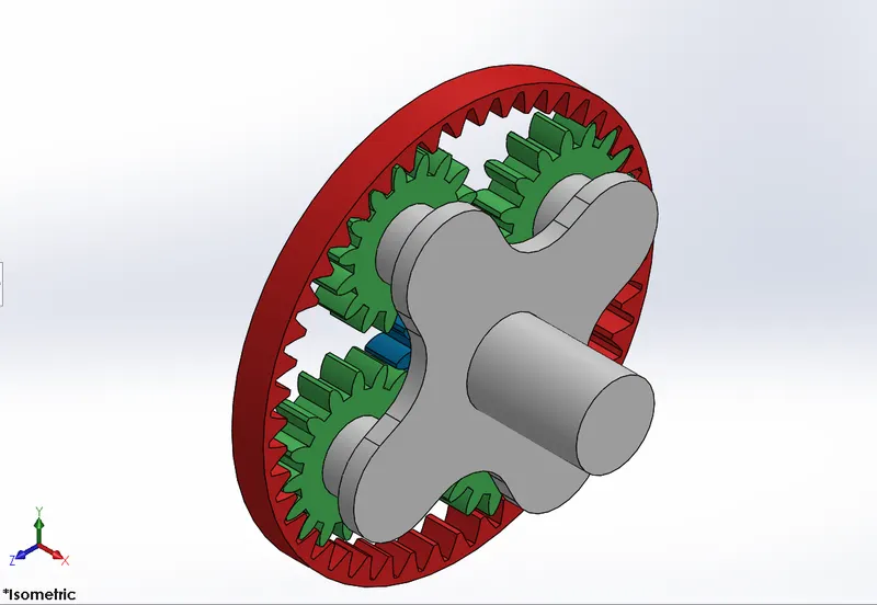
I am going to run a simulation on the following cases,
 Case-i: input speed of the sun gear = 200rpm
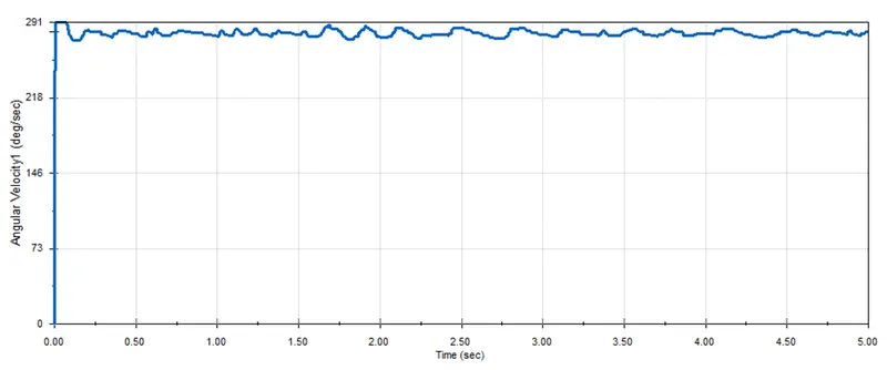
link:Angular velocity of carrier
Case-ii: input speed of the ring gear = 200rpm
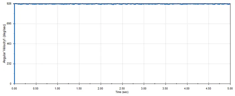
link:Angular velocity of carrier
Case-iii: input speed of the sun gear = 200rpm

link:Angular velocity of ring gear
CONCLUSION
The resultant plots of angular velocity of output gears are derived on all three conditions. That results are given below.
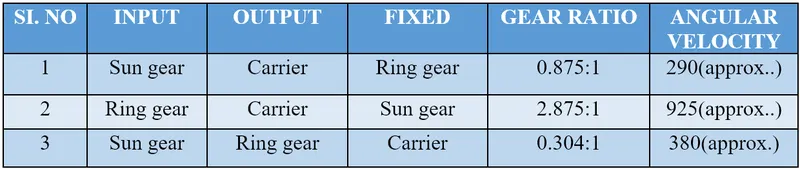 In the first two conditions both the input and output shaft rotate at same direction. But in the third condition both the shaft rotate at opposite direction it called reverse gear. i) the output carrier shaft rotates 0.875 times whereas the input shaft complete 1rev. so the angular velocity of the carrier comes with 290deg/sec approximately. here we can achieve the minimum speed. ii) the output carrier shaft rotates 2.875 times whereas the input shaft complete 1rev. so the angular velocity of the carrier comes with 925deg/sec approximately. here we can achieve the maximum speed. iii) the output ring gear shaft rotates 0.304 times whereas the input shaft complete 1rev. so the angular velocity of the carrier comes with 380deg/sec approximately. here we can achieve the reverse speed.
From the result we can see clearly in both first and third condition the inputs are same but outputs are different. The twist is the gear ratio in first condition is higher than the third one but the angular velocities are in opposite range. Because in the first condition all the planet gears turn and spin about its axis, but in the third condition the ring gear can only make turn. So the angular velocity of ring gear is high.