Photo Realistic Rendering
Modelling and assembling of American chopper
AIM:
To create a model of American chopper and rendering it.
FLOW CHART:
The below flowchart shows the design method followed in chopper assembly from sketching to Assembly.
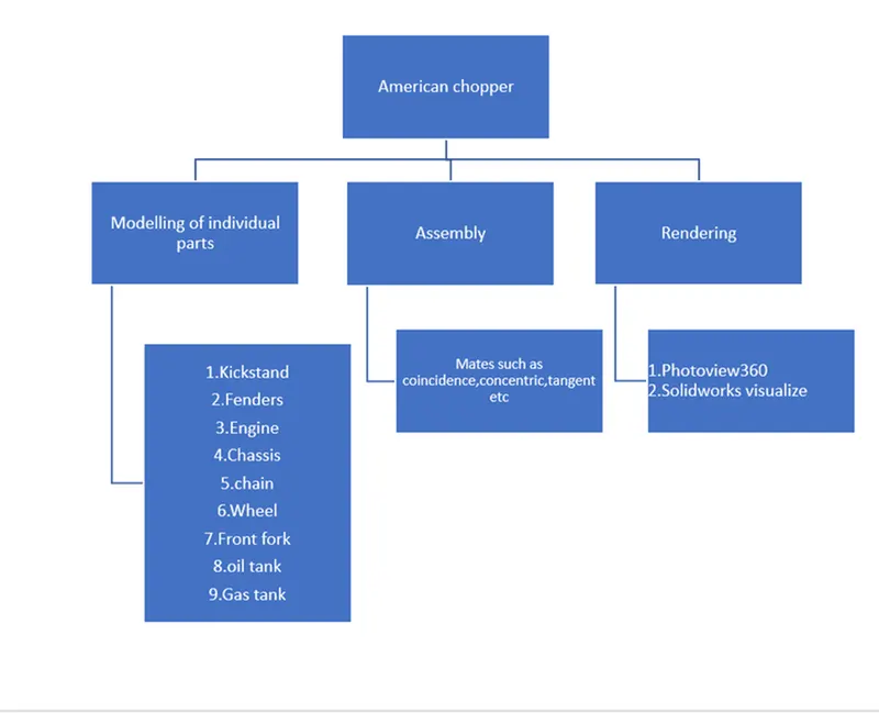
The chopper contains the following parts are designed as per the video
1.Transmission belt
2.Kickstand
3.Rear fender
4.Front fender
5.Chain
6.Pedal
7.Oil Tank
8.Front Wheel
9.Rear Wheel
10.Front Fork
11.Chasis
12.Engine
13.Gas Tank
Explanation of tools used:
- Creating a 2Dsketch:A 2D sketch is the base to create a 3D model. It is usually created on the X-axis & Y-axis. This includes lines, circles, rectangles, splines, etc.
- The Status of a Sketch
The current status of a sketch is displayed in the lower right corner of the screen.
Fully Defined = Black
Under Defined = Blue
Over Defined = Red
2.Geometric relation: Geometric relations are one of the most powerful features in SOLIDWORKS. They’re used in the sketch level to control the behaviours of the sketch entities when
they are moved or rotated and to keep the associations between one another
- Solid Extrude:It extrudes a sketch or selected sketch contours in one or two directions to create a solid feature
- Create a sketch. You can use a closed profile sketch or an open profile. For cuts, open profile sketches are only valid for Blind or Through All end conditions
- Click one of the extrude tools Insert >Boss/Base > Extrude
- Click ok
4.Extrude cut: Extrude cut is a feature which helps to remove materials from the 3D model. It is just opposite to extrude boss/base feature, because it cuts a sketch profile while extruding. It can cut in both directions and mainly used for creating holes, channels, slots etc.
- Sketch on planes and/or planar surfaces
- The sketch should be closed and defined
- Then select the cut extrude command, to cut the solid
5.Revolve Boss: Revolves a sketch or selected sketch contours around an axis to create a solid feature.
- Create a new 2D sketch.
- Create all solid sketch geometry on one side of the axis.
- Choose Revolve Boss/Base from the features menu.
- Pick the axis you wish to use for the revolve.
- Specify direction and angle.
- Accept the Feature
6.Revolve Cut: Cuts a solid model by revolving a solid profile around an axis.
7.Swept Boss: This feature sweeps a closed profile along an open or closed path to create a solid feature.
- Create a line or spline sketch.
- Select the profile need to extrude
- Select the path with extrude need to be done
8.Loft: The loft feature creates a shape by making transitions between multiple profiles and guides curves thus allowing to create complex geometry with a single tool.This feature can be used in both solid as well as surface modelling.
9.Dome: A dome is a rounded vault forming the outside face of a body or structure, typically with a circular base.
- Click Dome on the Features toolbar, or click Insert > Features > Dome.
- Select one or more planar or non-planar faces. Set a value for the distance by which the dome expands.
- Click to create a concave dome
- Curve driven: The Curve Driven Pattern tool allows you to create patterns along a planar or 3D curve. To define the pattern, you can use any sketch segment, or the edge of a face (solid or surface), that lies along the plane. You can base your pattern on an open curve, or on a closed curve, such as a circle.
- Linear pattern: Use linear patterns to create multiple instances of one or more features that you can space uniformly along one or two linear paths.
- circular patterns: Use circular patterns to create multiple instances of one or more features that you can space uniformly around an axis.
13.Fillet : Fillet/Round creates a rounded internal or external face on the part. You can fillet all edges of a face, selected sets of faces, selected edges, or edge loops
- Click fillet (Features toolbar) or Insert > Features > Fillet.
- Under fillet Parameters, select an item and set parameters
- click ok
14.Chamfer: The chamfer command is used to connect two adjacent faces using an inclined line.
- Click Chamfer (Features toolbar) or Insert > Features > Chamfer.
- Under Chamfer Parameters, select an item and set parameters
- click ok
15.Trim: The trim command is used to remove or erase the extra edges of intersecting lines on a 2D sketch. You can use Power trim to trim multiple, adjacent sketch entities by dragging the pointer across each sketch entity.
16.Offset: Adds sketch entities by offsetting faces, edges, curves, or sketch entities to a specified distance.
- The Offset entities tool is as simple as clicking the geometry after initiating the command
17.split: Use the Split feature to create multiple parts from an existing part. You can create separate part files, and form an assembly from the new parts.
- Click Split (Features toolbar) or Insert > Features > Split.
- In the Property Manager, set the options.
Callout boxes appear in the graphics area for up to 10 bodies at one time. Click Next 10 or Previous 10 to scroll through all the callout boxes for a part.
- Under Resulting Bodies, select the bodies to save under, or click Auto-assign Names.
All of the saved bodies appear in the graphics area and are listed in the Feature Manager design tree under Solid Bodies. The software automatically names all bodies. You can change the names.
- Double-click the body name under File, type a name for the new part in the dialog box, then click Save.
The new part name appears in the Resulting Bodies list and in the callout box. Unsaved bodies are not split and remain with the original part.
If you clear the check box for a split part after you save it, that part is no longer saved as a separate entity. It remains with the original part.
- Click ok.
18.Solid Merge/Combine: In a multibody part, you can combine multiple bodies to create a single body.
- Click Combine. (Features toolbar) or Insert > Features > Combine.
- In the Property Manager, under Operation Type, select Add.
- For Bodies to Combine, select the bodies to combine. You can select bodies in the graphics area or the Solid Bodies. ...
- Click Show Preview to preview the feature.
- Click ok.
19.project curve: You can project a sketched curve onto a model face to create a 3D curve. You can also create a 3D curve that represents the intersection of two extruded surfaces generated by creating sketches on two intersecting planes.
Use selection to create a curve that represents the intersection of sketches from two intersecting planes.
- Create a sketch on each of two intersecting planes, closing each sketch when you are done.
- Align the sketch profiles such that when they are projected normal to their sketch plane; the implied surfaces will intersect, creating the required result.
- Under Sketch to Project, select both sketches in the flyout Feature Manager design tree or the graphics area.
- Select Reverse projection to reverse the direction of projection.
- Select Bi-directional to create a projection that extends on both sides of the sketch
- Click ok.
20.Converting Entities: You can create one or more curves in a sketch by projecting an edge, loop, face, curve, or external sketch contour, set of edges, or set of sketch curves onto the sketch plane.
- In an open sketch, click a model edge, loop, face, curve, external sketch contour, set of edges, or set of curves
- Click Convert Entities (Sketch toolbar) or Tools > Sketch Tools > Convert Entities
- In the Property Manager, click Select chain to convert all contiguous sketch entities.
- Click ok.
21.Shell: The shell tool hollows out a part, leaves open the faces you select, and creates thin-walled features on the remaining faces. If you do not select any face on the model, you can shell a solid part, creating a closed, hollow model. You can also shell a model using multiple thicknesses
- Click Shell (Features toolbar) or Insert > Features > Shell.
- Set Thickness to set the thickness of the faces you keep.
- Select one or more faces in the graphics area for Faces to remove
- click ok.
22.Mirror: This allows to mirror features, faces & bodies along a face or a plane.
- click Mirror (Features toolbar) or Insert > Pattern/Mirror > Mirror.
23.Surface Knit: Combines two or more adjacent, non-intersecting surfaces together.
- Click Knit Surface on the Surfaces toolbar, or click Insert > Surface > Knit.
- In the Property Manager, under Selections: Select faces and surfaces for Surfaces and Faces to Knit
- Select Gap Control to view edge pairs that might introduce gap problems, and to view or edit the knitting tolerance or gap range. View the Knitting tolerance. Modify it if required
- Click OK
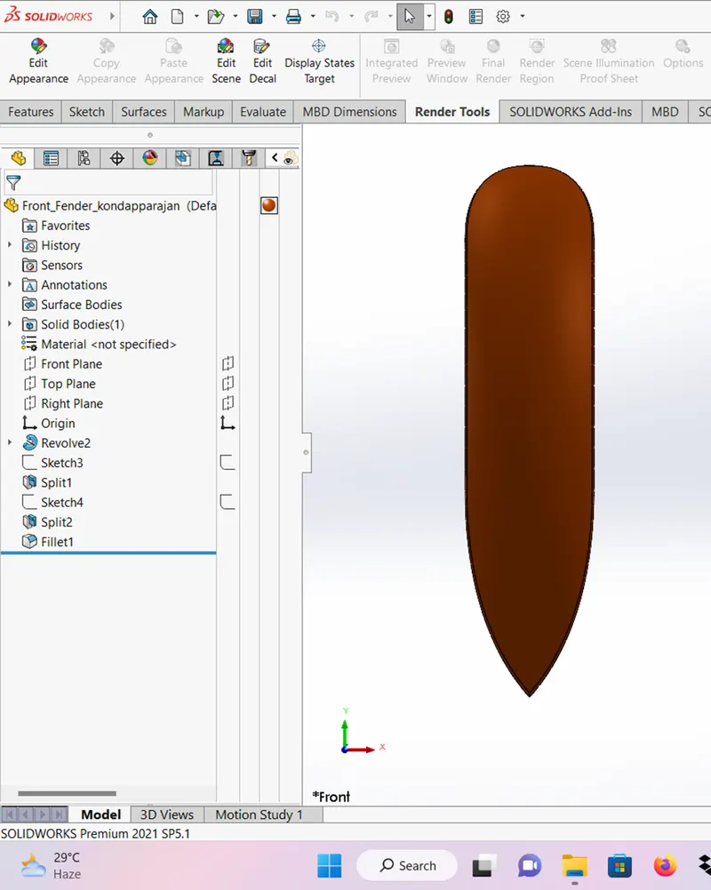
FRONT FENDER:
The Front fender is an automobile part mounted on the fork above the wheel. Its purpose is to protect rider and bicycle from mud, sand, or liquids.
- Feature Tool:- Fillet, Revolve Boss/Base, and Split.
- Sketch Tool:- Spline, Three-point arc, and Line.
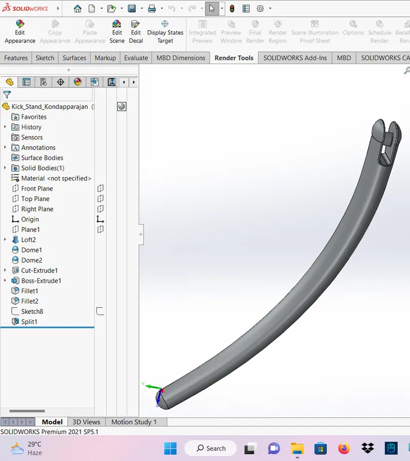
KICKSTAND:
A kickstand is a supporting structure provide to a bike which flips down from the frame and makes contact with ground when stationary. It is also known as side stand.
- Feature Tool:- Extruded boss/base, Loft Boss/Base, Extruded Cut, and Pierce
- Sketch Tool:- Rectangle, Circle, Spline, and Ellipse.
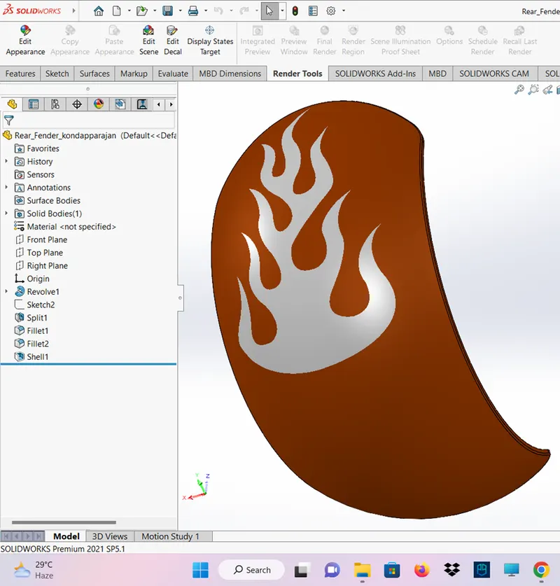
REAR FENDER:
- Feature Tool:- Fillet, Revolve Boss/Base, Shell, and Split.
- Sketch Tool:- Spline, Three-point arc, Offset Entities, and Line.
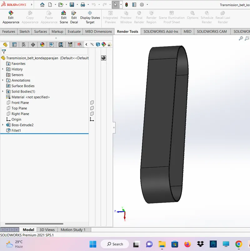
TRANSMISSION BELT:
It is made up of flexible material and used to transmit power efficiently from a motor to drive shaft/ pulley or to track relative movement. Sometimes it’s called as drive belts, gear belts or automotive belts.
- Feature Tool:- Extruded boss/base and fillet
- Sketch Tool:- Line, arc, and offset entities.
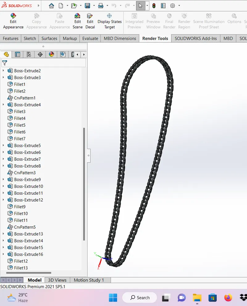
CHAIN:
Chains are used as the part of the drive train to transmit the motor power to the back wheel.
- Feature Tool:- Fillet, Extruded Boss/Base, Mirror, Block, Delete/Keep Body, and Curve Driven Pattern.
- Sketch Tool:- Straight Slots, Three-point arc, Circle, and Line.
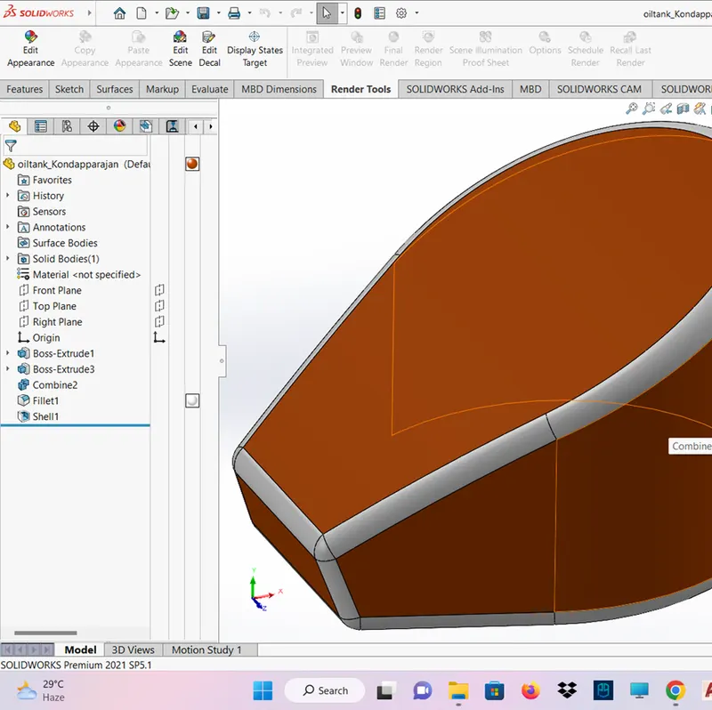
OILTANK:
- The oil tank stores the oil which is to be supplied to the engine for cooling & lubrication purposes.Features like Fillet, Boss Extrude & Combine were used to model the part.
- Features used for this model are Boss extrude, shell, combine, fillet
- Feature Tool:- Fillet, Shell, Combine, and Extruded Boss/Base.
- Sketch Tool:- Spline, Circle, and Line.
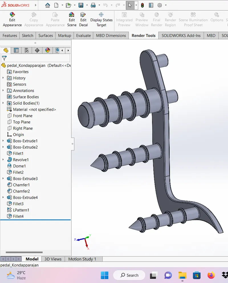
PEDAL:
The pedal is the part of a chopper and it is used to rest the leg on top of that.
- Feature Tool:- Fillet, Revolve Boss/Base, Extruded Boss/Base, Dome, Linear Pattern, and Chamfer.
- Sketch Tool:- Spline, Circle, and Line.
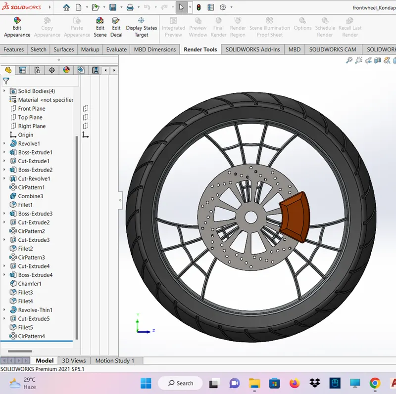
FRONT WHEEL:
The front wheel consists of tire, rotor, caliper, rim and it is designed by using the following sketch tools
- Feature Tool:-Fillet, Revolve Boss/Base, Chamfer, Extruded Boss/Base, Revolve Cut, Circular Pattern, Linear Pattern, and Mirror.
- Sketch Tool:- Spline, Three-point arc, Line, Rectangle, Convert Entities, Offset Entities, Trim Entities, and Circle.
REAR WHEEL:
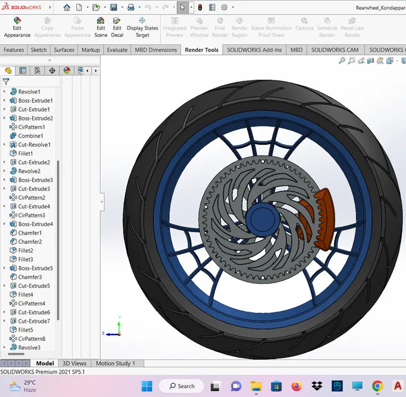
The rear wheel is a rolling part of chopper situated in rear side. The part revolves on an axle. The wheel contains – Caliper, Rim, Rotor, Disc, Sprocket and tire. Chain is connected between engine and sprocket of rear wheel.
- Feature Tool:- Fillet, Revolve Boss/Base, Chamfer, Extruded Boss/Base, Revolve Cut, Circular Pattern, Linear Pattern, and Mirror.
- Sketch Tool:- Spline, Three-point arc, Line, Rectangle, Convert Entities, Offset Entities, Trim Entities, and Circle.
FRONT FORK:
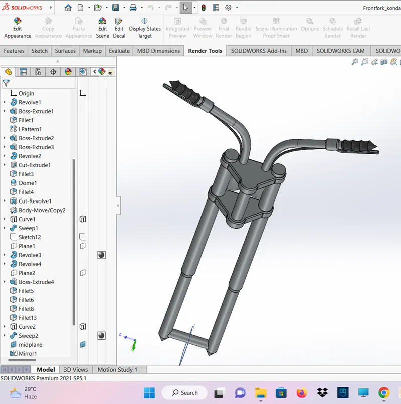
- The structure which connects the chassis and the front wheel of the bike. It has various mountings on it like headlights, break wire and levers, shock absorbers etc.
- Feature Tool:- Plane, Fillet, Extruded Boss/Base, Extruded Cut, Revolved Cut, Composite Curves, Projected Curves, Swept Boss/Base, Revolve Boss/Base, Chamfer, Mirror, and Combine.
- Sketch Tool:- Spline, Circle,3-Point Arc, Convert Entities, Offset Entities, and Line.
CHASSIS:
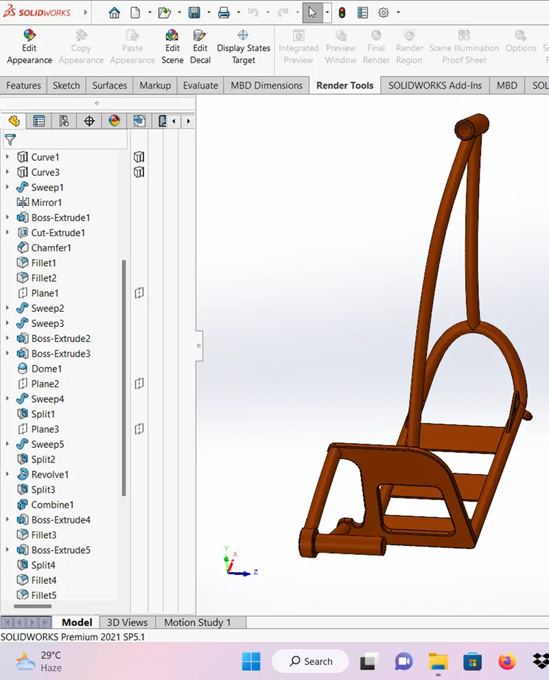
The Chassis is also called as frame. The components like front fork, gear box, engine, gas tank, wheels, etc are attached to it. It mostly consist of hollow tube.
- Feature Tool:-Split, Plane, Fillet, Extruded Boss/Base, Dome, Extruded Cut, Revolved Cut, Composite Curves, Projected Curves, Swept Boss/Base, Revolve Boss/Base, Chamfer, Mirror, and Combine.
- Sketch Tool:-Spline, Circle,3-Point Arc, Convert Entities, Offset Entities, and Line.
ENGINE:
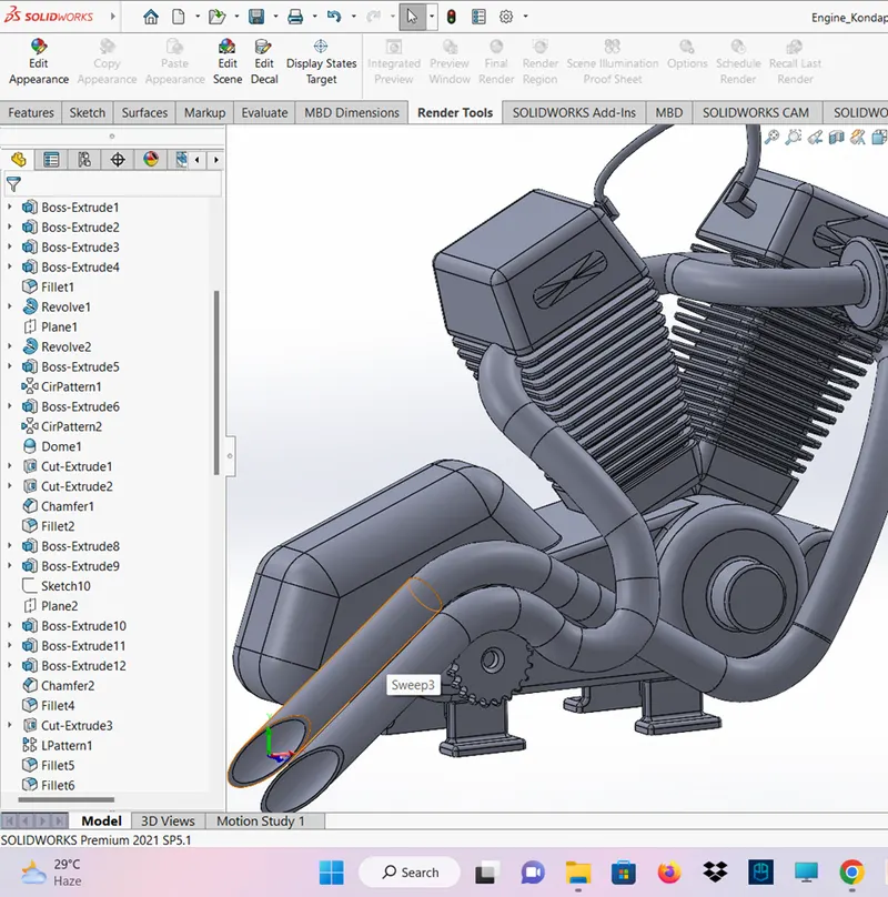
- The engine, apparently known as the heart of a vehicle includes parts such as spark plug, inlet valve, outlet valve, cylinder & motor. Motorcycle engines are typically two-stroke or four-stroke internal combustion engines
- Feature Tool:- Fillet, Extruded Boss/Base, Dome, Extruded Cut, Revolved Cut, Composite Curves, Projected Curves, Swept Boss/Base, Revolve Boss/Base, Chamfer, Mirror, and Combine.
- Sketch Tool:- Spline, Circle,3-Point Arc, Convert Entities, Offset Entities, and Line.
GAS TANK:
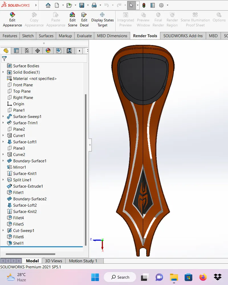
The gas tank or fuel tank is used to store the fuel and it is required to run the engine.
- Feature Tool:- Fillet, Swept Surface, Combine, Projected Curve, Mirror, Surface Knit, Swept Cut, Shell, and Boundary Surface.
- Sketch Tool:- Spline, Circle, Convert Entities, Offset Entities, and Line.
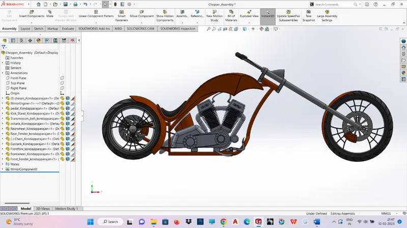
ASSEMBLY WITHOUT DECALS:
ASSEMBLY WITH DECALS:
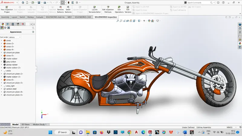
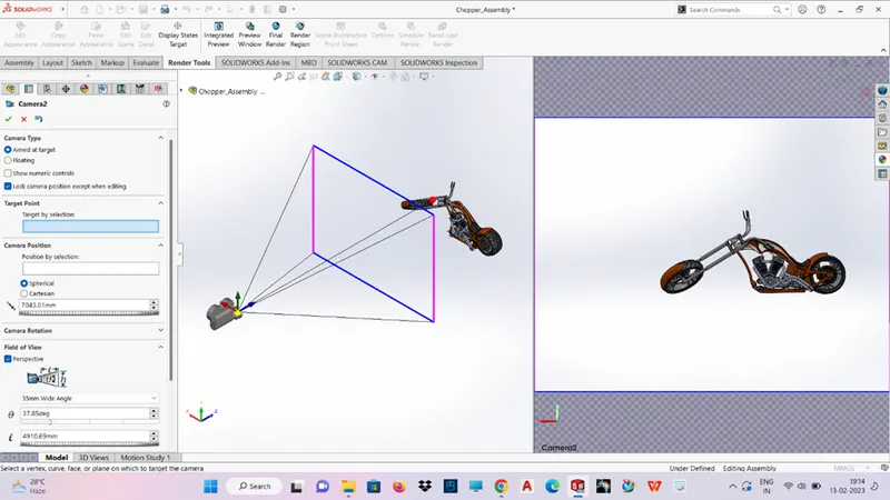
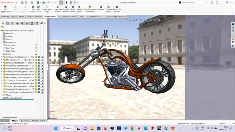
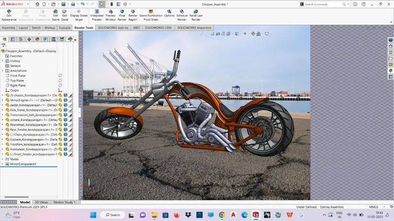
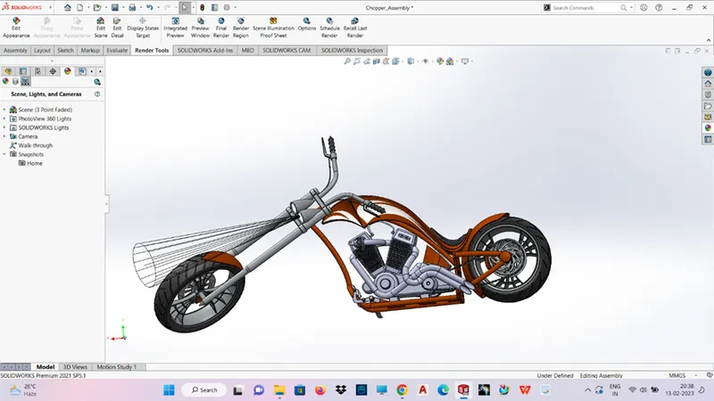
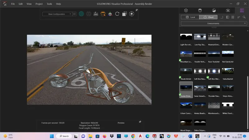
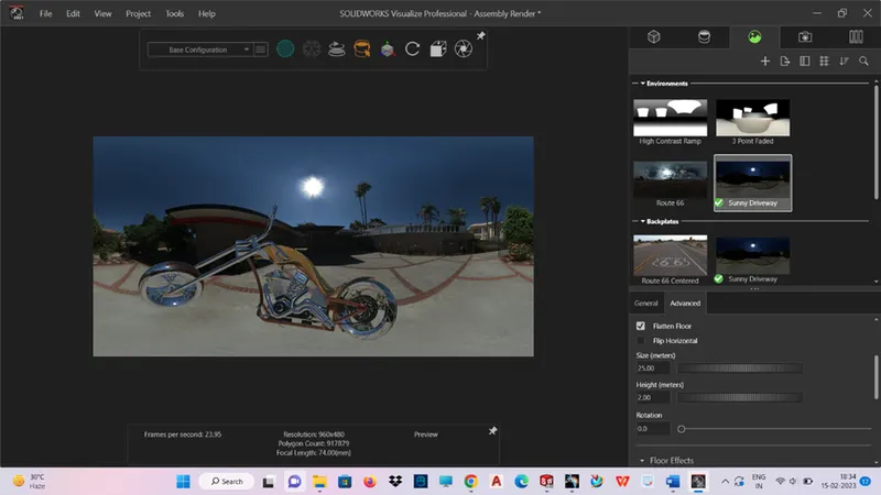
RENDERING:
NOTE:
Not able to send a file in sigle zip folder.so I have send it into two files as chopper assembly and rendering file.