Photo Realistic Rendering
Modelling of American Chopper in SolidWorks
Objectives :
1. To create a individaul parts of chopper using solidworks.
2. To assemble of the all individual parts into chopper.
3. To application of Decals,lights,scenes and camera etc.
4. To create a Photorealistic model and render it using photoview
360 and Solidwork visualize.
Introduction :
SolidWorks is a Software tool to modelling .Which 3D parts using
2D Sketch. If the materials looks and are to created.In this few
features ads like photoview 360 which helps to rendering images.
Which the images looks as Photorealistic. In this project we have
learnt , a Individaul parts ,Assembly of American Chopper.
Design model in Flow chart :
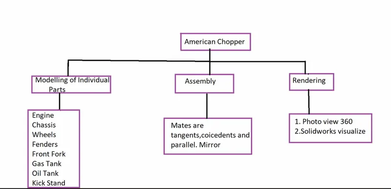
Details of Solidworks in Features Used-Sketch :
In SolidWorks to create a 2D Sketch representation uses a
Sketch Entites. Some of the Features are used 3D parts creates.
Few Entites are listed :
line
points
circles
Rectangles
Splines
Arcs
Straight Slot
Eclipse
Polygon etc.
Fatures :
Extrude-Boss : Selects a Sketch Contours in one or two directional
to create 3D part.If the Drag extrude required property manager.
Revolved-Boss : Selects a sketch Contours in Axe revolve to create 3D
part.If the Drag extrude required property manager.
Swept-Boss : To create a closed profile in open or closed path of
the Solid Feature. If the curves, Orientations etc options in the
property manager to select .
Lofted-Boss : Adds a materials one or more profiles of the Solid Feature.
If the profiles selects first or last and last or first points.
Offset : If the offsets is used to increase or reduce the Sketchs in the Profile.
Boundary-Boss : Adds a materials in Two directionals to create Solid Features
Which can creates surfaces of boundary.
Extrude-Cut :Extrude Cut is to create profile sketch to extrude cut a bodies
in one or two directional.If the Extrude cut is multiple bodies to cut , as we
select a Dialogue box
Revolved-Cut : Revolve Cut is to create profile sketch Axe revolve to extrude
cut a bodies in one or two directional.If the Extrude cut is multiple bodies to cut ,
as we select a Dialogue box
Fillets : Creates a rounded internal or external face along one or more edges,
if the sizes constant or variable changes.The property manager selects requiry
to the as we keep box.
Patterns : (Linear ,Circular and Sketch circular ): If the Patterns are faces ,bodies
to creates .Referance of the geometry Define Sketch.
Shell : Hallow of the part, leaving a open creates a thin part.
Mirror : Which define images to recreate a, required faces ,bodies
select to create a image.
If the References geometry commands and Curve geometry commonds are used etc .
Details in Surface Modellings :
If the Surfae modellings are same as features,but Surface are creates Required surfaces only.
Listed below :
Extrude Surface
Revolve Surface
Swept Surface
Lofted Surface
Boundary Surface
Filled Surface are the surface modellings etc .
INDIVIDUAL PARTS OF AMERICAN CHOPPER :
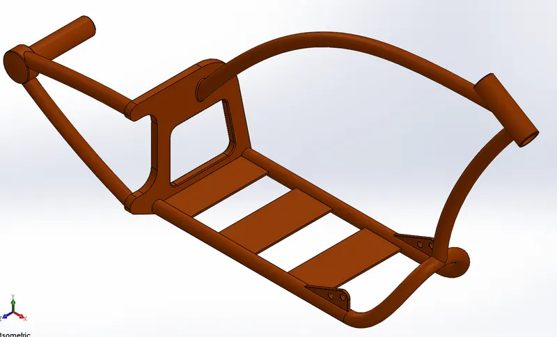
Chassis :
The Chassis is majaor part in this Chopper.Chassis is frame of Skeleton model all
components likely attached, Chassis is ability Strong the chopper.
Chassis is create to used Sketch Entites and features.
Boss Extrude
Curves
Sweeps
Mirrors
Cut Extrude
Fillets
Champer
Planes
Splits
Combine
Revolve
Engine :
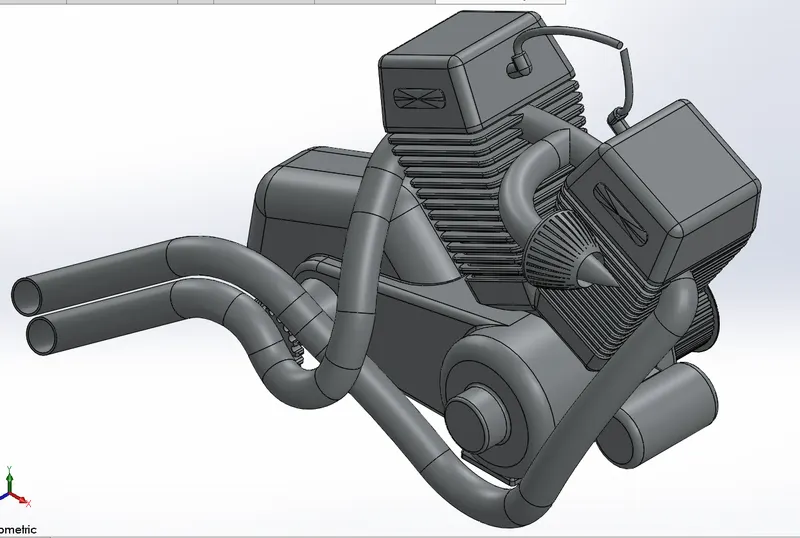
Engine is a Major part in Chopper . Engine is a machine which converts a various
Forms of energy into Machanical Force and Motion.
Engine to create uses Sketch Entites and Features.
Boss Extrude
Curves
Sweeps
Patterns : Linear and Circular.
Mirrors
Dome
Composite Curves
Cut Extrude
Fillets
Champer
Planes
Splits
Combine
Revolve
Gas Tank And Oil Tank :
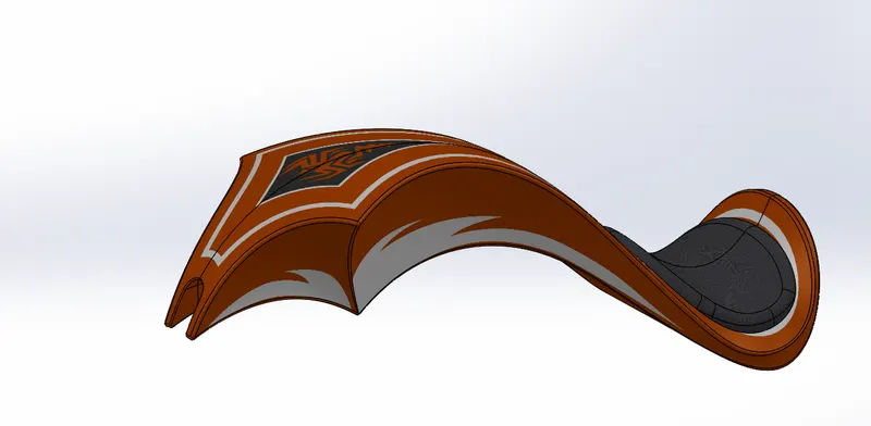
Fuel Tank is a Safe container for Flamable Fluids. It is a Typical Part of an Engine
System Which Fuel is stored Propelled or released a pressurised Gas to Engine.
Gas Tank to create uses Sketch Entites and Features.
Surface -Sweep
Surface-Trim
Planes
Curves
Boundary-Surface
Surface-Loft
Surface-Knit
Split Line
Cut-Sweep
Fillets
Shell
Oil Tank is oil container, Capacity of oil is holds to cool downs the Engine.
Engine performs a better, No tear and Wear and corrosion.
Oil Tank to create uses Sketch Entites and Features.
Boss-Extrude
Combine
Fillets
Shell
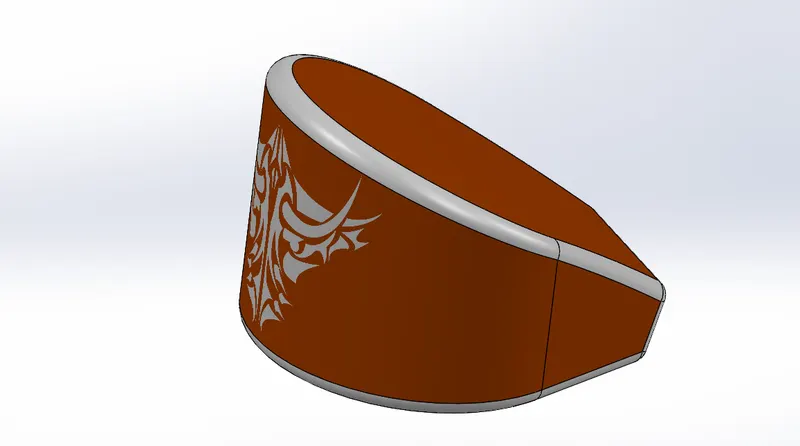
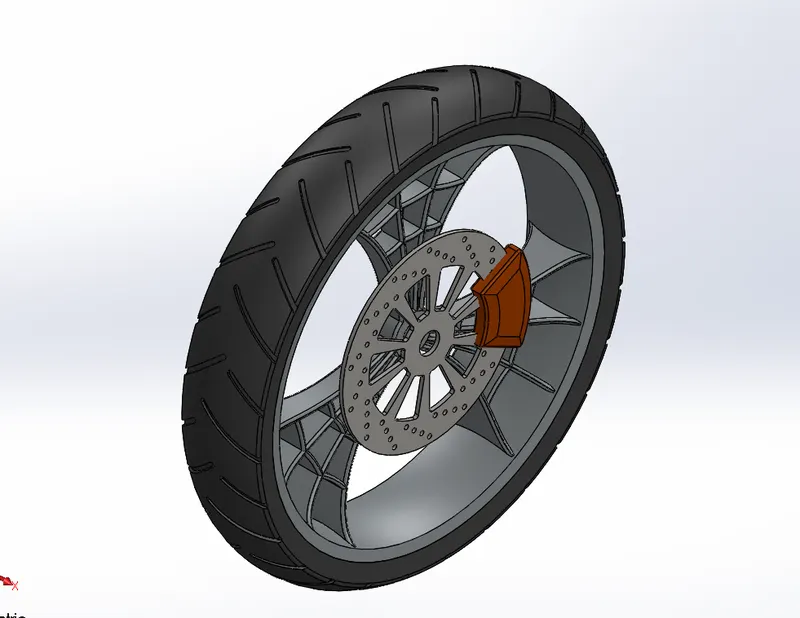
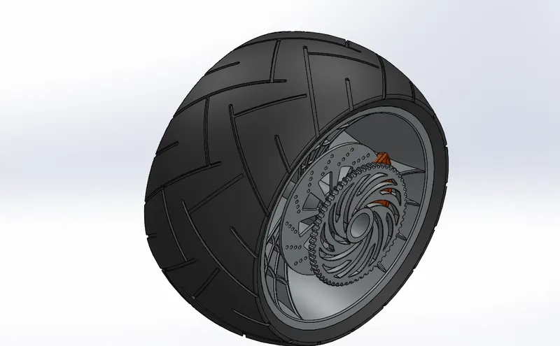
Front Wheel And Rear Wheel :
Front and Rear Wheels same , With Standard Front and Rear Wheels
rims are identical. Just make sure the number of spoke holes of the rim
matches your rear hub. Sometimes they use fewer spokes on the front.
Front and Rear Wheels to create uses Sketch Entites and Features.
Boss-Extrudes
Cut-Extrudes
Cut-Revolves
Revolves
Circular Patterns
Combines
Fillets
Champers
Axiss
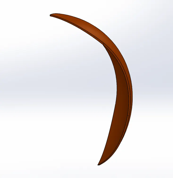
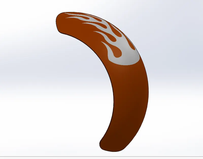
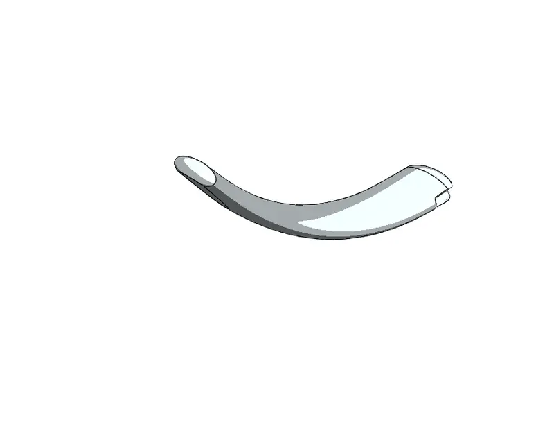
Front And Rear Fenders :
Front and Rear Fenders to create uses Sketch Entites and Features.
Revolve
Splits
Fillets
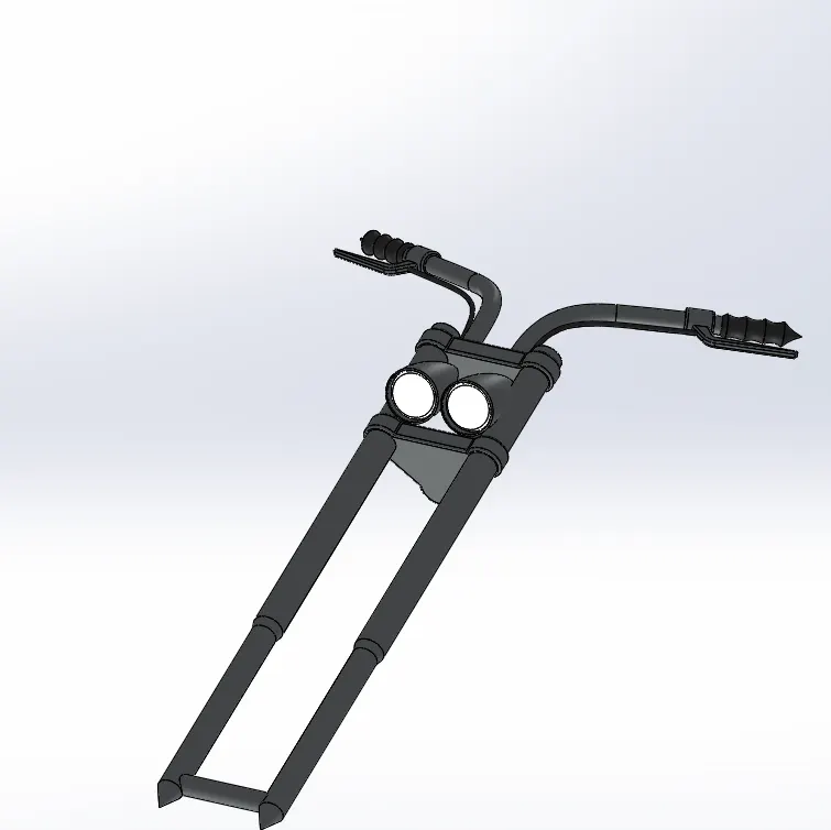
Front Fork :
Most forks incorporate the front suspension and front brake,
and allow the Front wheel to rotate about the steering axis
so that the bike may be Steered.
Front Fork to create uses Sketch Entites and Features.
Boss-Extrude
Revolve
Cut-Extrude
Linear pattern
Fillets
Curves
Planes
Sweeps
Dome
Mirrors
Combine
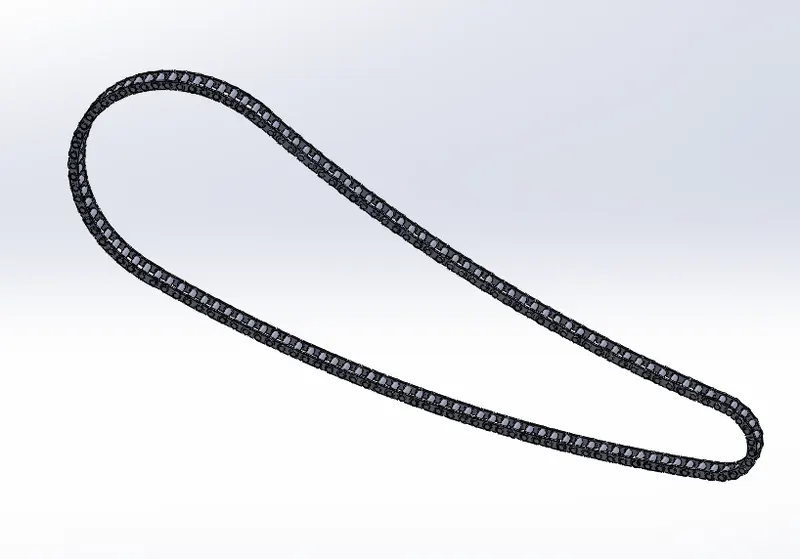
Chain Part :
The crankset is the part of the bike that your legs push around, in order to turn the rear wheel.
It consists of the chainrings (which the chain goes round), and the crank arms (which the pedals
attach to). The chainrings are the front gears of the bike.
Chain part to create uses Sketch Entites and Features.
Boss-Extrude
Fillets
Chain Links
Circular Pattern
Mirror
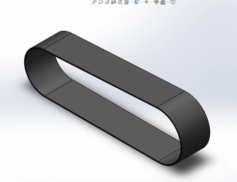
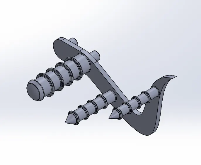
Transmission Belt , Pedal and Kickstand :
The drive belt, also known as the serpentine belt, Keeps the Engine runing is smoothly.
Some vehicles utilize a dual belt system, but most modern automobiles have a single belt.
It is a reinforced rubber belt that delivers power to the AC, cooling system,
power steering and alternator as the vehicle runs.
KickStand is used for Prop up the vechile When not used to Vichile, Bike to stands with rest.
ASSEMBLY OF AMERICAN CHOPPER
Assmebly parts are :
1.Kick Stand
2.Pedals
3.Transmission Belt
4.Front Fender
5.Rear Fender
6.Front Wheel
7.Rear Wheel
8. Gas Tank
9.Oil Tank
10.Chain Part
11.Front Fork
12.Engine
13.Chassis
Features Used in Assembly :
Insert Components : If the insert components to insert parts, to fix option to position.
Mates : Mates are to generates geometry relation assembly of position fix .
Without Disturbance , fix position. Various Mates are likely used in Assembly.
Standard Mates : Concentric, Tangent, Angle, Coincedent,parralel and distance.
Advance Mates : Limits , Width etc.
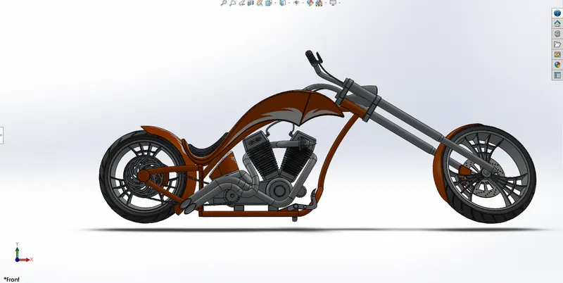
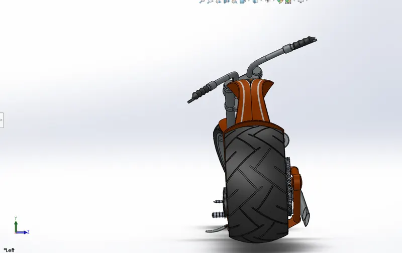
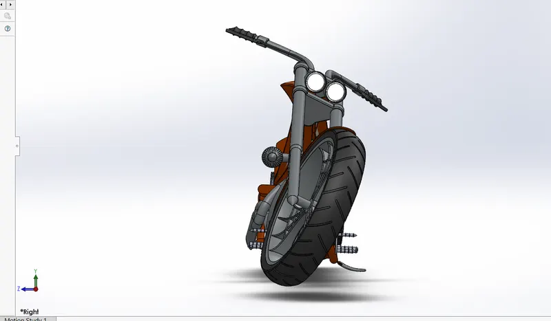
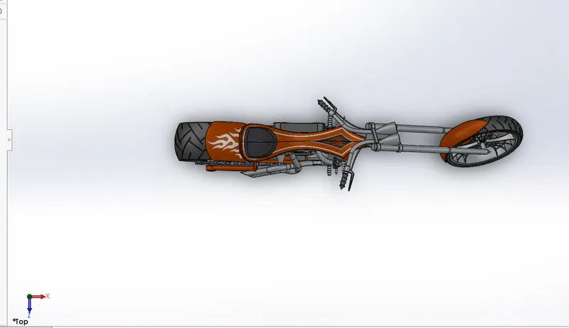
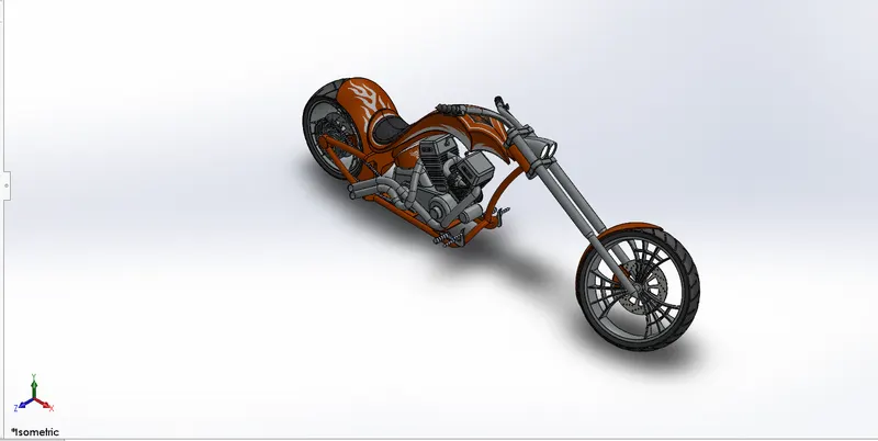
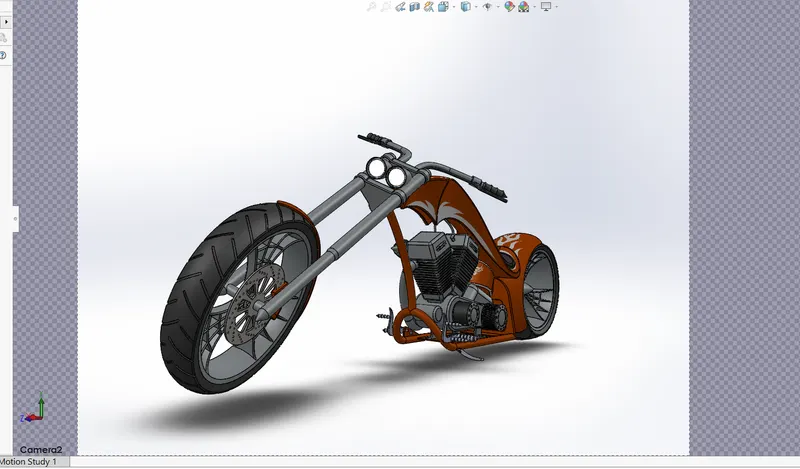
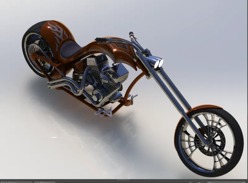
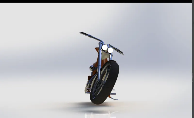
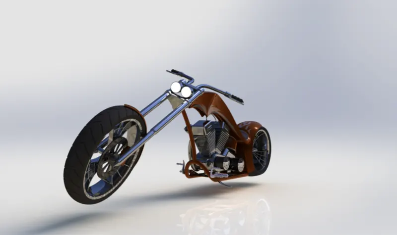
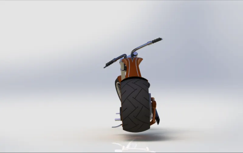
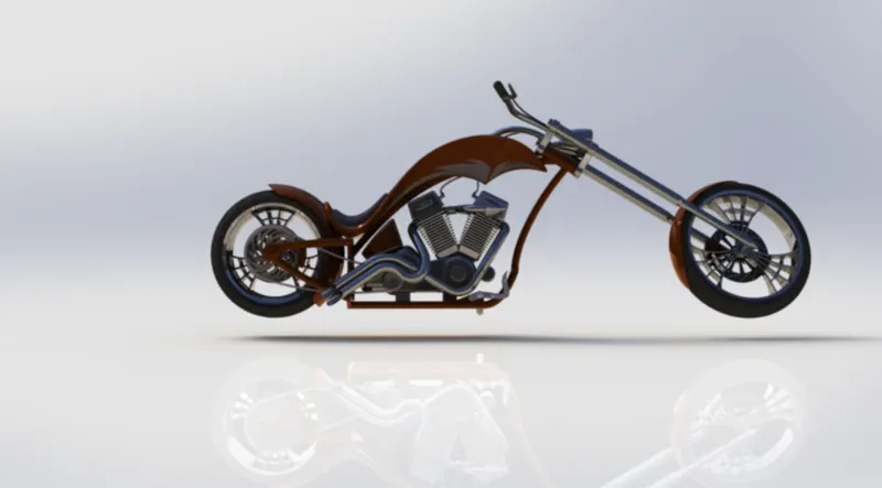
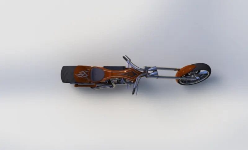
Figures are Iso, Front,Top, Sides and Camera views :
Decals in Assembly :
If the Decals are used in Assembly of American Chopper in Rendering tools, Decals Location of Face,
Decals applys to looks awesome.
Rendering for American Chopper :
Rendering is process of creating a realistic images of the model with Environment.
In rendering various aspects such as camera , light, environment , background
scene, apperance, etc. are taken in consideration before final rendering. To check
the all thing preview rendering options is used.
There are
1.Photoview 360
2.Solidworks visualize.
In photorealistic model, some of the mates and conditions are changed to render
realistic model. So we have to change as per differnt view before rendering.
Rendering images of Iso, Front ,Top,Sides and Camera views
Conclision :
- The parts are sketched and modelled in the Solidworks
- The modelled parts are assembled with possible mates in to the main
assembly of american chopper.
- The decals are applied to face of parts.
- The realistic images was rendered with use of both ways of
Photoview 360 and Solidworks Visualize.
PART FILES SENT IN ANSWER BOX