Photo Realistic Rendering
Modelling and Rendering of an American Chopper
Aim:
- To sketch and design the parts of the American chopper using Solidworks.
- To assemble the modeled parts of the chopper by using the Solidworks assembly environment.
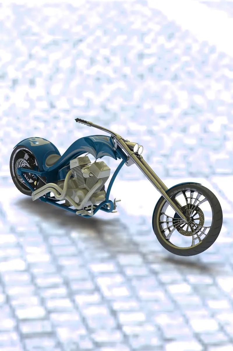
- To create photorealistic rendered images of the chopper using Solidworks visualize.
Introduction:
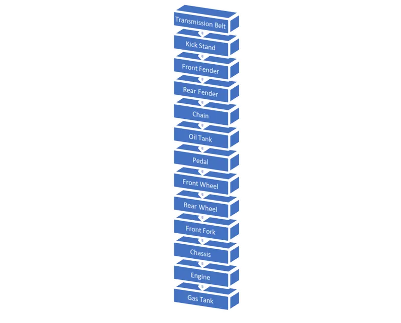
The chopper parts are modeled using part modeling. Once all the parts are modeled separately, they are assembled to create a chopper. The following parts are,
Design Approach:
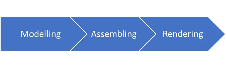
Part Modelling
Part modeling is the process of creating a virtual prototype of something by modeling each individual part separately, which can then assemble together to create the model of the final product.
Commands used in Modelling
- Sketch: The sketch is the basis for a 3D model. You can create a sketch on any of the default planes (Front Plane, Top Plane, and Right Plane), or a created plane. You can start by selecting: Sketch entity tools (line, circle, and so on).
- Trim Entities: You can use Power trim to trim multiple, adjacent sketch entities by dragging the pointer across each sketch entity
- Extend Entities: Extend command to edit entities so they have common boundary edges. Extend expands parts of entities to the intended boundary edge, letting you close polygons precisely or extend entities to the proper boundary edge. As drawing an entity expands, they do not change direction. A-Line remains a Line, and an Arc remains an Arc.
- Convert Entities: You can create one or more curves in a sketch by projecting an edge, loop, face, curve, or external sketch contour, set of edges, or set of sketch curves onto the sketch plane.
- Offset Entities: Offset entities take a copy of your existing geometry and copy it at an offset. Instead of recreating geometry, you can use this to quickly sketch based on model geometry. Offset entities are a great tool for enlarging or shrinking your sketch geometry.
- Linear Pattern: The Linear Pattern Command is used to drive features, faces, or bodies in a linear direction. This feature helps save time by cutting down the repetitive movements of adding a bunch of holes or other forms of geometry.
- Circular Pattern: A circular pattern is a radial array of objects around a Center point in a sketch. Axis in a part or assembly.
- Dynamic Mirror: It is similar to mirror entities however the line or lines to mirror about are selected beforehand then anything drawn in the sketch will be mirrored dynamically.
- Extruded Boss/Base: One of the oldest commands in the SOLIDWORKS software is the boss/base extrude command. An Extruded Boss/Base feature will allow you to take a 2D sketch and add thickness to it in the 3D.
- Extruded Cut: Extrude tool is used to extend a sketched profile in one or two directions as either a thin feature or a solid feature. An extrude operation can either add material to a part (in a base or boss) or remove material from a part.
- Revolve Boss/Base: Revolves add or remove material by revolving one or more profiles around a centerline. You can create revolved boss/bases, revolved cuts, or revolved surfaces. The revolving feature can be a solid, a thin feature, or a surface.
- Revolve Cut: It helps to remove materials from 3D models that possess axis symmetry.
- Swept Boss/Base: It helps to sweep a closed profile through an open or closed path.
- Loft Surface: A loft feature is an important tool for (surface) modeling in SolidWorks. The loft feature creates a shape by making transitions between multiple profiles and guide curves.
- Filled Surface: The Filled Surface feature constructs a surface patch with any number of sides, within a boundary defined by existing model edges, sketches, or curves, including composite curves.
- Surface Trim: A trimmed surface has two parts: a surface that underlies everything and defines the geometric shape, and trimming curves that mark sections of the underlying surface that are trimmed away. Trimmed surfaces are created with commands that trim or split surfaces with curves and other surfaces.
- Surface Knit: Knit surfaces absorb the surface bodies you used to create them. Create a solid body when the knit surfaces form a closed volume or leave as a surface body. Select Merge entities to merge faces with the same underlying geometry.
- Shell: The shell tool hollows out a part, leaves open the faces you select, and creates thin-walled features on the remaining faces. If you do not select any face on the model, you can shell a solid part, creating a closed, hollow model. You can also shell a model using multiple thicknesses.
- Split: Split tool projects an entity (sketch, solid, surface, face, plane, or surface spline) to surfaces, or curved or planar faces. It divides a selected face into multiple separate faces. You can split curves on multiple bodies with one command.
- Dome: The software calculates the distance using the radius of the arc as a basis for the dome. It creates a dome that is tangent to the adjacent cylindrical or conical face.
- Pierce Relationships: A pierce relationship is required to ensure that two entities from different axis collide or cross paths – the center point of entities can be selected to move the sketch entity to a mutual position. To apply a pierce relation a line and a sketch point are required.
- Projected Curve: You can create multiply closed or open-contour projected curves from a single sketch. You can also use 3D sketches as input for the Projected Curve tool. The Projected Curve tool does not support projections of intersecting curves. You can project curves from 2D and 3D sketches, onto faces and planes.
- Composite Curve: You can create composite curves by combining curves, sketch geometry, and model edges into a single curve. Use a composite curve as a guide curve when creating a loft or a sweep. To create a composite curve: Click Composite Curve on the Curves toolbar, or click Insert, Curve, Composite.
- Fillet: Fillet/Round creates a rounded internal or external face on the part. You can fillet all edges of a face, selected sets of faces, selected edges, or edge loops.
- Chamfer: The chamfer tool creates a beveled feature on selected edges, faces, or a vertex.
- Split Line: The Split Line. the tool projects an entity (sketch, solid, surface, face, plane, or surface spline) to surfaces, or curved or planar faces. It divides a selected face into multiple separate faces. You can split curves on multiple bodies with one command.
- Reference Plane: The most common type of reference plane is an offset plane. To create an offset plane, select the Reference Geometry drop down on the Command Manager and choose the Plane option. Once the option to create a plane is open, select a face or another plane and set a distance for the offset.
- Combine: The Combine tool helps us work with multibody part files. We have three operation types to choose from: Add, Subtract, and Common. Some might know Combine has a Boolean operation.
- Blocks: It behaves a lot like a block in AutoCAD and is an ideal way to group lines in a complex layout to sort by function. Blocks can also isolate their internal sketch relations, eliminating performance issues.
- Appearances: It displays the colors of faces, features, bodies, and parts.
Parts Description:
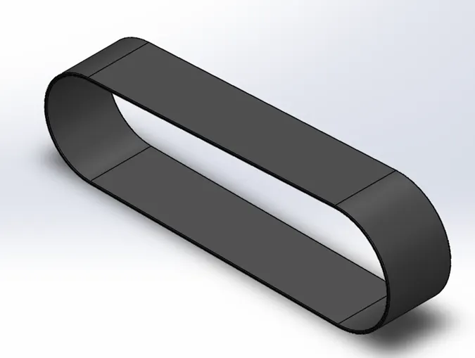
Transmission Belt:
A belt drive is a transmission system that uses a flexible strip to transfer power. The turning disk is connected by a belt drive to the electric motor. A rubber belt drive is used to transfer power from one pulley to another. A belt drive is a transmission system that uses a flexible strip to transfer power.
Commands Used:
- Sketch
- Offset
- Extrude Boss/Base
- Fillet
- Appearances
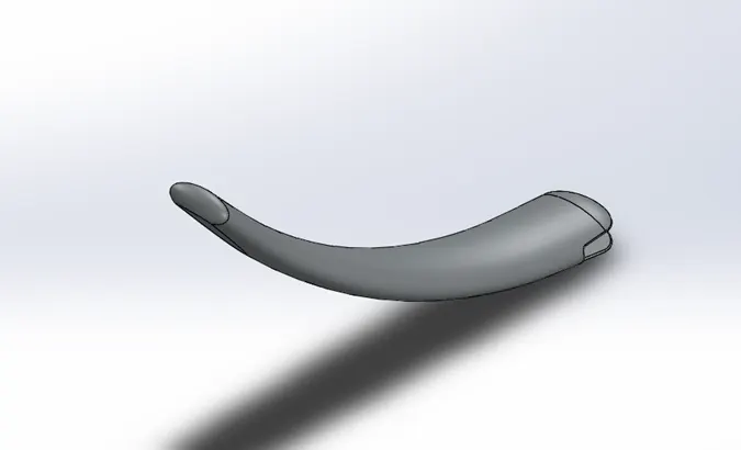
Kickstand:
It is a device that allows the bike to be kept upright without leaning against another object or without the aid of a person. A kickstand is usually a piece of metal that flips down from the frame and makes contact with the ground. It is generally located in the middle of the bike or towards the rear.
Commands Used:
- Sketch
- Loft
- Dome
- Extrude Boss/Base
- Extrude Cut
- Fillet
- Split
- Appearances
Front and Rear Fenders:
A fender is essentially a covering for your bike tires that protects you from the rain. Riding with fenders will prevent the rain from splashing a streak of muddy water up your back, over your shoes, and on your face.
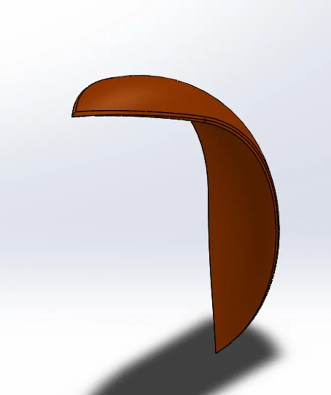
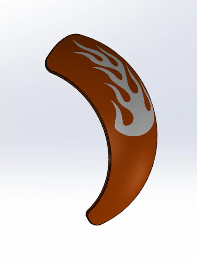
Commands Used:
- Sketch
- Offset Entities
- Trim Entities
- Revolve Boss/Base
- Dynamic Mirror
- Split
- Shell
Chain:
It consists of one or more sprockets, also called chainrings or chain wheels attached to the cranks, arms, or crankarms to which the pedals attach. It is connected to the rider by the pedals, to the bicycle frame by the bottom bracket, and to the rear sprocket, cassette or freewheel via the chain.
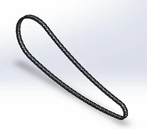
Commands Used:
- Sketch
- Trim
- Fillet
- Extrude Boss/Base
- Patterns
Oil Tank
A fuel tank (also called a petrol tank or gas tank) is a safe container for flammable fluids. Though any storage tank for fuel may be so-called, the term is typically applied to part of an engine system in which the fuel is stored and propelled (fuel pump) or released (pressurized gas) into an engine.
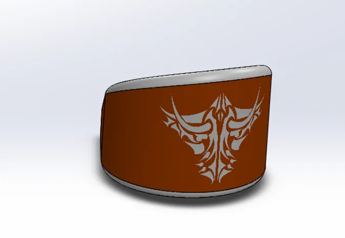
Commands Used:
- Sketch
- Extrude Boss/Base
- Combine
- Fillet
- Shell
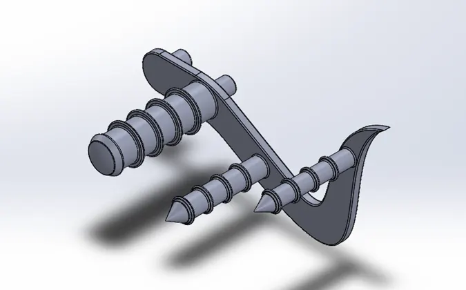
Pedal:
It is used to rest feet while driving a two-wheeler. It is an external part of the chassis.
Commands Used:
- Sketch
- Extrude Boss/Base
- Linear Pattern
- Fillet
- Dome
- Chamfer
- Appearances
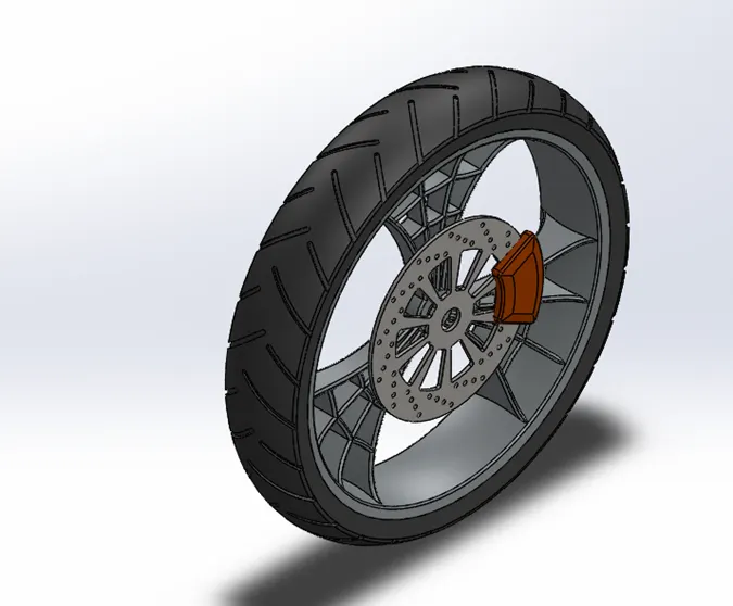
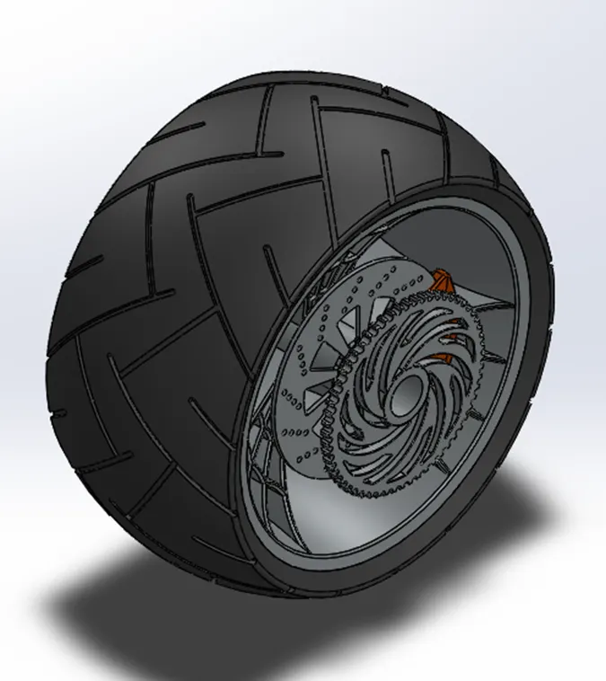
Front and Rear Wheel
They are made to cope with radial and axial forces. They also provide a way of mounting other critical components such as the brakes, final drive, and suspension. Wheels, and anything directly connected to them, are considered to be unsprung mass.
Commands Used:
- Sketch
- Revolve Boss/Base
- Trim
- Revolve Cut
- Extrude Boss/Base
- Extrude Cut
- Circular Pattern
- Fillet
- Appearances
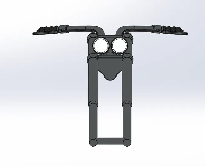
Front Fork
A motorcycle fork connects a motorcycle's front wheel and axle to its frame, typically via a yoke, also known as a triple clamp, which consists of an upper yoke joined to a lower yoke via a steering stem, a shaft that runs through the steering head, creating the steering axis.
Commands Used:
- Sketch
- Extrude Boss/Base
- Revolve Boss/Base
- Trim
- Split
- Plane
- Convert Entities
- Move/copy Body
- Dome
- Mirror
- Combine
- Projected curve
- Swept
- Fillet
- Appearances
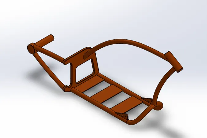
Chassis:
It is a motorcycle's core structure. It supports the engine, provides a location for the steering and rear suspension, and supports the rider and any passenger or luggage. Also attached to the frame are the fuel tank and battery. At the front of the frame is found the steering head tube that holds the pivoting front fork, while at the rear there is a pivot point for the swing arm suspension motion. Some motorcycles include the engine as a load-bearing stressed member; while some other bikes do not use a single frame, but instead have a front and a rear subframe attached to the engine.
Commands Used:
- Sketch
- Offset
- Revolve Boss/Base
- Extrude Cut
- Trim
- Split
- Plane
- Convert Entities
- Mirror
- Combine
- Projected curve
- Swept
- Fillet
- Appearances
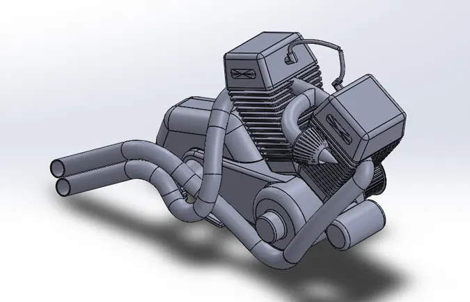
Engine:
Engines may be two-stroke or four-stroke internal combustion engines, but other types have been used in small numbers. The engine typically drives the rear wheel. Most engines have a gearbox with two to six ratios, reverse gear is rare but does exist for sidecar use. Power is sent to the driven wheel by belt, chain, or shaft. In Europe, before the 1969 Honda CB750, engine capacities typically ranged from about 50 cc to 750 cc; but since then, machines with capacities up to 2,300 cubic centimeters Triumph Rocket 3 have become common. In the USA, motorcycles with large capacities have been common for much longer.
Commands Used:
- Sketch
- Extrude Boss/Base
- Revolve Boss/Base
- Extrude Cut
- Offset
- Trim
- Split
- Plane
- Convert Entities
- Dome
- Mirror
- Combine
- Projected Curve
- Composite Curve
- Swept
- Fillet
- Circular Pattern
- Appearances
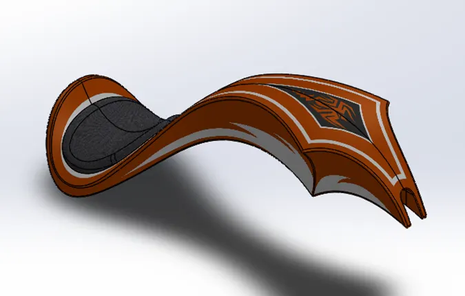
Gas Tank:
It is used to store the fuel. It gives fuel to the engine whenever requires.
Commands Used:
- Sketch
- Trim
- Split Line
- Plane
- Convert Entities
- Swept Surface
- Loft Surface
- Fill Surface
- Surface Trim
- Surface Knit
- Swept Cut
- Fillet
- Mirror
- Projected curve
- Fillet
- Shell
- Appearances
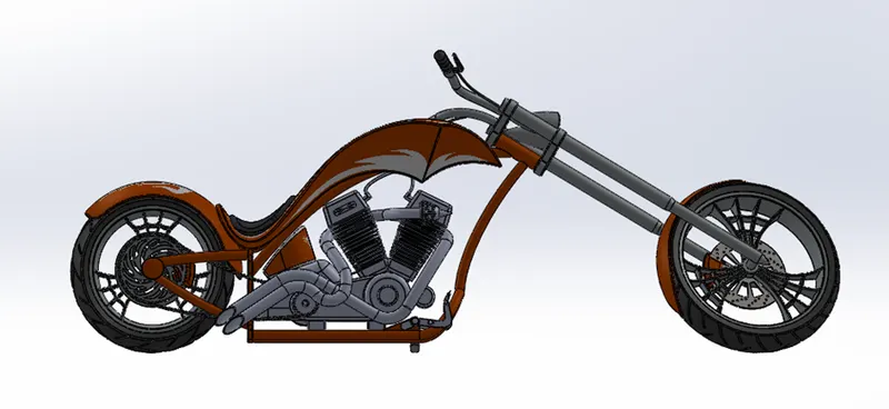
Assembly of American Chopper:
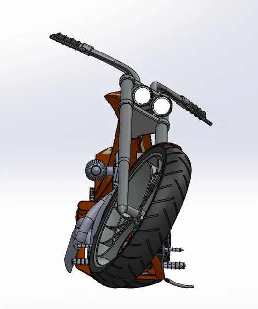
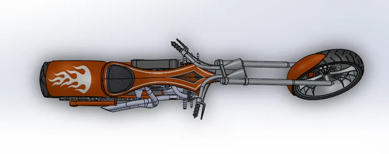
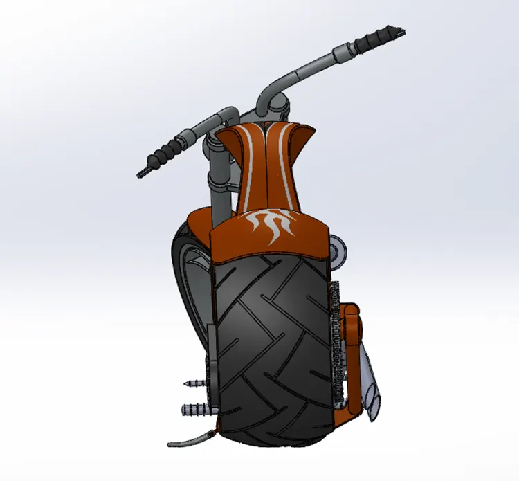
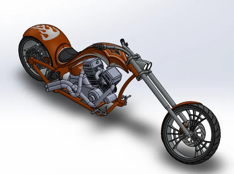
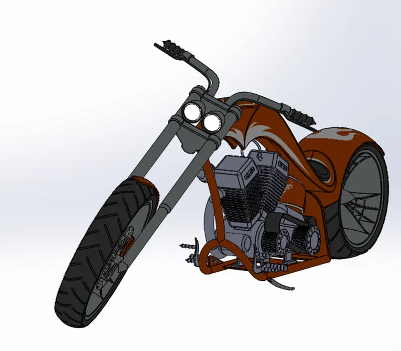
All the parts are inserted one by one in assembly. The parts were inserted randomly in the assembly environment and given standard mates by taking the chassis as a reference so that all the parts move with respect to the chassis only when the chassis floats.
Front View
Side View
Top View
Back View
Isometric View
Camera View
Photorealistic Rendering:
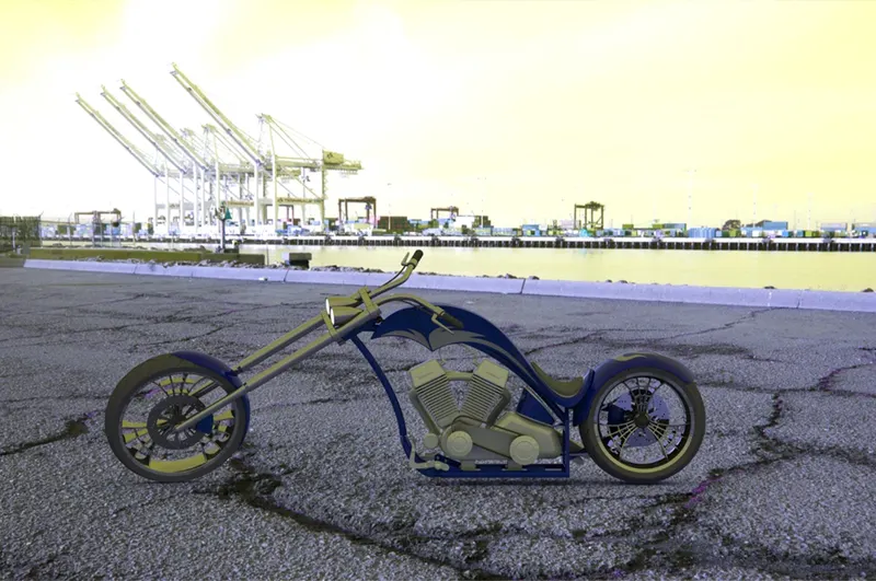
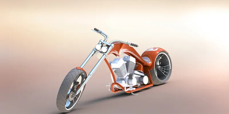
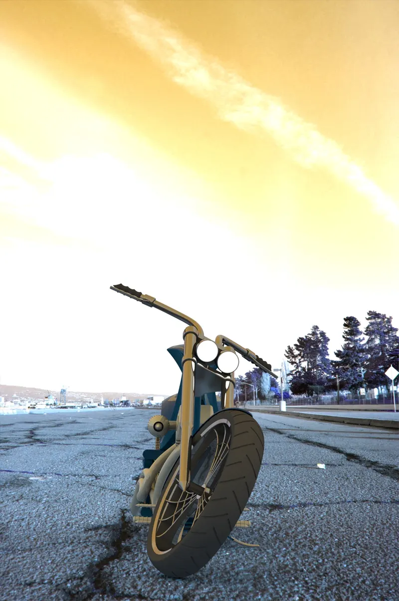
Rendering or image synthesis is the process of generating a photorealistic or non-photorealistic image from a 2D or 3D model by means of a computer program. The resulting image is referred to as the render.
It can be done in two ways in SolidWorks. These are:
- Photo view 360
- SolidWorks Visualize
Conclusion:
- All the exterior parts of the chopper are modeled under Solidworks part modeling.
- All the parts are inserted into the assembly environment and the chopper is successfully completed.
- The photo-realistic image is successfully rendered with the use of the Photoview 360 & Solidworks visualize.