Photo Realistic Rendering
DESIGN AND RENDER OF AMERICAN CHOPPER
Objective
The objective of modelling this American Chopper was to understand and implement the various features, tools, functions etc of SolidWorks. This report includes the explanation of part modelling, assembly and rendering.
- Get familiar with the User Interface of SolidWorks, add customised shortcuts to menu bar, command manager and tool bar.
- Modelling of part components from sketching phase with dimensions to 3D modelling phase with appearance.
- Intricate assembly of each component with several mating features.
- Applying decals, lights, appearances, environment and backplate.
- Get hands on Photoview 360 and SolidWorks Visualize.
Introduction
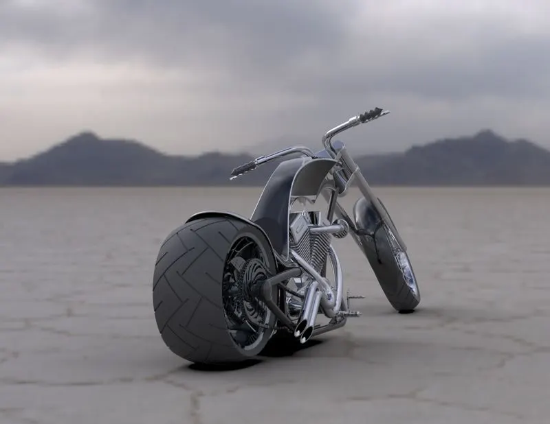
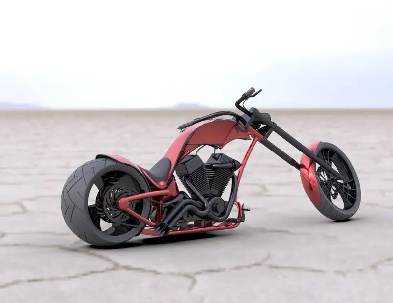
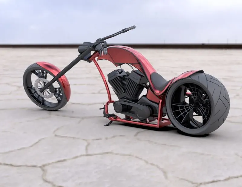
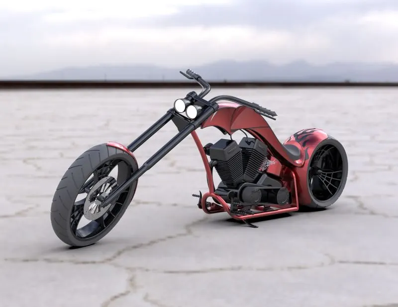
This is a technical report on the designing and rendering of American Chopper from scratch. The modelling software used is SolidWorks 2020 for sketching and modelling. For rendering SolidWorks Visualise Professional 2020 is used.
Design methodology
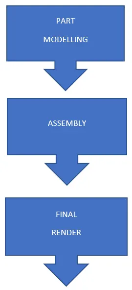
The method to carry on this project involves three major steps,
- Part modelling
- Part assembly
- Final Rendering
Part modelling
The parts of the bike to be modelled are
- Transmission belt
- Pedal
- Kickstand
- Front wheel
- Rear wheel
- Front fender
- Rear fender
- Engine
- Front fork
- Chassis
- Oil tank
- Gas tank
- Chain
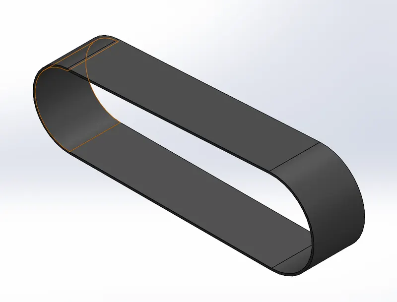
1. Transmission belt
The transmission belt is used to transmit power from one pulley to another.
Features
i. Boss extrude- extrudes a sketch from a plane in either direction to create a solid body
Tools
i. Line- used to draw straight lines and arcs.
Methodology
Sketch the straight lines and arcs using the line tool on a plane with proper dimensions. Use the offset entities from menu and extrude the sketch after getting a fully define sketch.
2. Kickstand
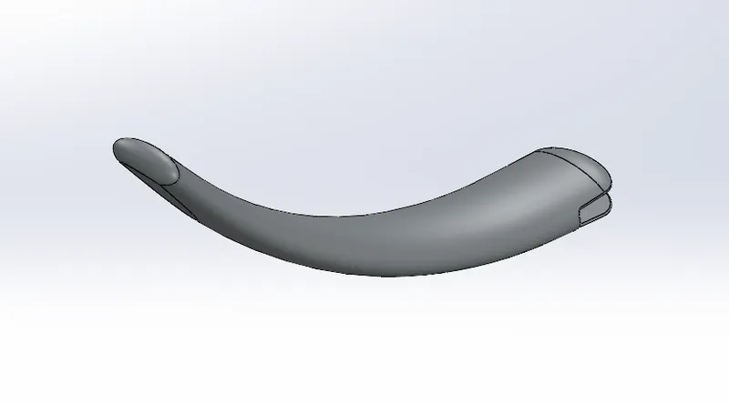
This component is used to give the bike a support when not in use by the rider.
Feature-
i. Boss extrude- extrudes a sketch from a plane in either direction to create a solid body
ii. Fillet- This feature is used to curve out sharp edges particularly for a model to look better.
iii. Lofted boss- this feature adds material between two profiles to create a solid model. The end points of the solid model are the sketch which are used.
iv. Dome- this feature adds a dome shaped solid body on the selected planar surface.
v. Split- it splits a single body into multiple bodies, in this model the body is split into two bodies where one of the body created is discarded.
Tools-
i. Circle- used to make circular sketches from the given radius or diameter.
ii. Ellipse- used to make elliptical sketches from the given dimensions.
iii. Rectangle- in this case the 'centre-point rectangle' feature is used where a rectangle is created with the reference of its midpoint.
iv. Spline- used to create splines and allows to add weight and angle dimensions.
Methodology
Sketch two ellipses as the endplanes of the kickstand using proper planes. Draw a spline between the two ellipses. Construct a lofted base between the two ellipse using the spline as the path. Add two domes at each end planes. Draw a rectangle at te larger end of the component and cut extrude, this slot facilitates the fitting of the kickstand to the chassis. Draw a circle in the slot and extrude it this cylindrical part will be rotating in the hole constructed on the chassis. Sketch a line at the smaller end of the component and use the split tool to cut a straight plane under the kickstand which will be touching the ground. Later add necessary fillet to the part.
3. Front fender
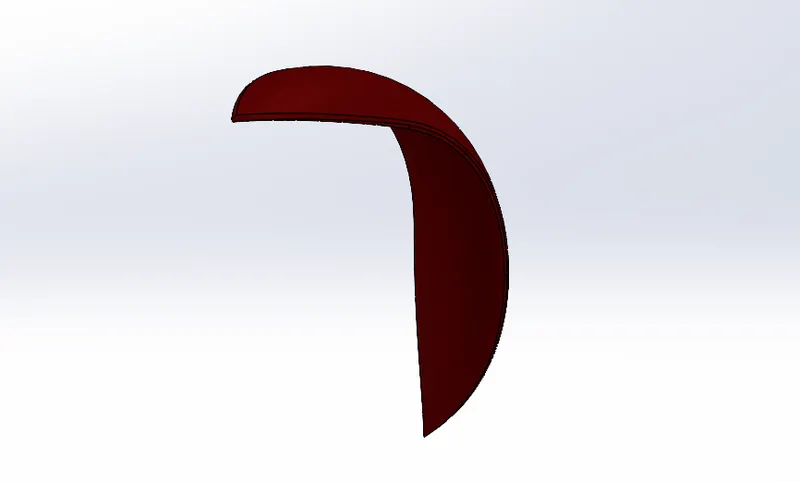
This component is used at the front wheel as a guard to the wheel. The main purpose is to avoid any small objects from the road to hit the rider or the body of the bike because of the high rotating speed of the wheel.
Feature-
i. Revolve- used to make revolve bases around an axis to create a solid body.
ii. Split- it splits a single body into multiple bodies, in this model the body is split into two bodies where one of the body created is discarded.
iii. Fillet- This feature is used to curve out sharp edges particularly for a model to look better.
iv. Extrude cut- this feature is similar to boss extrude except it creates cut instead of adding material from the sketch profile.
Tools
i. 3-point arc- used to draw arcs with a centre point reference and two extreme points reference.
ii. Spline- used to create splines and allows to add weight and angle dimensions.
iii. Dynamic mirror- used to mirror an entire feature with reference to the plane selected as the mirroring plane.
iv. Extend entities- used to extend end points of entities by some amount.
v. Trim entities- used to trim entities by some amount from their end points.
Methodology-
Used 3 point arcs to create the cross section of the component and revolve boss it. Create another sketch to create the cut at its end and cut extrude it. Dynamic mirror the cut extrude feature to achieve a proper symmetric part.
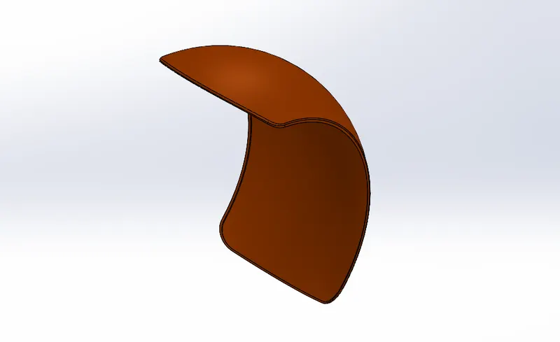
4. Rear fender
This component is used at the rear wheel as a guard to the wheel. The main purpose is to avoid any small objects from the road to hit the rider or the body of the bike because of the high rotating speed of the wheel.
Feature-
i. Revolve- used to make revolve bases around an axis to create a solid body.
ii. Split- it splits a single body into multiple bodies, in this model the body is split into two bodies where one of the body created is discarded.
iii. Fillet- This feature is used to curve out sharp edges particularly for a model to look better.
iv. Shell- used to hollow out a part and decrease wall thickness.
Tools-
i. 3-point arc- used to draw arcs with a centre point reference and two extreme points reference.
ii. Spline- used to create splines and allows to add weight and angle dimensions.
iii. Extend entities- used to extend end points of entities by some amount.
iv. Trim entities- used to trim entities by some amount from their end points.
5. Chain
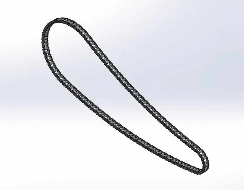
This component is used to transmit power from engine sprocket to the rear wheel sprocket in order to provide rotational movement to the wheel.
Feature-
i. Boss extrude- extrudes a sketch from a plane in either direction to create a solid body
ii. Fillet- This feature is used to curve out sharp edges particularly for a model to look better.
iii. Curve driven pattern- to create a pattern following a previously sketched curve.
Tools-
i. Circle- used to make circular sketches from the given radius or diameter.
ii. 3-point arc- used to draw arcs with a centre point reference and two extreme points reference.
iii. Blocks- creates a block folder containing a sketch which can be called in the sketch at any point of time.
iv. Trim entities- used to trim entities by some amount from their end points.
Methodology-
Sketch the chain block using circles and tangent lines. Create a 3 point arc between two adjacent chain block. Amid the process make a block of the chain sketch to call it again in future and avoid sketching all over again. Draw a curve path over which the chain blocks will be patterned. Create the chain block pins to complete all the small components used in the chain component. Use curve driven pattern to construct the entire the chain.
6. Oil Tank
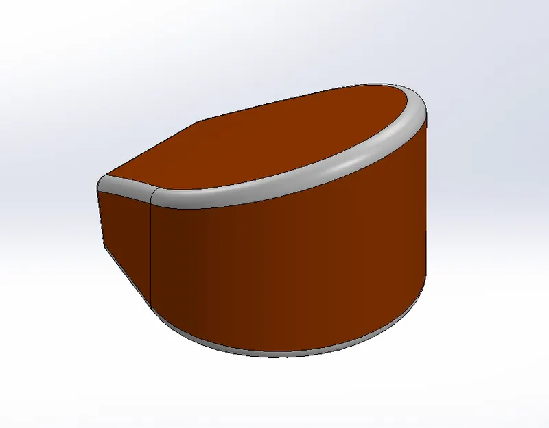
Oil tank is used to store the essential oil that is required in the proper working of the engine in the bike, the purpose is to provide lubrication between moving parts of the engine.
Features
i. Boss extrude- extrudes a sketch from a plane in either direction to create a solid body
ii. Fillet- This feature is used to curve out sharp edges particularly for a model to look better.
iii. Shell- used to hollow out a part and decrease wall thickness.
iv. Combine- used to combine two or more solid bodies into one.
Tools
i. Arc- used to draw arcs with a centre point reference.
ii. Spline- used to create splines and allows to add weight and angle dimensions.
iii. Dynamic mirror- used to mirror an entire feature with reference to the plane selected as the mirroring plane.
iv. Line- used to draw straight lines and arcs.
Methodology
Sketch the surface of the tank on the top plane and extrude it. Take the surface sketch of the side view of the tank and sketch it on the mid plane then extrude it. Choose the combine feature to combine both the solid bodies. Apply fillet to make it look aesthetic. Use the shell command to make it hollow since its a oil storage tank.
7. Pedal
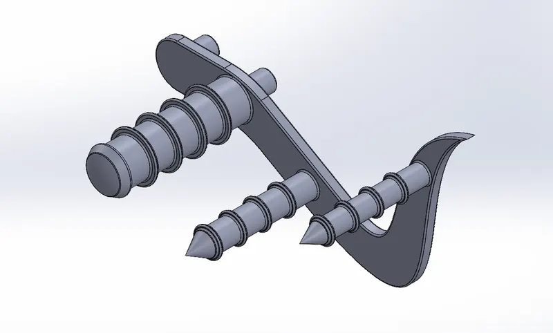
This component is used to provide foot support to the rider and also provision of brakes and gear are given to the foot pedal. Foot pedal is used to avoid road contact of the rider's foot.
Features
i. Boss extrude- extrudes a sketch from a plane in either direction to create a solid body
ii. Fillet- This feature is used to curve out sharp edges particularly for a model to look better.
iii. Revolve- used to make revolve bases around an axis to create a solid body.
iv. Dome- this feature adds a dome shaped solid body on the selected planar surface.
v. Chamfer- this feature is used to create a tapered edge on sharp edges of a solid body
vi. Linear pattern- used to pattern entities following a straight line.
vii. Fillet- This feature is used to curve out sharp edges particularly for a model to look better.
Tools
i. Line- used to draw straight lines and arcs.
ii. 3-point arc- used to draw arcs with a centre point reference and two extreme points reference.
iii. Offset- used to make a sketch parallel or concentric to the original sketch at a specified distance.
Methodology
Draw the plate part of the pedal and extrude it to the required thickness after obtaining a fully defined sketch. Sketch the required cylindrial part on the plate surface on which the foot will be resting and use the revolve and extrdue command. Draw the details of the cylindrical part and extrude it from a distance and later pattern it to make it as desired. Apply appropriate fillets and chamfer.
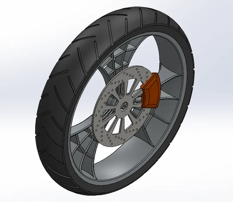
8. Front wheel
Wheel is the part of the bike which is used for the smooth motion of the bike itself. It's axis is fixed to the bike and contains a rim over which the tyre is installed.
Features
i. Fillet- This feature is used to curve out sharp edges particularly for a model to look better.
ii. Revolve base- used to make revolve bases around an axis to create a solid body.
iii. Revolve cut- used to cut in a revolve fashion around an axis to eliminate material.
iv. Chamfer- this feature is used to create a tapered edge on sharp edges of a solid body
v. Linear pattern- used to pattern entities following a straight line.
vi. Extrude cut- this feature is similar to boss extrude except it creates cut instead of adding material from the sketch profile.
vii. Circular pattern- used to create a pattern following the circumference of a circle as its path.
viii. Boss extrude- extrudes a sketch from a plane in either direction to create a solid body.
Tools
i. Line- used to draw straight lines and arcs.
ii. 3-point arc- used to draw arcs with a centre point reference and two extreme points reference.
iii. Spline- used to create splines and allows to add weight and angle dimensions.
iv. Extend entities- used to extend end points of entities by some amount.
v. Trim entities- used to trim entities by some amount from their end points.
Methodology
Sketch the cross section of the rim and revolve it after a fully defined sketch. Draw the internal part of the rim i.e. the web shaped part extrude the solid part and cut extrude what is not required. Do a circular pattern of the web shaped part around the rim.
For the rotor draw the circular disc shape and boss extrude it. Sketch the cut part of the disc and cut extrude it. Sketch the holes on the disc for the detailing and cut extrude them. Now do a circular pattern of the details around the disc.
Draw a hole right in the centre of the wheel and cut extrude it to allow the axle to be placed in it from the fork.
Sketch the caliper in the same plane as the rotor and boss extrude it. Apply appropriate chamfers and fillets to make it look like a brake caliper.
Sketch the cross section of the tyre in the similar manner as of the rim and revolve it around the rim. Now for the tire tread sketch the 2D drawing on a plane and cut extrude it from a distance to distance on the tyre and later apply a circular pattern to obtain the tire tread around the entire tyre.
9. Rear wheel
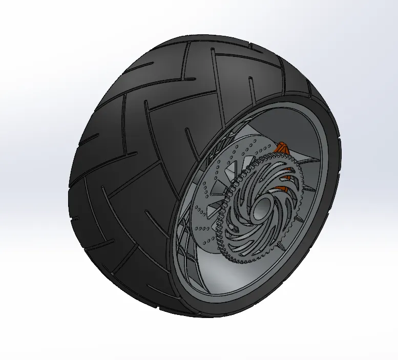
The purpose of the rear wheel is same as the front wheel. This wheel is powered by the engine.
Features
i. Fillet- This feature is used to curve out sharp edges particularly for a model to look better.
ii. Revolve base- used to make revolve bases around an axis to create a solid body.
iii. Revolve cut- used to cut in a revolve fashion around an axis to eliminate material.
iv. Chamfer- this feature is used to create a tapered edge on sharp edges of a solid body
v. Linear pattern- used to pattern entities following a straight line.
vi. Extrude cut- this feature is similar to boss extrude except it creates cut instead of adding material from the sketch profile.
vii. Circular pattern- used to create a pattern following the circumference of a circle as its path.
viii. Boss extrude- extrudes a sketch from a plane in either direction to create a solid body.
Tools
i. Line- used to draw straight lines and arcs.
ii. 3-point arc- used to draw arcs with a centre point reference and two extreme points reference.
iii. Spline- used to create splines and allows to add weight and angle dimensions.
iv. Extend entities- used to extend end points of entities by some amount.
v. Trim entities- used to trim entities by some amount from their end points.
Methodology
Sketch the cross section of the rim and revolve it after a fully defined sketch. Draw the internal part of the rim i.e. the web shaped part extrude the solid part and cut extrude what is not required. Do a circular pattern of the web shaped part around the rim.
For the rotor draw the circular disc shape and boss extrude it. Sketch the cut part of the disc and cut extrude it. Sketch the holes on the disc for the detailing and cut extrude them. Now do a circular pattern of the details around the disc.
Draw a hole right in the centre of the wheel and cut extrude it to allow the axle to be placed in it from the fork.
Sketch the caliper in the same plane as the rotor and boss extrude it. Apply appropriate chamfers and fillets to make it look like a brake caliper.
Sketch the cross section of the tyre in the similar manner as of the rim and revolve it around the rim. Now for the tire tread sketch the 2D drawing on a plane and cut extrude it from a distance to distance on the tyre and later apply a circular pattern to obtain the tire tread around the entire tyre.
For the sprocket, sketch the circular disc shape on a plane and extrude boss it. On any part of the disc draw the teeth of the sprocket on the edge of the disc and cut extrude it. Do a circular pattern of the cut extrude to obtain a set of teeth around the disc. Draw the details of the sprocket on its side, cut extrude it and apply a circular pattern.
10. Front Fork
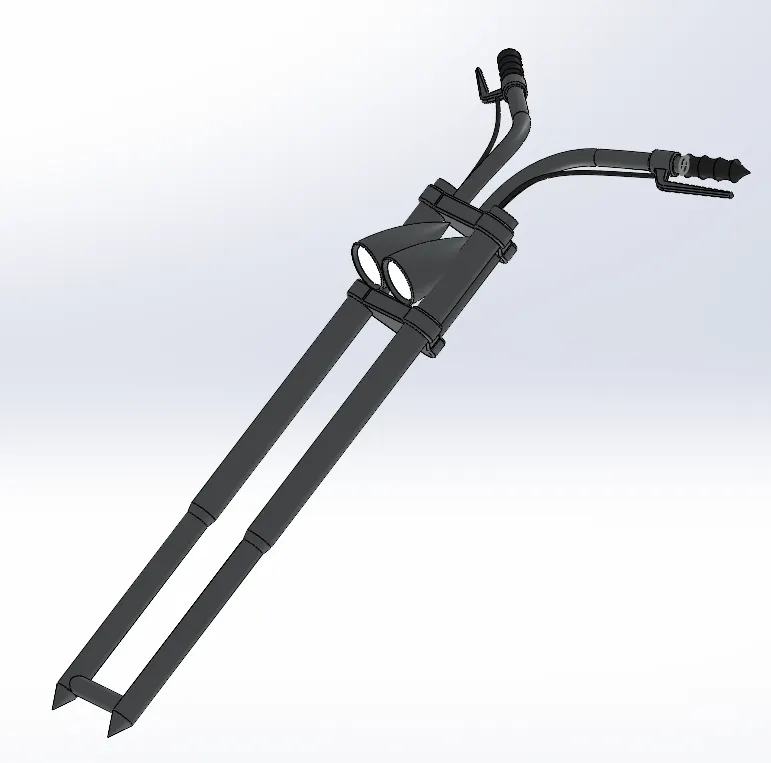
The front fork carries the two shock absorber, the axle of the front wheel, handle bar for changing directions and the headlights.
Feature
i. Revolve base- used to make revolve bases around an axis to create a solid body.
ii. Boss extrude- extrudes a sketch from a plane in either direction to create a solid body.
iii. Dome- this feature adds a dome shaped solid body on the selected planar surface.
iv. Combine- used to combine two or more solid bodies into one.
v. Split- it splits a single body into multiple bodies, in this model the body is split into two bodies where one of the body created is discarded.
vi. Move-Copy Body- used to move or copy a whole solid body to a new place.
vii. Mirror- used to mirror a whole solid body with a mirror reference such as a plane.
viii. Sweep- used to sweep a closed profile along an open or closed path to create a solid body.
Tools
i. Projected curve- This tool is very useful in terms of making a comlex curve that does not used a single plane to move along. This tool helps integrate two curves from different planes resulting in the desired complex single curve.
ii. Convert entities- converts selected edges adn sketch entities into by projecting them onto the current sketch plane or surface.
iii. Line- used to draw straight lines and arcs.
iv. 3-point arc- used to draw arcs with a centre point reference and two extreme points reference.
v. Spline- used to create splines and allows to add weight and angle dimensions.
Methodology
Revolve the long cylindrical fork on one side after getting a fully defined sketch of its half cross section. Sketch the base where the handle bars are going to rest and extrude it. Do a linear pattern of that base and add another one below it. Between these two bases will lie the headlights of the bike.
Sketch the axle at the side of that one fork and extrude it to the required appropriate length. Connect the two bases above with another cylindrical contour.
Sketch one headlight on a plane and revolve it. Now move the headlight to its appropriate place to facilitate another headlight in the given space.
Use projected curves and sweep tools to construct the handle bars and the brake wires.
Now mirror the components that are needed to on the other side of the mirror plane such as the fork, handle bars, brakes and wires.
Combine the solid bodies accordingly.
11. Chassis
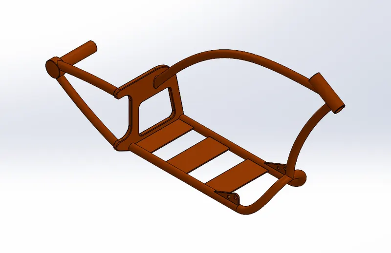
This part of the bike is the skeleton on which all the parts rest. The chassis acts as the mainframe which carries each part from the fork and wheels to the engine.
Features
i. Mirror- used to mirror a whole solid body with a mirror reference such as a plane.
ii. Sweep- used to sweep a closed profile along an open or closed path to create a solid body.
iii. Boss extrude- extrudes a sketch from a plane in either direction to create a solid body.
iv. Dome- this feature adds a dome shaped solid body on the selected planar surface.
v. Combine- used to combine two or more solid bodies into one.
vi. Split- it splits a single body into multiple bodies, in this model the body is split into two bodies where one of the body created is discarded..
vii. Fillet- This feature is used to curve out sharp edges particularly for a model to look better.
viii. Chamfer- this feature is used to create a tapered edge on sharp edges of a solid body
ix. Revolve base- used to make revolve bases around an axis to create a solid body.
Tools
i. Projected curve- This tool is very useful in terms of making a comlex curve that does not used a single plane to move along. This tool helps integrate two curves from different planes resulting in the desired complex single curve.
ii. Convert entities- converts selected edges adn sketch entities into by projecting them onto the current sketch plane or surface.
iii. Line- used to draw straight lines and arcs.
iv. Spline- used to create splines and allows to add weight and angle dimensions.
v. Circle- used to make circular sketches from the given radius or diameter.
Methodology
For this component we need a reference or a blue print of the bike to sketch along the picture and make our job easier. Using the sketch picture command and placing it appropriately then using the various tools such as line, spline, projected curve, sweep etc.
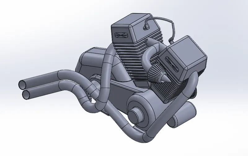
12. Engine
Engine is power generating component of any vehicle. It takes fuel as its input and gives rotational movement as its output which is transmitted to the rear wheel via sprocket and chain arrangement.
Features
i. Mirror- used to mirror a whole solid body with a mirror reference such as a plane.
ii. Sweep- used to sweep a closed profile along an open or closed path to create a solid body.
iii. Boss extrude- extrudes a sketch from a plane in either direction to create a solid body.
iv. Dome- this feature adds a dome shaped solid body on the selected planar surface.
v. Combine- used to combine two or more solid bodies into one.
vi. Split- it splits a single body into multiple bodies, in this model the body is split into two bodies where one of the body created is discarded..
vii. Fillet- This feature is used to curve out sharp edges particularly for a model to look better.
viii. Revolve base- used to make revolve bases around an axis to create a solid body.
ix. Chamfer- this feature is used to create a tapered edge on sharp edges of a solid body
x. Linear pattern- used to pattern entities following a straight line.
xi. Circular pattern- used to create a pattern following the circumference of a circle as its path.
Tools
i. Projected curve- This tool is very useful in terms of making a comlex curve that does not used a single plane to move along. This tool helps integrate two curves from different planes resulting in the desired complex single curve.
ii. Convert entities- converts selected edges adn sketch entities into by projecting them onto the current sketch plane or surface.
iii. Line- used to draw straight lines and arcs.
iv. 3-point arc- used to draw arcs with a centre point reference and two extreme points reference.
v. Trim entities- used to trim entities by some amount from their end points.
vi. Offset- used to make a sketch parallel or concentric to the original sketch at a specified distance.
vii. Composite curve- combines selected curves and edges into a single curve.
Methodology
Just like the chassis we will require the blueprint sketch picture for the engine.
Sketch the base or the foundation of the engine over which the various components are going to rest and boss extrude it.
Sketch both the pulleys over which the transmission belt is going to operate and revolve it. Construct the teeth details on the pulleys.
Construct one of the engine blocks and mirror this to obtain two of them.
Create the sprocket which will be used to transmit the power to the rear wheel sprocket via chain.
Create the tubes for the air intake by constructing curves and sweeping the contour along them.
Construct the exhausts and spark plug cable using the projected curve option. Use the split command to give the final touch to the tip of the exhausts.
13. Gas Tank
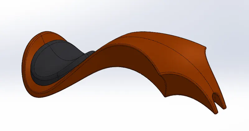
This is the fuel storing component of the bike which supplies to the engine to power it up when needed.
Features
i. Swept surface- used to make surfaces along a curve as its path.
ii. Boundary surface- used to create a surface between profiles that can be tangent or continuous curvature.
iii. Loft surface- used to create lofts between two or more profiles or sketches.
iv. Knit surface- Combines two or more adjacent, non-intersecting surfaces into a single body.
v. Swept cut- used to cut a solid model by sweeping along the defined path contrary to sweep which adds material.
vi. Combine- used to combine two or more solid bodies into one.
vii. Shell- used to hollow out a part and decrease wall thickness.
viii. Fillet- This feature is used to curve out sharp edges particularly for a model to look better.
Tools
i. Projected curve- This tool is very useful in terms of making a comlex curve that does not used a single plane to move along. This tool helps integrate two curves from different planes resulting in the desired complex single curve.
ii. Convert entities- converts selected edges adn sketch entities into by projecting them onto the current sketch plane or surface.
iii. Line- used to draw straight lines and arcs.
iv. 3-point arc- used to draw arcs with a centre point reference and two extreme points reference.
v. Mirror- used to mirror a whole solid body with a mirror reference such as a plane.
Methodology
First bring in the blue print sketch picture to make sure the outline of the gas tank is proper. Draw the required splines and sweep it appropriately.
Use projected curves to extrude loft surface using guided curve and complete the solid body of the tank.
Now use the shell feature to make the tank hollow since it is a storage to fuel.
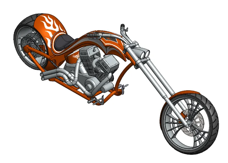
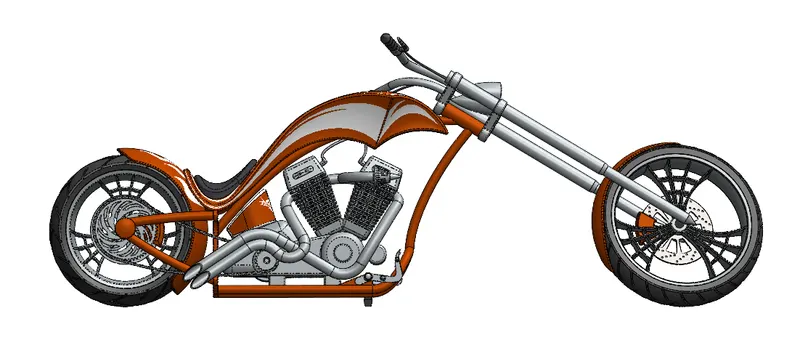
Assembly of American Chopper
In this part we will be assembling all the part components modelled in the solidworks assmeblt environment
For this we will insert all the part documents in the assembly.
Mates- This is the essential feature of assembling the parts of the bike. Mates helps us to obtain a accurate assembly of the parts without any gaps or misalignments by calling in appropriate relations between the part surfaces and edges.
Types of mates-
i. Advanced mates
ii. Mechanical mates
Now apply the decals after the assembly is complete.
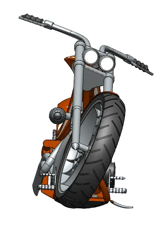
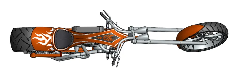
The camera view-
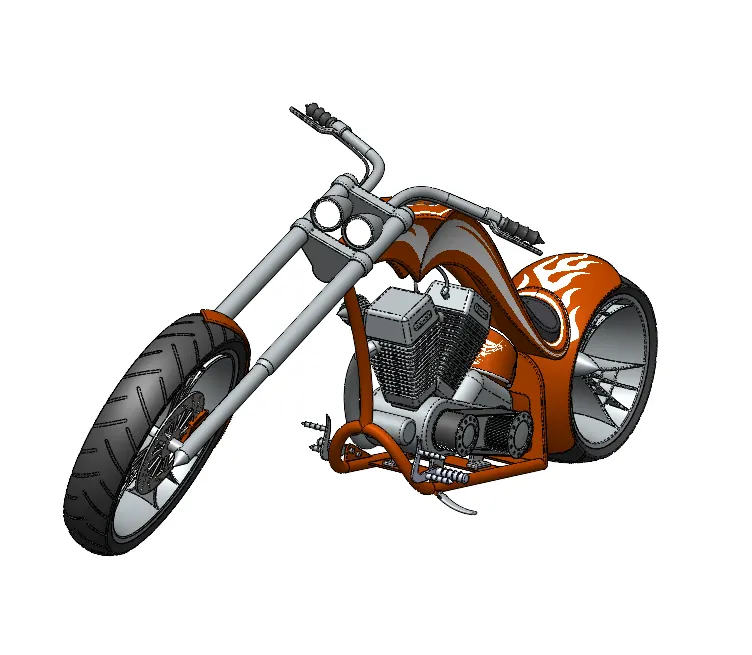
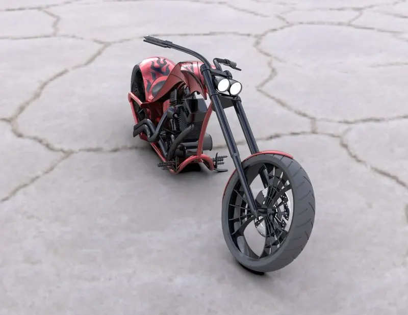
Render
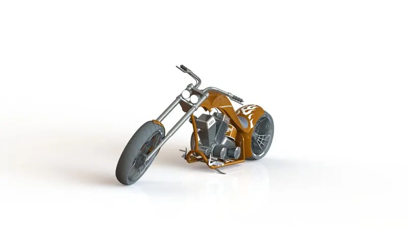
This is the process of making the model look real in a photo realistic environment using SolidWorks Visualize.
Features-
i. Environment
ii. Backplate
iii. Brightness, gamma exposure, etc.
iv. Colour, material, texture etc of the model
Conclusion
i. We understood the steps to carry on for part modelling and most importantly parametric relation which helps in applying appropriate relations to various components within the part.
ii. A good understanding of assembly of the part documents and the various ways to apply mates. Steps to edit a part due to a mismatch during assembly was also understood.
iii. Practised to make the model look aesthetically good by applying decals, lights, environment, appearances, etc. using SolidWorks, Photoview360 and SolidWorks Visualize.