Photo Realistic Rendering
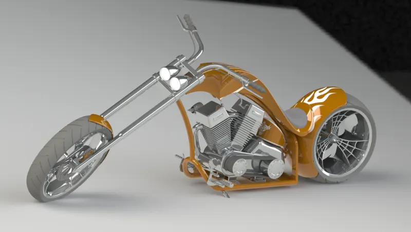
MODELLING AN AMERICAN CHOPPER USING SOLIDWORKS
1.Objective
- The objective of this product is to model the American Chopper Bike and to learn how to use the SOLIDWORKS software.
- And use Photo View 320 to render the chopper to give it a realistic look and feel (Visualize 360 was not available with Solidworks)
- Introduction
The design of this American chopper involves modelling of various parts and the create an assembly of them with proper alignment.
These parts include
Chassis
- Engine
- Kickstand
- Pedal
- Transmission belt
- . Oil tank
- Rear Wheel
- Rear Fender
- Chain
- Gas Tank
- Front Fork
- Front Wheel
- Front Fender
3.Approach To Design
The design of the bike is done by following steps:
- To design all the parts of the bike.
- To assemble all the modeled parts.
- To create camera set up light settings etc.
- To do the rendering of the bike using photoview 360.
MODELLING OF THE PARTS WAS DONE USING FEATURES LIKE
1. 2D-Sketches: This feature helps you create any geometry which is 2D and the
created 2D geometry can be controlled by applying relations and these
sketches can be modifies using various sketch tools.
2. Boss Extrude: This feature allows us to take our 2D sketch and convert it into
a 3D solid body by adding a third dimension of height/thickness to it.
3. Revolved Boss: This feature allows us to create a 3d object about an axis to
create a solid body.
4. Sweep: This feature creates a base, boss, cut, or surface by moving a profile
(section) along a path
7. Offset: This feature helps us offset the selected sketch entities by a given
distance.
8. Convert entities: This helps us convert the edges or faces of a 3d model to a
2d sketch for our further use.
9. Loft: This feature helps us create a transition between profiles.
10.Dome: This feature helps us create a dome like structure on the selected faces of
the sketch
11. Fillet: This feature helps us create an external or internal rounded part on the
component.
12. Knit: This feature helps us combine two or more faces and surfaces into one.
13. Combine: This feature helps us combine two or more solid bodies into one.
14.Shells: This feature helps us create a hollow part out of a solid body.
15. Surface Trim: This helps us remove the unwanted material of the surface.
16. Split: The Split Line tool projects an entity to surfaces, or curved or planar faces. It divides a selected
face into multiple separate faces.
17. Chamfer: This feature helps us creates a beveled feature on selected edges,
faces,
or a vertex.
MODELLING OF VARIOUS PARTS IS DONE AS FOLLOWS
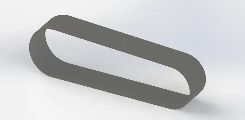
Transmission Belt:
For designing this Belt , sketch thediagram of the belt and extruding the sketch using the option available Boss Extrude option present in features tab.
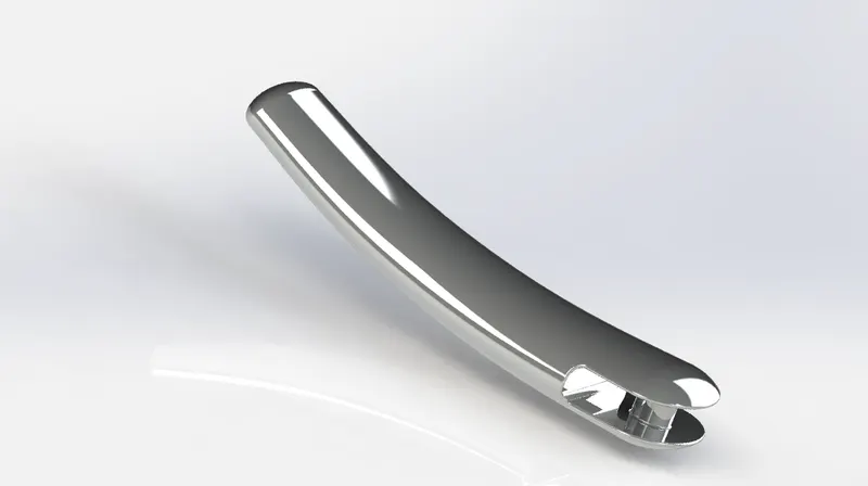
Kick Stand:
The design of kick stand is made by using the Loft option.Here we also use the Dome option to create a dome type ends.
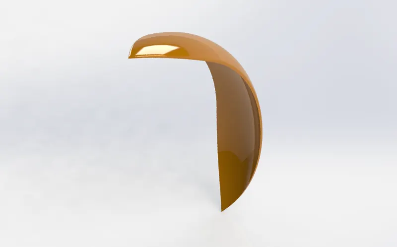
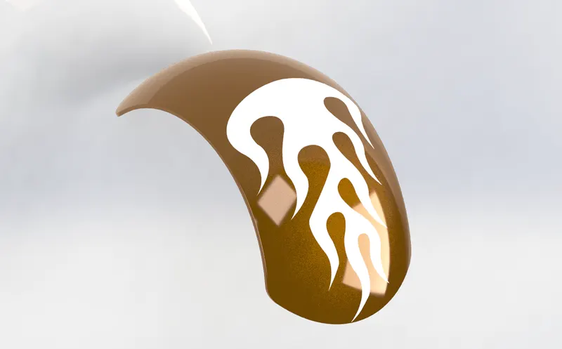
Front Fender And Rear Fender
Fenders are designed using simple sketch which is converted to solid 3d object by using the Revolve option available at feature tab which helps to create a circular object for a required angle.
All the sharp edges are made curved using the fillet option.
Split option which is used to split and remove the unwanted material from the final object
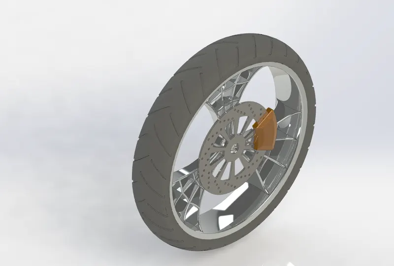
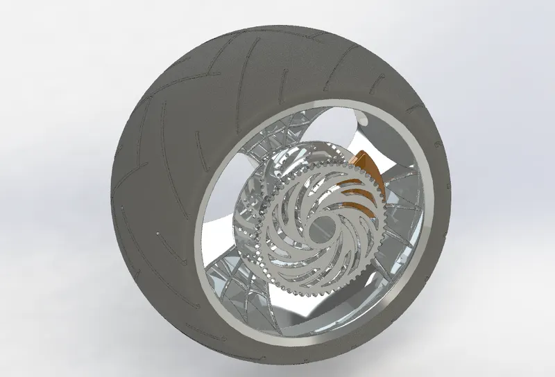
Wheels
Wheels are designed using options like Boss extrude, well as circular patter top create the rims , Cut Extrude which helps top remove the sketched material.Revolve is also used Fillets are used to prepare the edges.
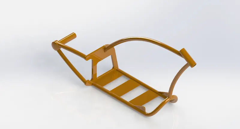
Chassis
Chassis is designed with the help of simple sketch made using on different planes and are extruded using the sweep to create hallow tube like structure individually and combining them to form a single solid .
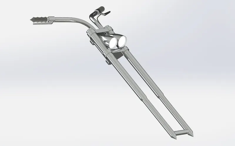
Front Fork
Designing this model involved with bose exrtude, swept bosebase and variors extude features.
Engine
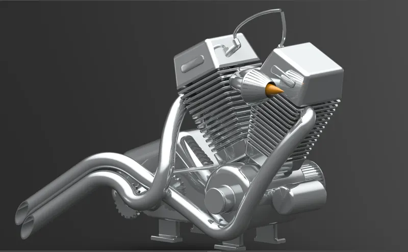
This Design involves several sketches on different . Features like Bosslextrude, cut extrude, mirror, pattern, sweep. Specially for creating the exhaust vents we use composite curve option which is used to create a curve where the two curve extrudes from 2 different planes meet.nad that joint forms as another curve to form a single curve.(Engine was rendered using photoview 360)
Gas Tank And Oil Tank
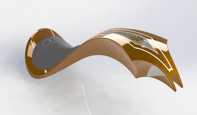
The design of gas tank model involves various options like surface loft, surface sweep, surface extrude surface knit, which helps to develop a hallow tank as shown in figure.
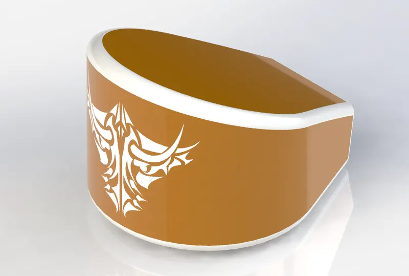
The Oil Tank uses a simple extrude feature along with shell feature and a few fillets.
Pedal
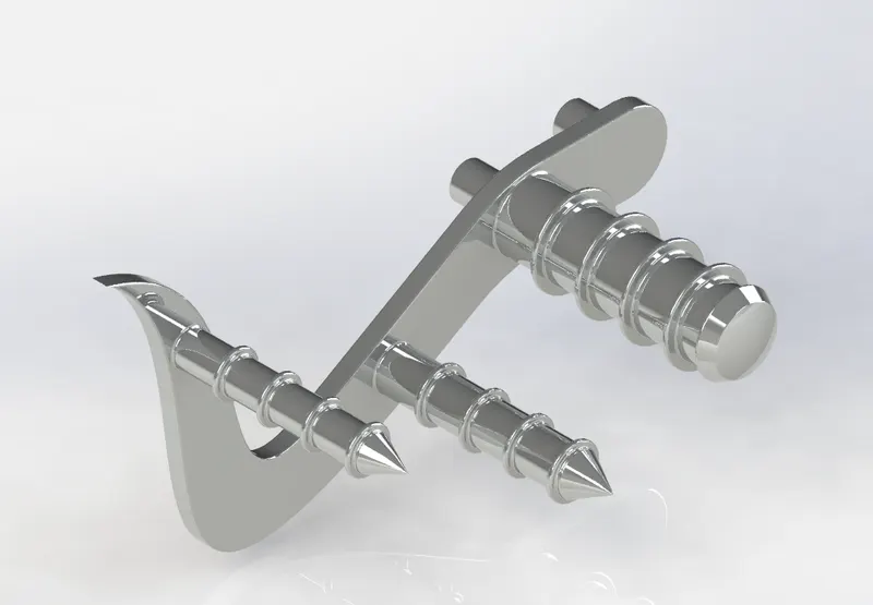
This model was designed with spline feature for 2d sketch , linear patterns , bose extrude and revolve features are used for creating the 3d model.
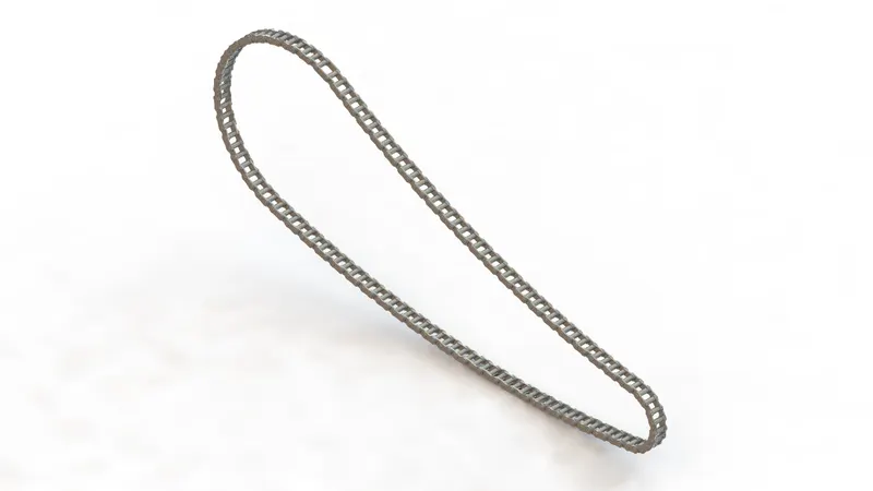
Chain
For this model, 2d slot blocks to create chain slots were created which were later merged with several other slots using extrude feature to interlock and create the chain which was then joined by an extrude feature.
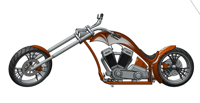
ASSEMBLY'
All the above parts mentioned are then assembled with proper mate features, joints and limitations to create a perfectly modelled American Chopper.
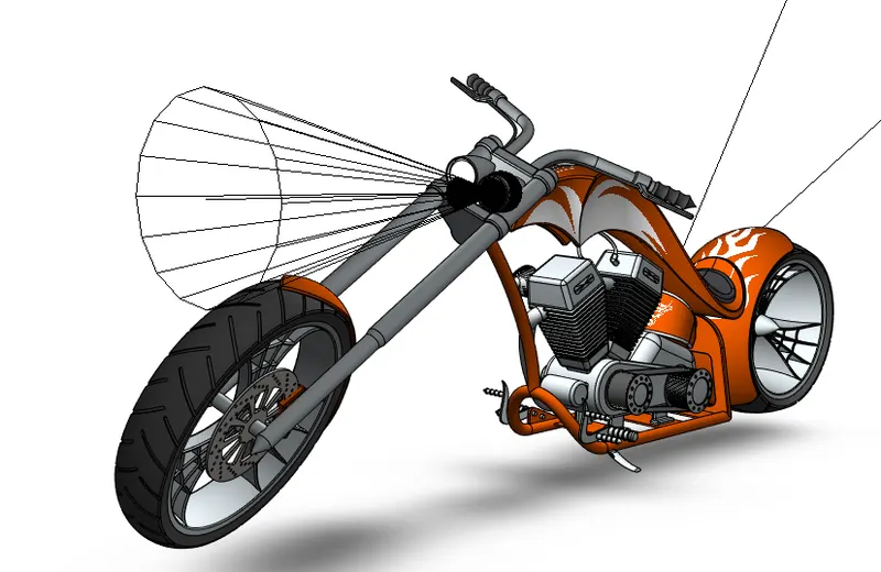
Camera and LightsSetup:
The camera setup can be found in insert>view>lights and Camera so that the chopper can appear to look much more prettier and cinematic.
T he lights are also setup as you can see near the headlamps of the motorcycle.
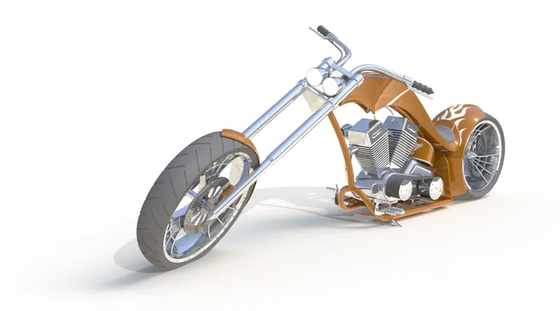
RENDERING
ALL THE RENDERS WERE DONE IN PHOTOVIEW 360 AS VISUALIZE WASNT AVAILABLE.
ISOMETRIC VIEW
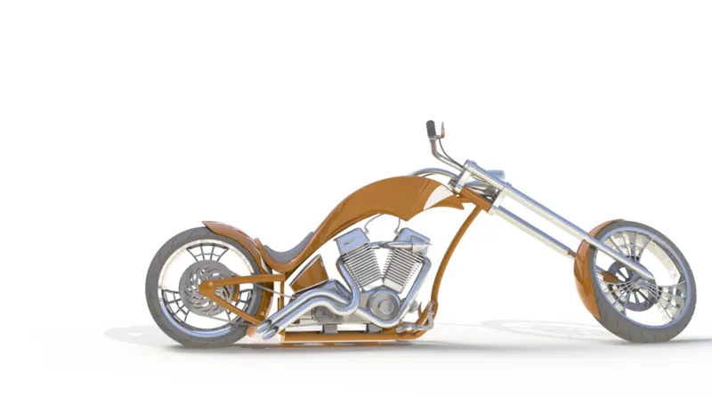
SIDE VIEW
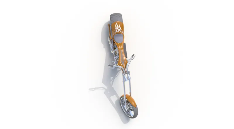
TOP VIEW
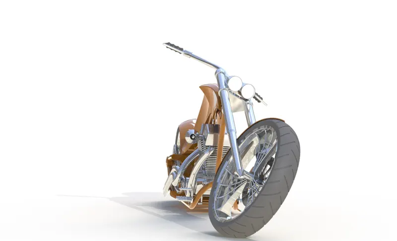
FRONT VIEW
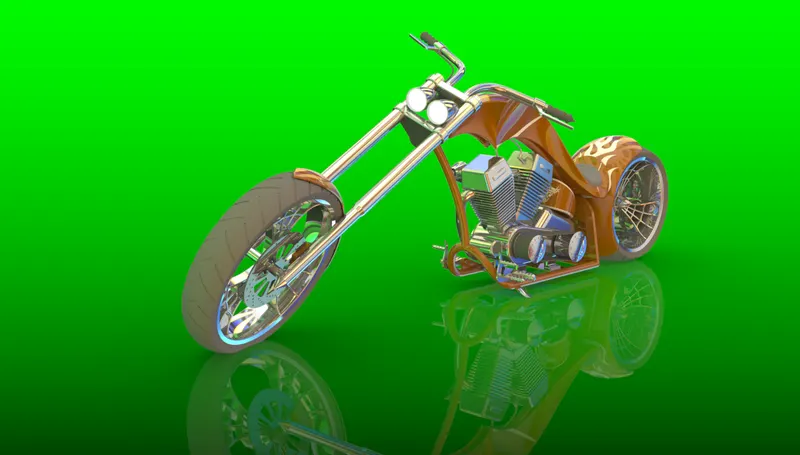
USING SEVERAL BACKGROUNDs
CONCLUSION
Finally we are done with the model and its renders.
This project was interesting and very fun to work on.
I have learnt alot about sevveral features in solidworks just by working on this project.