Flow over an airfoil
FLOW SIMULATION OVER A NACA0017 AIRFOIL
Using Solidworks
AIM: To simulate flow over a NACA00017 airfoil at different angle of attacks to compare lift and drag forces
OBJECTIVE:
- To model a NACA0017 airfoil using solidworks
- To Setup The input parameters and output times in the Wizard
- To set various Goals and Refine mesh conditions
- To Run the simulation in 2D and
- To compare its Lift and Drag Forces at Angle Of Attacks at 0,2,4,6,8,10
OVERVIEW:
Airfoil
An Airfoil, also spelled Aerofoil, shaped surface, such as an airplane wing, tail, or propeller blade, that produces lift and drag when moved through the air. An airfoil produces a lifting force that acts at right angles to the airstream and a dragging force that acts in the same direction as the airstream
An airplane's wing has a special shape called an airfoil. The airfoil is shaped so that the air traveling over the top of the wing travels farther and faster than the air traveling below the wing. Thus, the faster moving air above the wing exerts less pressure than the slower moving air below the wing.
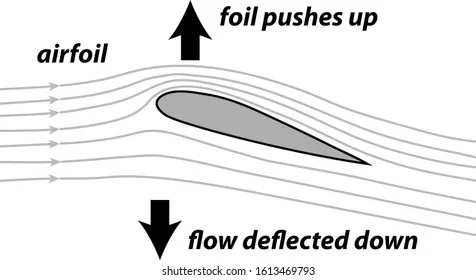
NACA0017 Airfoil
The NACA airfoil section is created from a camber line and a thickness distribution plotted perpendicular to the camber line.The equation for the camber line is split into sections either side of the point of maximum camber position (P).
This NACA airfoil series is controlled by 4 digits : NACA MPXX
- M is the maximum camber divided by 100. In the example M=2 so the camber is 0.02 or 2% of the chord
- P is the position of the maximum camber divided by 10. In the example P=4 so the maximum camber is at 0.4 or 40% of the chord.
- XX is the thickness divided by 100. In the example XX=12 so the thiickness is 0.12 or 12% of the chord.
Angle Of Attack
Angle of attack is the angle between the body's reference line and the oncoming flow. In aerodynamics, angle of attack specifies the angle between the chord line of the wing of a fixed-wing aircraft and the vector representing the relative motion between the aircraft and the atmosphere.
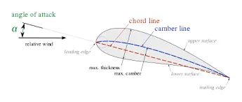
Lift Force
Lift force is basically defined as the force exerted on the body in a direction perpendicular to the direction of motion when fluid is moving and body is stationary or body is moving and fluid is stationary. Lift force will be represented by the symbol F L.
Drag Force
force exerted by a fluid stream on any obstacle in its path or felt by an object moving through a fluid. Its magnitude and how it may be reduced are important to designers of moving vehicles, ships, suspension bridges, cooling towers, and other structures.
NACA0017 Airfoil Model
1.To model NACA0017 airfoil, it is required to download its data file from NACA airfoil website and later paste it in Insert Curve Option.
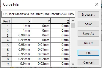
2.Solideworks will then perfrom calculations and automatically draw the curve for you.
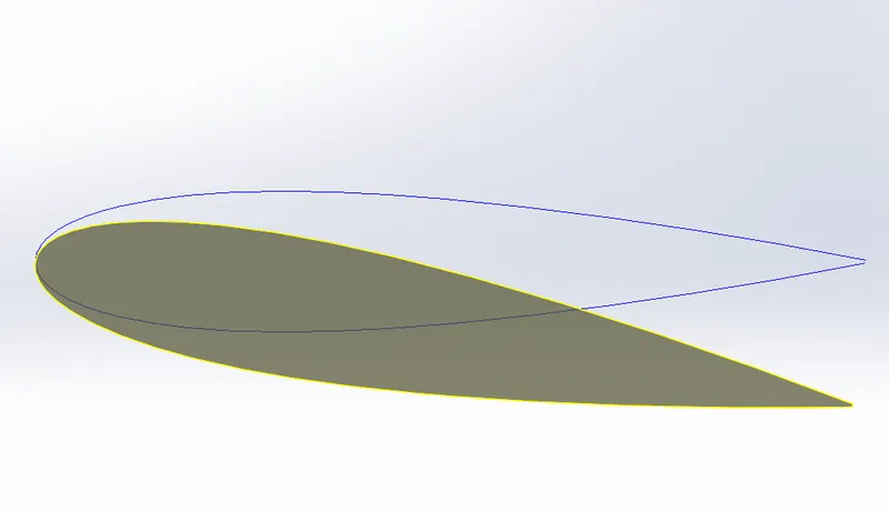
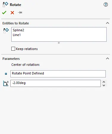
3.Once the curve is made , the origin is taken as the point of rotation and different angles of Attack can be taken as input by setting the angle of rotation in this case it is 10 degrees. This can be done in Rotate Entities Option in Move Entities Tab.
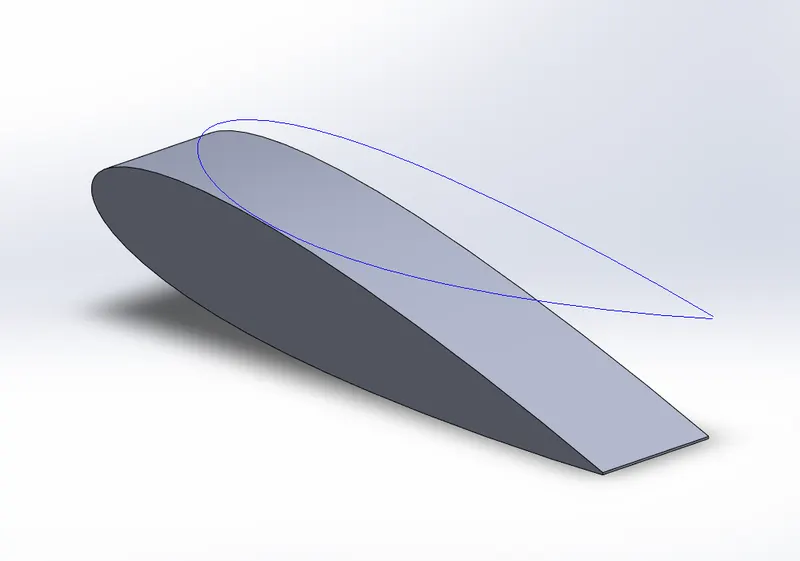
4.Then the curve is extruded at 0.195mm to finally create the airfoil.
PROCEDURE:
1. Once the foil is created, go to Flow Simulations and input the parameters and Output times in the Wizard.
Analysis Menu
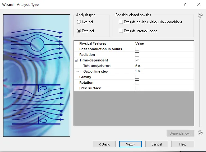
Total Time = 5 seconds
Output Time = 1 second
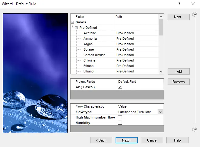
Fluid Type
Velocity in X Direction
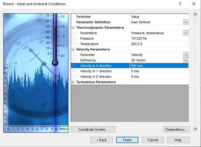
Velocity in X direction taken as 600m/s
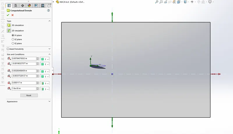
2. Set the Computational Domain to 2D and enlarge it so that the outflow boundary is sufficiently placed.
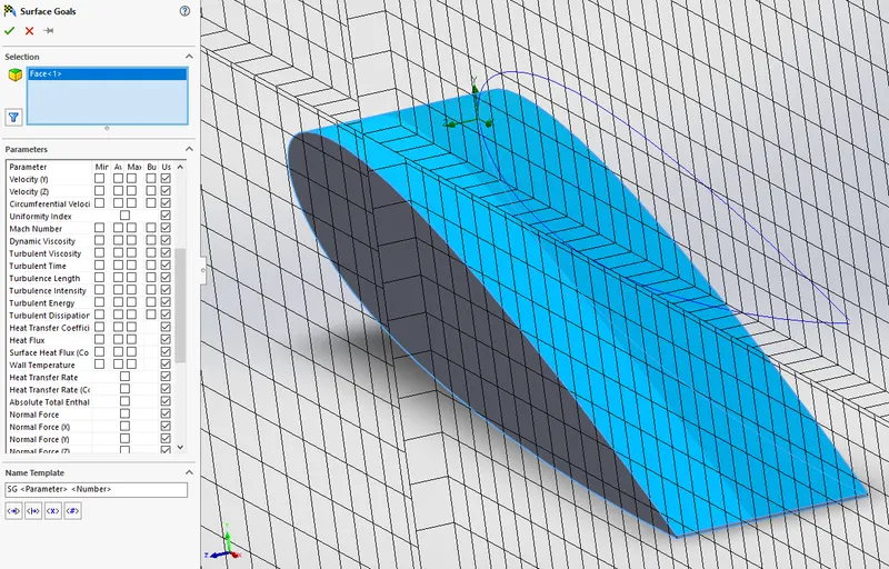
3. Setup Various Global and Surface Goals across the Curved face of the foil.
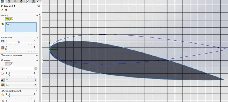
4.Set Mesh Refinement level to 4 across the curved surface of the foil.
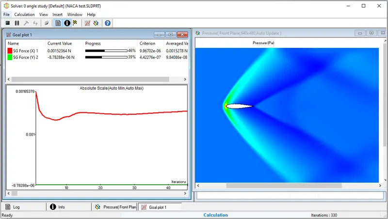
5. Run The Simulation and observe the results.
Solver Display
6. Repeat this process for different angle of attacks.
RESULTS
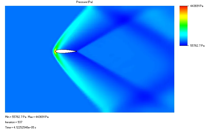
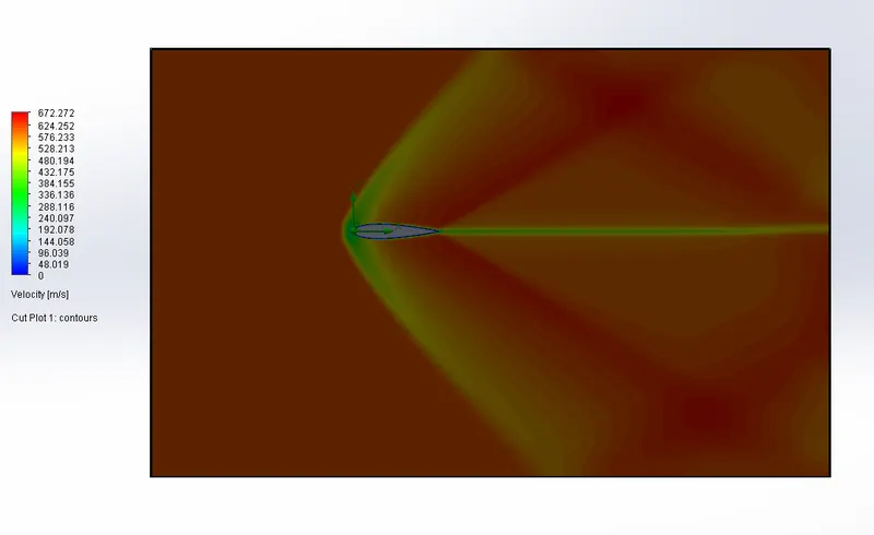
1. Angle Of Attack at 0 degrees
Pressure Plot
Velocity Plot
To compare its Lift and Drag Forces

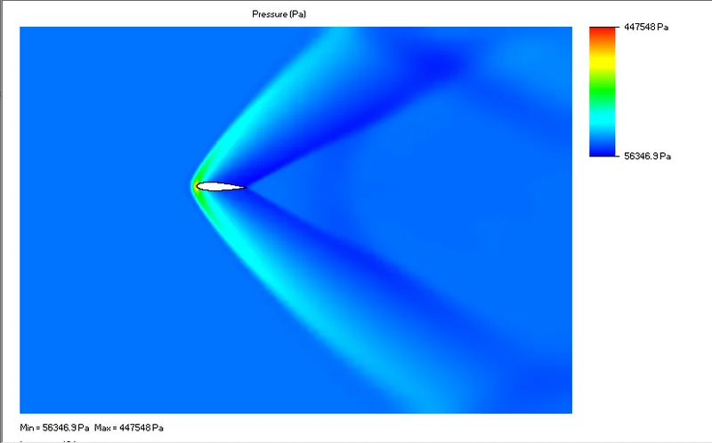
2. Angle Of Attack at 2 degrees
Pressure Plot
Velocity Plot
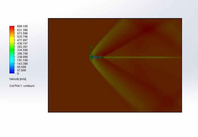
To compare its Lift and Drag Forces

3. Angle Of Attack at 4 degrees
Pressure Plot
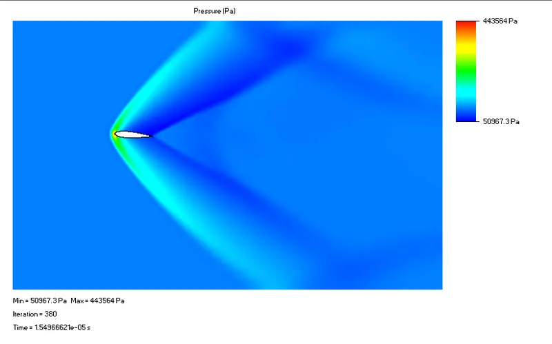
Velocity Plot
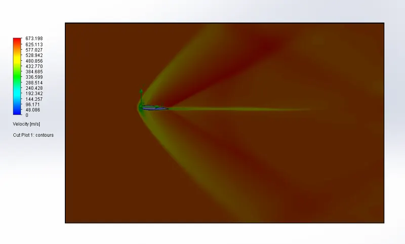
To compare its Lift and Drag Forces

4. Angle Of Attack at 6 degrees
Pressure Plot
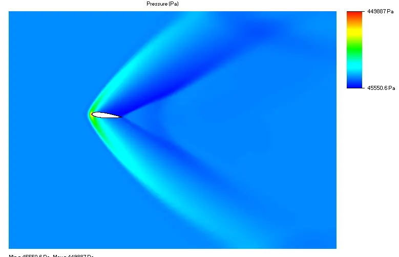
Velocity Plot
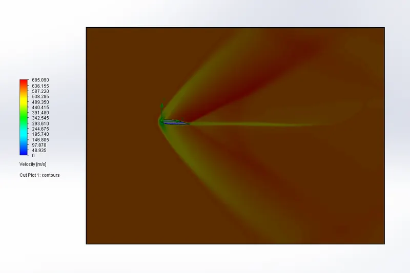
To compare its Lift and Drag Forces

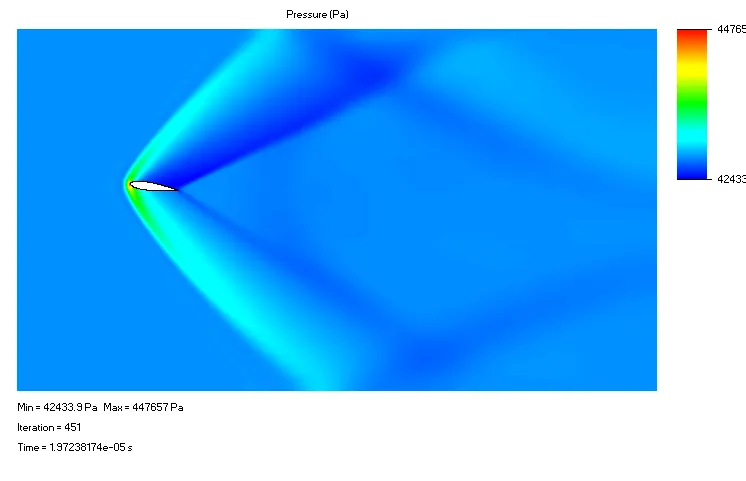
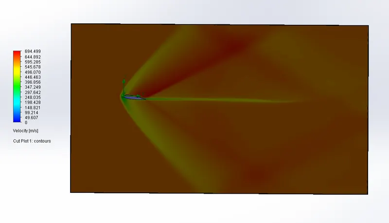
5. Angle Of Attack at 8 degrees
Pressure Plot
Velocity Plot
To compare its Lift and Drag Forces
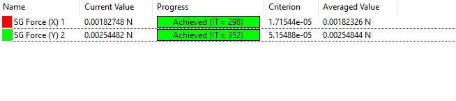
6. Angle Of Attack at 10 degrees
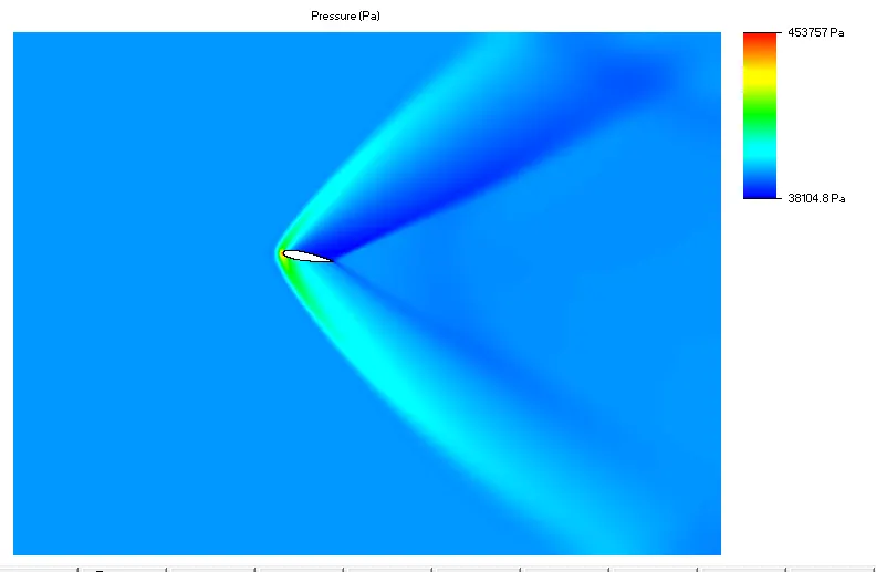
Pressure Plot
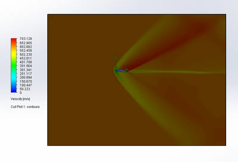
Velocity Plot
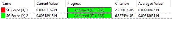
To compare its Lift and Drag Forces
Observation and Conclusion:
- The lift force increases with increase in the angle of attack, this is due to increase in pressure difference between the bottom and top part of the airfoil.
- The drag force remains almost constant till 4 degrees angle of attack, but increases further increase due tochange in the frontal area.