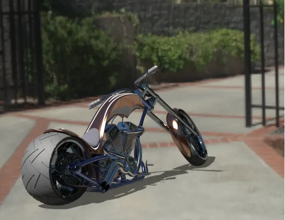
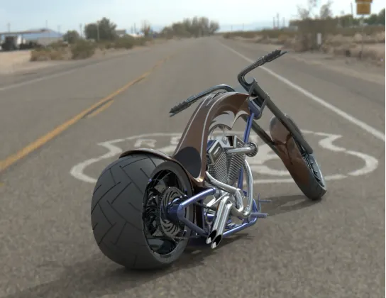
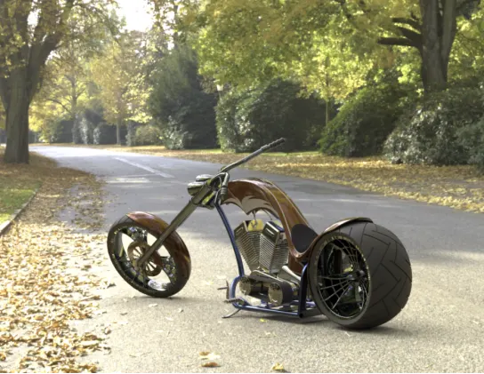
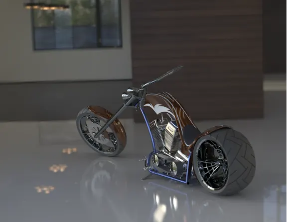
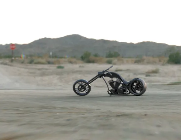
Photo Realistic Rendering
MODELLING OF CHOPPER IN SOLIDWORKS
INTRODUCTION
The SOLIDWORKS Software
The SOLIDWORKS® CAD software is a mechanical design automation application that lets designers quickly sketch out ideas, experiment with features and dimensions, and produce models and detailed drawings. This document discusses concepts and terminology used throughout the SOLIDWORKS application to produce a roughly 1980’s based Chopper and set it up in an environment.
It familiarizes with the commonly used functions of SOLIDWORKS.
In this report, concepts and design processes in a high-level approach are introduced.
Firstly the 2D sketches are designed on different planes, followed by a step by step approach to enhancing these sketches to a full-fledged 3D model as per the specified dimensions, thus completing the part.
This method is used to make several parts of the Chopper and finally complete the assembly of the Chopper by fixing the individual parts mainly using the “Mate” option as well as considering the orientation and angles, thereby specifying the type of material and colour as we progress.
The assembly in then set up in an environment and rendered to get a high quality image using SolidWorksVisualize software.
SolidWorks provides a plethora of tools to a designer to work and use as per needs of the design requirements.
The design approach is understood and also the tools and features used along the making of the model is considered in this report.
The models are made as per the functionality of individual parts to obtain results close to real life situations, finally producing the rendered images after setting up the Chopper Assembly in a predefined SolidWorks Environment.
Components that are designed using SolidWorks are:
Transmission Belt
Kickstand
Front Fender
Rear Fender
Chain
Oil Tank
Pedal
Front wheel
Rear Wheel
Front Fork
Chassis
Engine
Gas Tank
Assembly
OBJECTIVE
- To learn SolidWorks commands
- Design of all parts of Chopper with help of a blueprint sketch to fit dimensions
- Assembly of individual parts
- Understand basic features of setting up views, appearance, material of parts/components and adjusting according to desirability
- Trial and error methods and hunt for score of improvements using photoview 360
- Rendering high quality image using SoliodWorksVisualize
DESIGN PROCESS
The design process usually involves the following steps:
- Identify the model requirements.
- Conceptualize the model based on the identified needs.
- Develop the model based on the concepts.
- Analyze the model.
- Prototype the model.
- Construct the model.
- Edit the model, if needed.
DESIGN APPROACH METHODOLOGY
To perform a design, a designer can choose one of the two ways of broadly classified approaches. They are
1) Top-Down Approach or the In-Context Design
This approach is often used, when the product being designed is large that it requires many further sub-parts to complete the design. A senior-level designer might create the initial assembly layout, then divide the assembly layout into logical sub-assemblies and parts for the remainder of the organization to complete.
It is an assembly centric modelling method.
- Bottoms-Up Approach
the assembly design is started with a principal structural or functional element, and individual parts are designed in relative isolation from the overall assembly. Component parts and sub-assemblies are defined as the process moves up towards the top-level assembly.
It is a part centric modelling method.
|
|
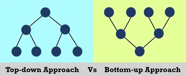
For the modelling of the Chopper, we use the Bottoms-Up Approach.
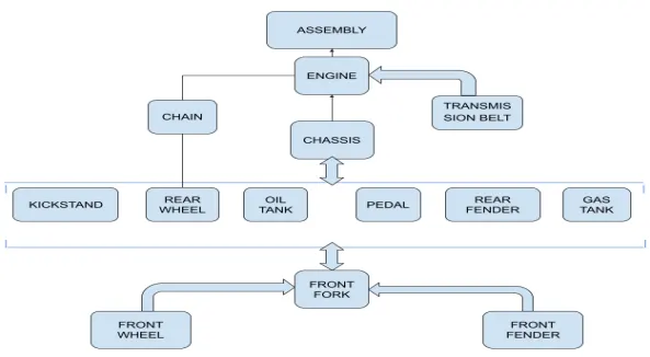
We make individual parts (engine consisting of fins, exhaust system,etc, the front fork, chain, pedal, gas tank) and build our way through to complete a component mounting it on chassis, thereby completing the assembly.
SOLIDWORKS TOOLS/FEATURES USED
- Extrude Boss/Cut
- Fillet
- Revolve boss feature
- Extrude cut
- Shell
- Linear pattern
- Mirror
- Reference geometry
- Projected curve
- Knit
- Loft
- Dome
EXTRUDE BOSS :
Extrude tool is used to extend a sketched profile in one or two directions as either a thin feature or a solid feature. An extrude operation can either add material to a part (in a base or boss) or remove material from a part. Extruded Boss Extruded Boss feature adds material to the part model. To create an extruded boss: 1) Sketch a profile for the extruded boss. 2) Select Extruded Boss/Base on the Features toolbar or select Insert, Base, Extrude on the menu bar.
Use the spin buttons beside the depth text box to change the value, or type in the value in the text box. If necessary, click Reverse Direction button to change the extrusion direction.
Up to Vertex terminates the extrusion at a selected vertex level.
Up to Surface terminates the extrusion at a selected surface. If it is selected, the depth text box changes to face list box. Select a surface to terminate the extrusion in the existing part features. To remove the material the cut extrude feature is used. The boundaries and cut cross section dimensions can be marked with the help of the lift box.
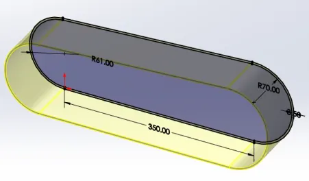
Transmission belt extrude feature used.
Fillet:- The Solidworks models have sharp edges as we model and want a final finish, a designer would want to make the surface ends as smooth as possible by making the egdes curved to join material in other planes. This can be done by using the fillet option. The radius of the fillet can be mentioned to obtion the required edges as per design.
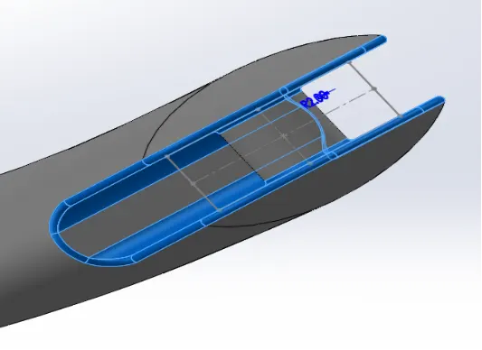
Kickstand fillet feature used.
Revolve boss feature:- This feature works around an axis, by selecting axis of a sketch it adds a round material by revolving around that axis. If there is no axis we can select an edge of a sketch and it gives us appropriate geometry.
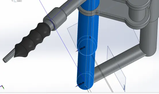
Front fork revolve boss feature
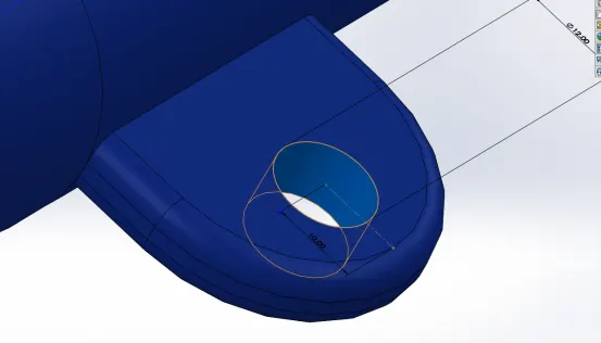
Extrude cut:- This feature cuts the geometry which we don’t need from the part or it can be used to give the desired shape to the sketch or solid part. When we draw sketch on the solid part and then we use extrude cut command it removes that part/surface.
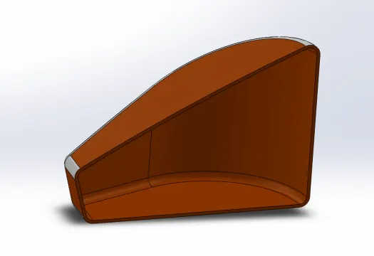
Shell:- The shell tool hollows out a part, leaves open the faces you select, and creates thin-walled features on the remaining faces. If any face on the model is not selected, we can shell a solid part, creating a closed, hollow model. We can also shell a model using multiple thicknesses. The Shell feature hollows out the inside of the solid, leaving a shell of a specified wall thickness. It lets you specify a surface or surfaces that you want to remove from the shell. ... When defining a shell, you can also select surfaces where you want to assign a different thickness.
Linear pattern:- Linear pattern is used to create single sketch to use multiple times. The spacing, angles and path can be given in this feature to draw or create pattern. This feature spaced uniformly along one or two linear paths.
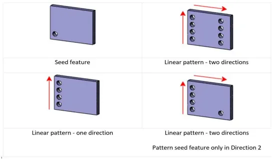
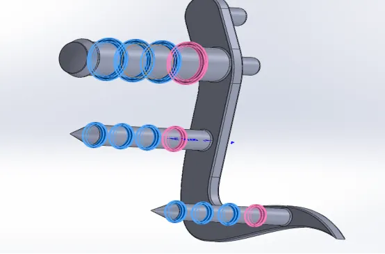
Chopper Pedal using Linear Pattern
Mirror:- This feature creates a copy of the solid part with respect to a reference. When this feature is applied it need plane or axis to mirror. Select the body which is to be mirror, select an axis or plane then apply feature and the mirrored part will get. Multibody parts: Apply feature to one or more multibody parts by selecting geometry pattern and using feature scope to choose which bodies should include the feature.
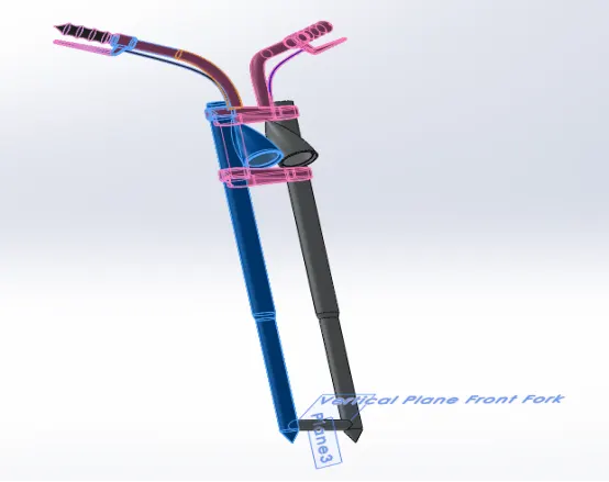
Mirror feature used to mirror front fork handle
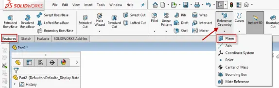
Reference geometry:- It defines the shape or form of a surface or a solid. This includes features such as planes, axes, co-ordinate system and points. This can be used according to need in a sketch.
Use of reference geometry example:
- Axis: If we want to pattern something and axis is not available by using reference geometry axis it gets easier to make pattern.
- Plane: If we need to sketch and there is need of plane by using reference geometry plane we can draw it and complete the sketch.
Projected curve:- The curve can be project by a sketch into a model to create a 3D curve. We can create multiple closed or open contour projected curves from a single sketch. Generally the curve can be intersection of two extruding surfaces. The curve which is created can be use as a path for the sketch of the part. Note: It does not create curve of an intersecting nature.
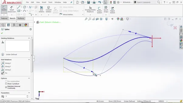
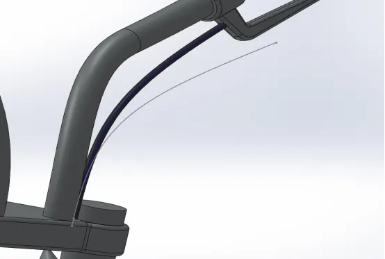
Curve feature used for handle bar cables.
Knit:- Use of knit surface tool to combine two or more faces and surfaces into one. It create a solid body when the knit surfaces form a closed volume or leave as a surface body.
Mate:- Mate creates geometric relationship between assembly and component. When we add mates, it defines the allowable direction of linear or rotational motion of component within its degree of freedom, visualizing the assembly’s behavior.
This feature includes:-
- Coincident mate: Coincident mate make two planar faces to become coplanar. This mate can move along one another but cannot be separated.
- Concentric mate: This makes two circular faces to become concentric and can move along the common axis.
- Tangent: This feature can be use between a face and plane to make tangent mate.
- Angular mate: This make angular relation between flat surface and the surface having some angle.
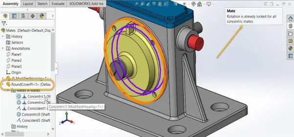
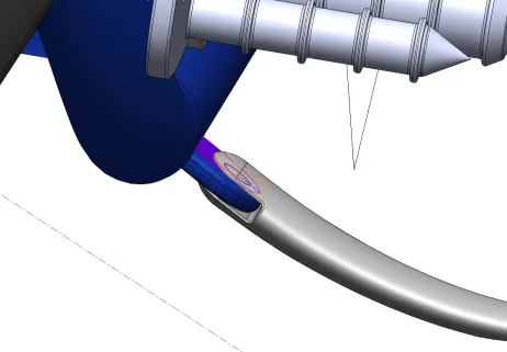
Coincident Mate of kickstand to Chassis. The angle of rotation is restricted.
Loft: The loft feature creates a shape by making transitions between multiple profiles and guide curves.
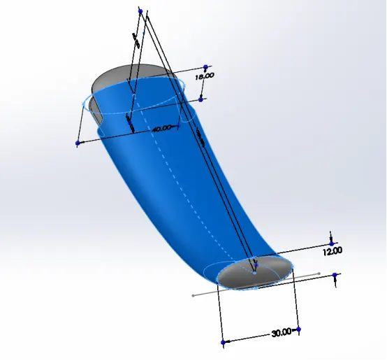
Dome: The dome feature calculates the distance using the radius of the arc as a basis for the dome. It creates a dome that is tangent to the adjacent cylindrical or conical face.
The main Solid Works features have been discussed.
We can proceed to the discussion of parts of the Chopper as was listed in the flowchart.
TRANSMISSION BELT
The belt transmits power produced by the engine to the wheel connected to the ground. The belt is made of rubber material to improve the friction coefficient such that there is minimum losses in power transmission to rear wheel.
The sketch of transmission belt as per the dimensions are fully defined on the front plane.
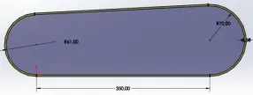
This sketch is then extruded to a width of 88 mm.
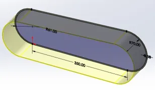
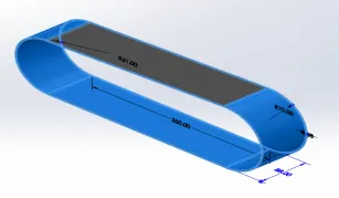
Fillets are added to edges of the transmission belt of radius 1mm.
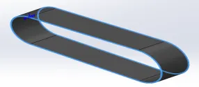
The transmission belt is thus obtained.
KICKSTAND
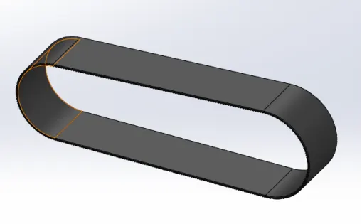
Firstly, the diameter of the kickstand is sketched on a plane, an ellipse as shown and extruded using the “Loft” option with respect to a reference line or a spline reference geometry.
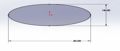
A profile is made on a different plane as the kickstand is curved and also the diameter changes with respect to the plane shown above and the reference spline. This is made using the Lofted Boss/Base option.
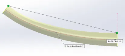
A sketch is then created on a plane as shown
On both sides a dome is created at the ends of the Kickstand.
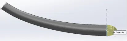
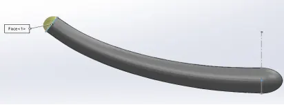
A rectangle is sketched to use the Cut extrude option to eliminate the material, thereby making space for the bottom bracket to help mount the kickstand onto the Chopper.
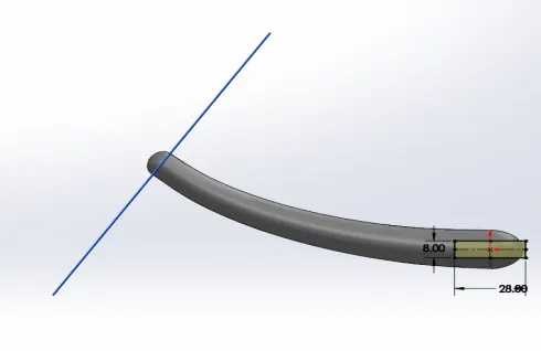
This is done by selecting the surfaces on top, bottom and side in the feature manager design tree of the material which has to be removed.
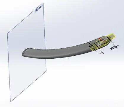
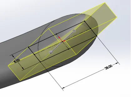
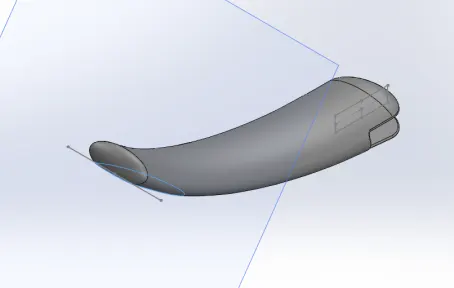
On the plane at the other side, a sketch of a line is drawn which is used as reference to remove material at the bottom of the kickstand using the Split option.
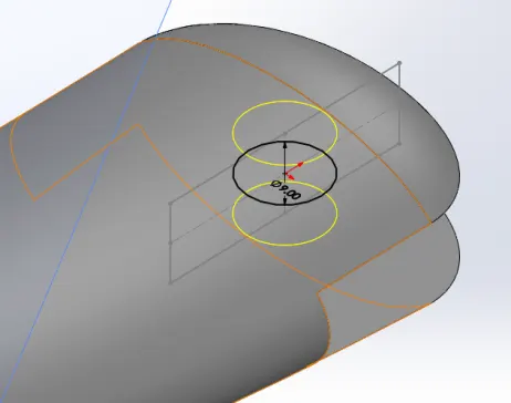
For the bottom bracket, a sketch of radius 9mm is drawn at the cross section of the kickstand on the bigger end, which is extruded on both sides using Boss Extrude option.
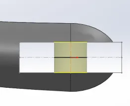
The material around the bottom bracket are then filleted with a 2mm radius.
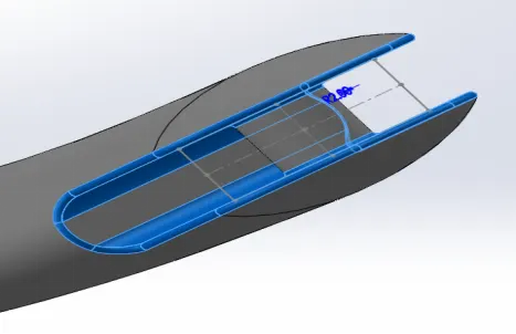
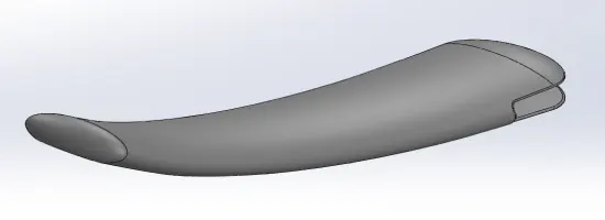
We thus obtain an image as shown, a design of the kickstand.
Front Fork
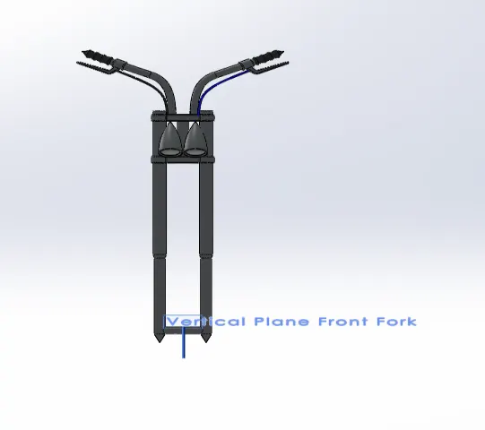
Firstly the suspension is modelled using the revolve feature and a guide plate is extruded on the top.
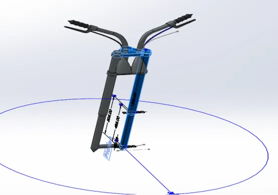
The Linear Pattern feature is used thereby creating the handle bars and the bottom joining plate of the two suspension rods for rigidity.
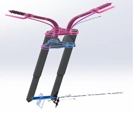
Lastly the dome feature is used to create the headlights and revolve feature for the handle bars.
There are finally mirrored and combined to get the complete part.
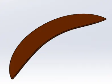
FRONT FENDER
The sketch for the thickness of the front fender is made with respect to an axis.
This sketch is extruded using the revolve feature with respect to the same axis.
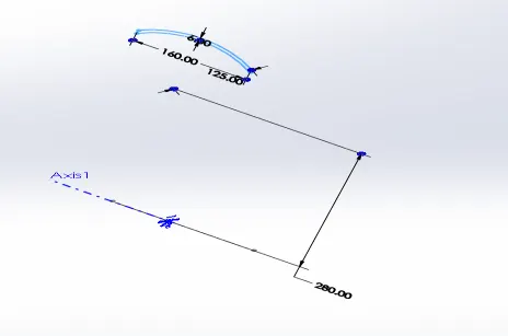
Sketches are drawn on perpendicular planes to get the required ends using the split feature.
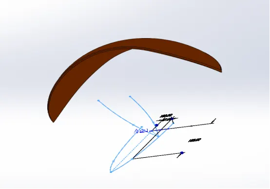
The fillets are added accordingly.
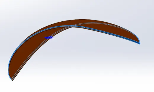
The front fender is obtained
REAR FENDER :
The same process is used to get the rear fender, only the dimensions vary.
The material used is metal and the colour - Sienna is used.
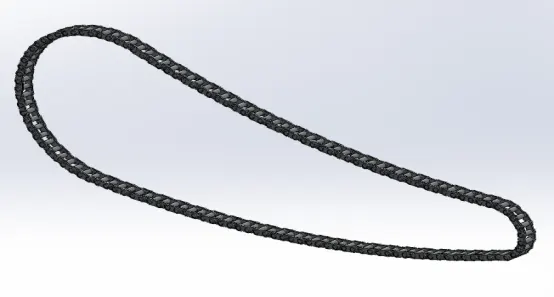
CHAIN
The blocks and pins are sketched and extruded. They are assembled such a way that they form links and have a certain degree of freedom between them such that the arrangement form a loop of chain links.
Each block is mirrored with respect to the mid plane to get the same block on either sides.
Chrome metal finish can be used for the chain material.
OIL TANK
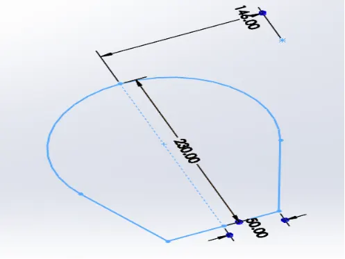
The sketch as shown is drawn as per the dimensions of oil tank in the top plane.
The sketch is extruded.
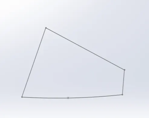
Another sketch is drawn in the Mid-plane and extruded.
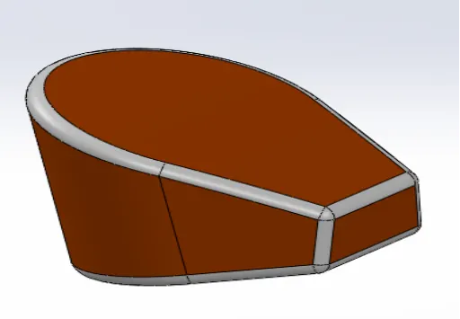
Fillet and shell feature is added to make the outer edges smooth and inner material removed to make a hollow part.
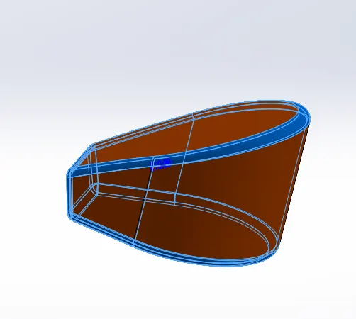
The result is a model of the oil tank with dimensions as per the sketches.
PEDAL
Sketch is drawn in the plane as per the dimensions to form a pedal structure after the sketch is extruded.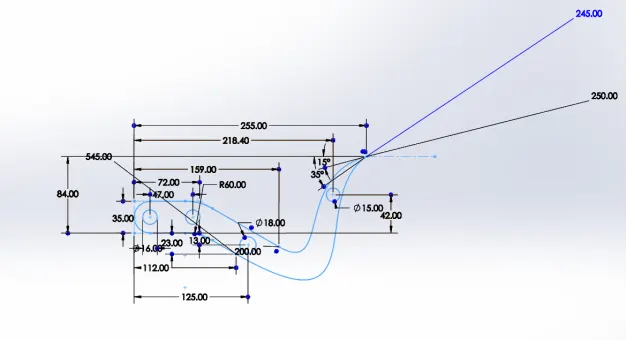
The bigger diameter rod is made by adding material using the revolve feature and a dome feature on the top.
The other two rods are extrudded from the sketch outer surface and chamfer feature is used for the cones on top ends.
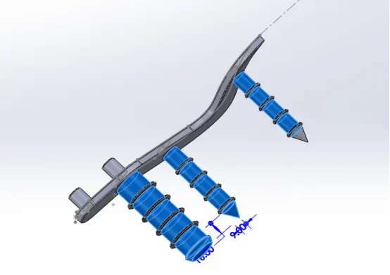
The linear pattern feature is used after the boss extrude feature for the circular fixtures on the rods.
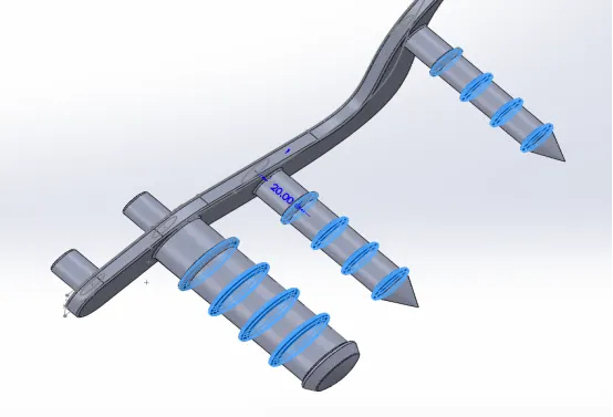
Fillets are added and final part is obtained.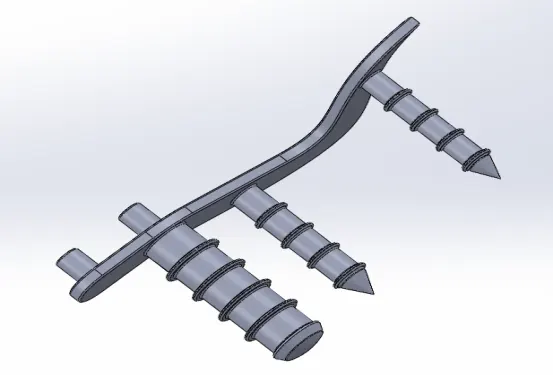
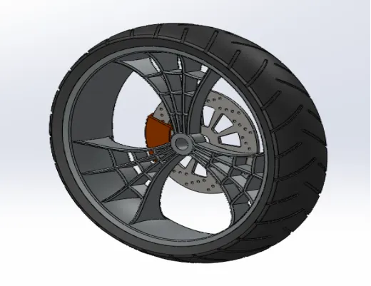
FRONT WHEEL
The sketches for the hub and tyre geometry is made
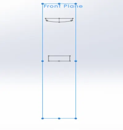
The material for the hub is added using the revolve feature based on the axis (the line bottom of the rectangle). The tyre is created using the revolve feature based on the hub.
The rims are made by sketches on top plane and filling material.
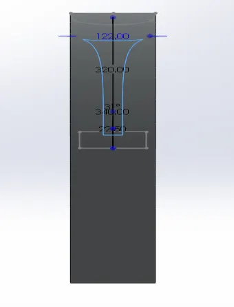
Cut extrude feature is used to remove material as shown on the top plane
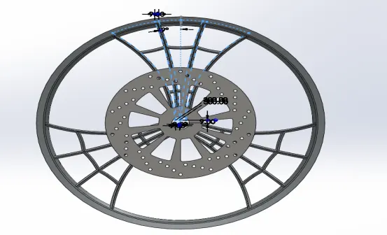
Boss extrude feature is used to join the design for rigidity and circular pattern feature to fill the space with three of such designs.
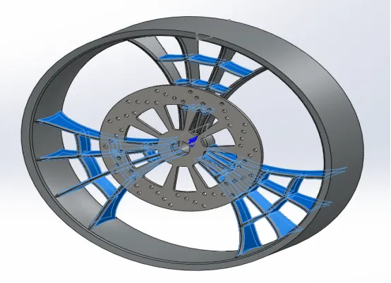
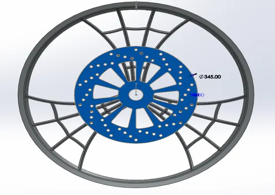
A sketch is drawn on right plane to extrude the brake discs and holes as per linear pattern feature is designed for heat dissipation
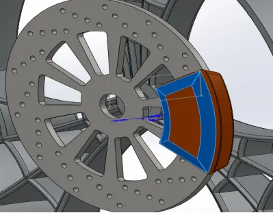
The brake callipers are extruded, fillets added and edges chamfered.
The revolve feature is used for tyre material and the friction is improved for grip by using cut extrude of the design as sketched in the Front-plane
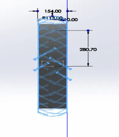
The final part of front wheel is obtained
REAR WHEEL
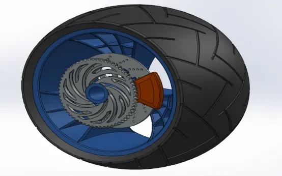
The same procedure and features are used to make the rear wheel. Only the dimensions vary and a sprocket is added using the same method as the brake discs were created with the required cross section and design. A circular patter is made for the grooves of the sprocket.
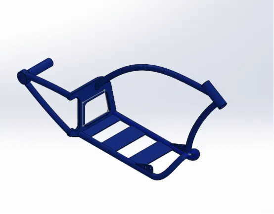
Chassis:- The chassis is the main frame of the chopper. It holds all the components such as front fork, pedals, kickstand, oil tank, engine, gas tank and rear wheel. It supports all the components and supports to the bike. The modelling of chassis starts with using chopper image for reference. It uses features such as extruded boss, splines, and revolving parts, making mirror and sweep. At the end whole part is filleted and it gives a nice appearance to the chassis asthe sharp edges are smooth. The appearance given to the chassis is Glossy Blue.
Features used to create the Chassis:
- Blueprint sketch
- Splines
- Curves
- Mirror
- Boss extrude
- Extrude cut
- Chamfer
- Dome
- Split
- Revolve
- Combine
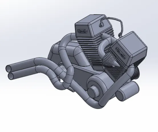
Engine:- The main part of the bike is engine. It is also called as heart of the bike. It provides necessary power to drive the bike. A picture is taken for the reference for modelling. The engine consists of parts like crank shaft, transmission pulleys and motor. The upper part of crank shaft the cooling fins were located. The air filters were drawn using spline and the exhaust system is also made with splines and projected curves and sweep feature. The edges of the engine were filleted and the appearance given is chrome metal.
Features used to create the Engine:
- Sketch
- Blueprint sketch
- Lines
- Circles
- Boss extrude
- Fillet
- Revolve
- Dome
- Circular pattern
- Chamfer
- Linear pattern
- Mirror
- Cut extrude
- Combine
- Mirror
- Curve
- Composite curve
- Split
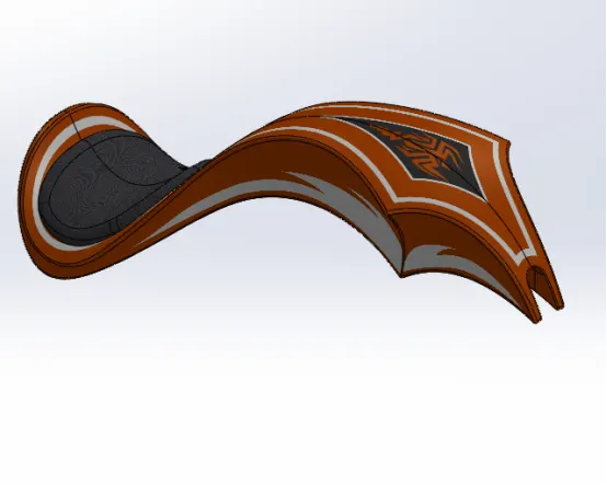
Gas Tank:- This part is mainly made with splines and sweep feature. The half part of the gas tank first created and then it is then mirrored about the plane. The two separated parts were made single part by using knit feature. The gas tank covers the oil tank and engine, and also it acts shield to prevent the heat from the engine. The seat was modelled on the top of the gas tank. The fillets were added to the edges of the gas tank. At the last shell feature were added to make it hollow from inside.
Features used to create the Gas tank:
- Blueprint sketch
- Spline
- Surface sweep
- Surface trim
- Surface boundary
- Surface loft
- Curve
- Mirror
- Surface knit
- Surface extrudes
- Fillet
- Extrude cut
- Shell
Assembly of the Chopper:- All the parts were modelled and were imported to assemble them. In assembly mate feature is most commonly used to locate and relate the parts with one another. Chassis is main component which is inserted first and then fixed. The other components were inserted one by one and by using planes for reference and giving the mate feature once the part gets fixed it floats with the main frame. Some parts were modified during assembly to make it perfect according to requirement.
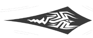
Decals:- A decal is something called a “transfer”, and it consists of a picture, image, pattern, or design that’s printed on metal body. We have added decals on Gas tank, Rear fender and Oil tank of chopper. It gives nice appearance to the chopper.

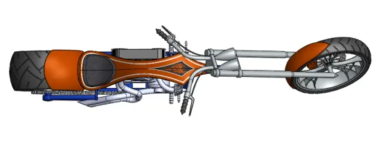
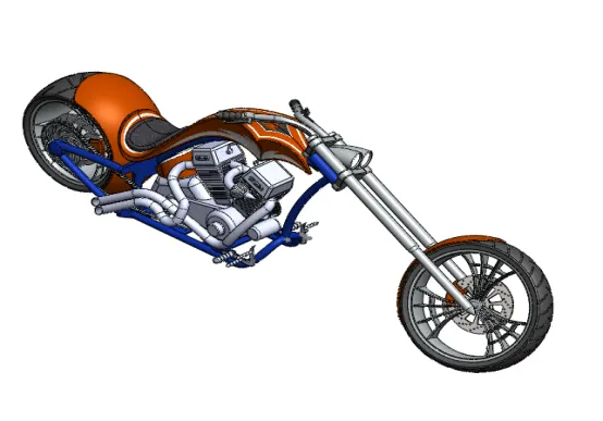
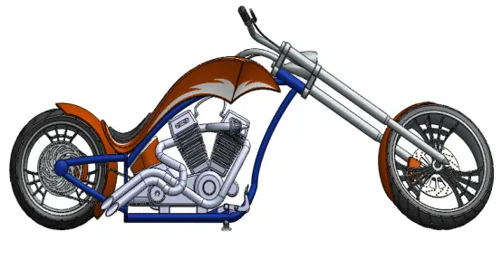
Rendering:- PhotoView 360 is a SOLIDWORKS add-in that produces photo-realistic renderings of SOLIDWORKS models. The rendered image incorporates the appearances, lighting, scene, and decals included with the model.
We can schedule the render as the render time depends on number of passes for rendering and based on the computer specifications.
We can make detailed adjustments in the final render window.
Below are a few rendered images of the Chopper.