Photo Realistic Rendering
MODELING OF AMERICAN 3D CHOPPER ON SOLID WORK
Report Submitted by
GOWTHAM S
Objective:
To create and assembly of American chopper bike using of solid work
overview
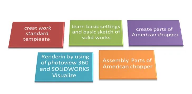
CREATE WORKING TEMPLATE :
1. First change dimension of drawing change MMGS (millimetre gram second)
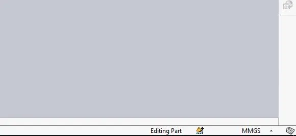
2.To set other basic setting depends upon my system configuration
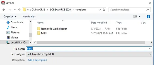
3.Save desire location in template part format
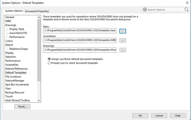
4.To change default template to new saved template
PARTS OF AMERICAN CHOPPER
Transmission Belt
Kickstand
Front Fender
Rear Fender
Chain
Oil Tank
Pedal
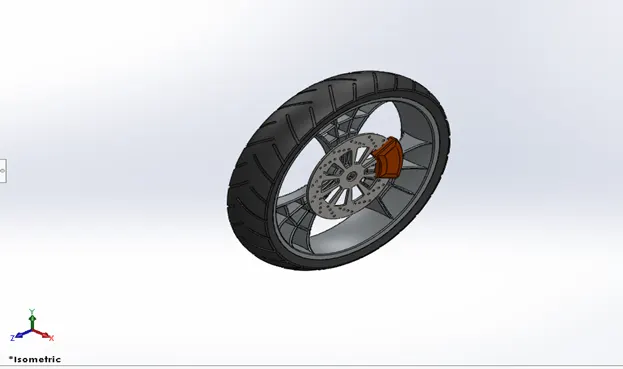
Front Wheel with Rim, Sprocket, Calipers
Rear Wheel with Rim, Sprocket, Calipers
Front Fork with Handle Grips
Chassis
Engine and Exhaust System
Gas Tank
Transmission Belt
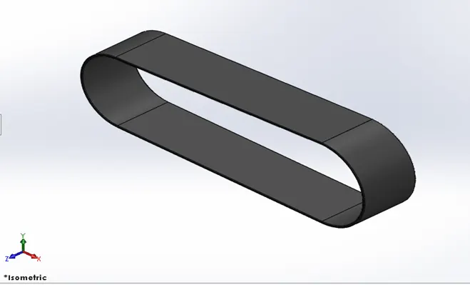
Feature used:
Boss-Extrude
Fillet
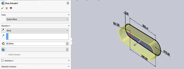
Boss-Extrude:
This is a handy feature for creating 3D solid Models in solid works. It is used to 2D sketch to 3d solid feature
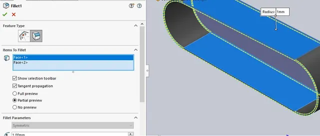
FACE FILLET:
In solid works whenever corners and edge of part need to be rounded fillets are chosen . face fillet can also be selected when face instead of edge picked
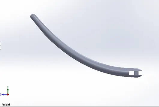
Kickstand
FEATURE USED:
Loft
Dome
Boss-Extrude
Split
Fillet
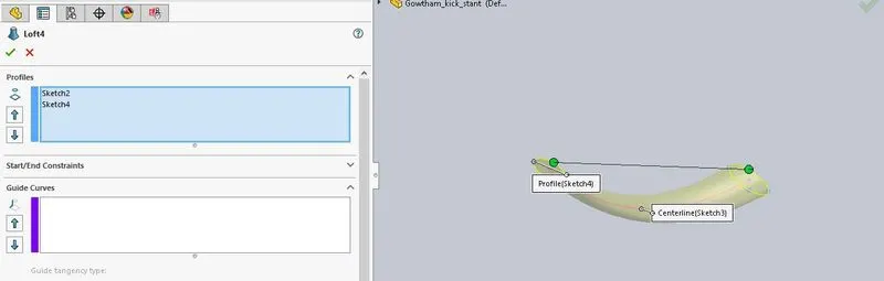
LOFT:
The loft feature in solidworks is generate complex geometry in a single feature. It does this by interpolating b/w various cross section of model
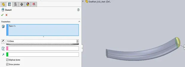
DOME:
Solidworks provide a tools that can be applied for just this scenario called dome
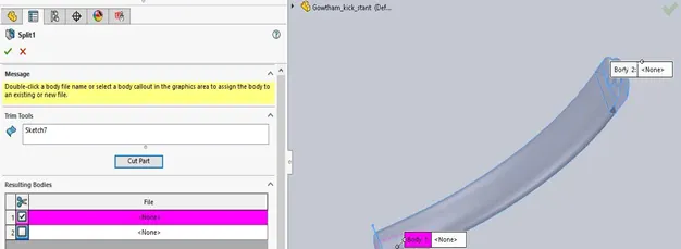
SPLIT:
Use split featureto creat multiple parts from an exciting parts.
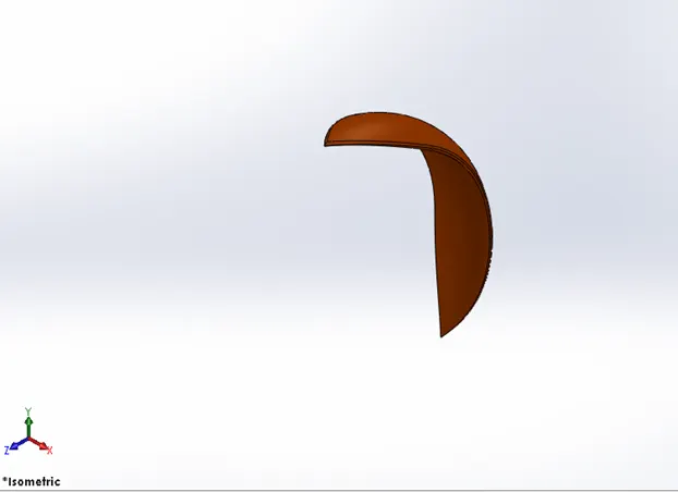
FRONT FENDER
FEATURES USED
Revolve
Split
Fillet
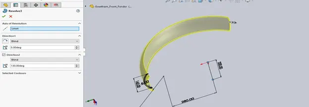
REVOLVE
Add material by revolving one or more profile arount a centreline
CHAIN
FEATURE USED:
Boss-Extrude
Fillet
Circular pattern
Mirror
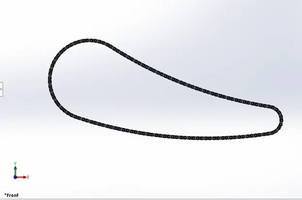
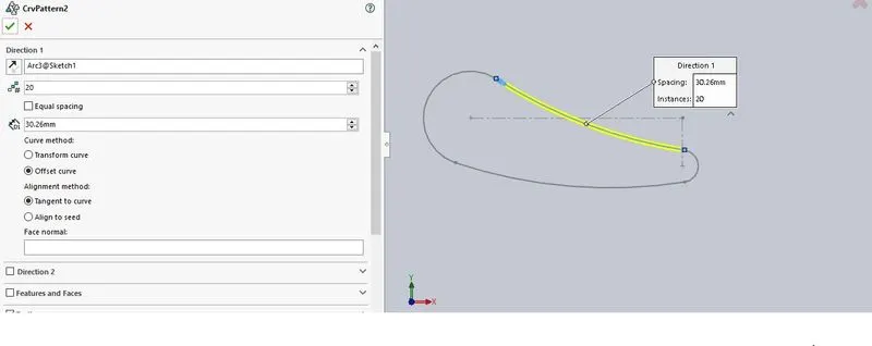
CIRCULAR PATTERN:
This command allows you to create copies of objects arranged in a pattern both easier and faster
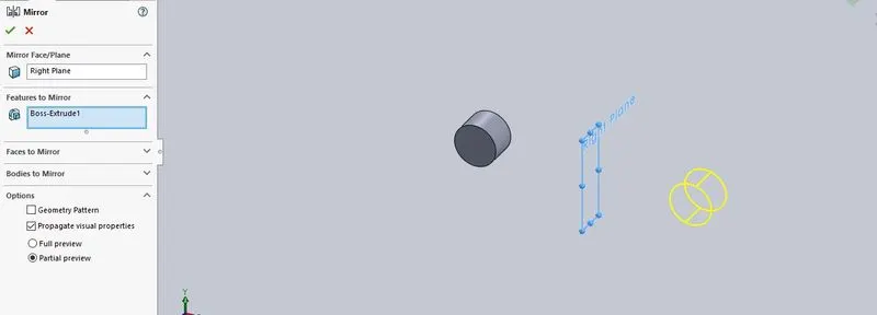
MIRROR:
Mirroring is another way that solid works can create a copy of an existing object. Additionally you must choose a plane to mirror parts
PEDAL
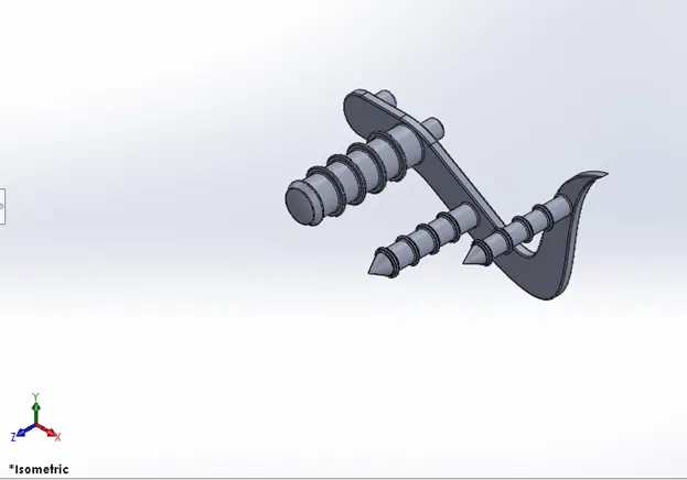
FEATURES USED:
Boss-Extrude
Fillet
Dome
Revolve
Linear pattern
Chamber
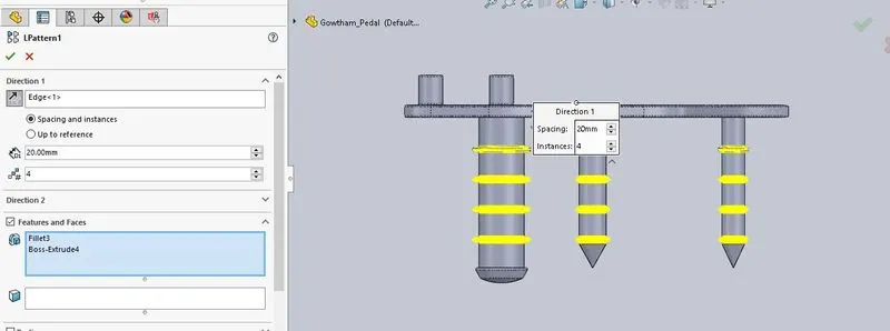
LINEAR PATTERN:
The linear pattern command is used to drive features faces or bodies in a linear direction
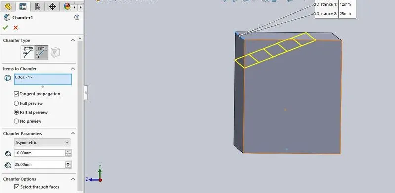
CHAMPER:
The chamber tool create a beveled feature on selected edge, faces or a vertex
OIL TANK
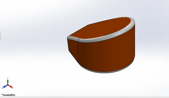
FEATURE USED:
Boss-Extrude
Fillet
Combine
Shell
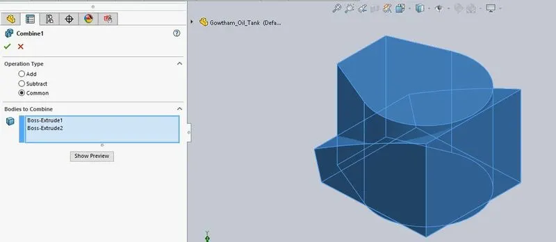
COMBINE:
Combine tool used to multiple bodies converted to single bodies and also it have three option add, subtract and common
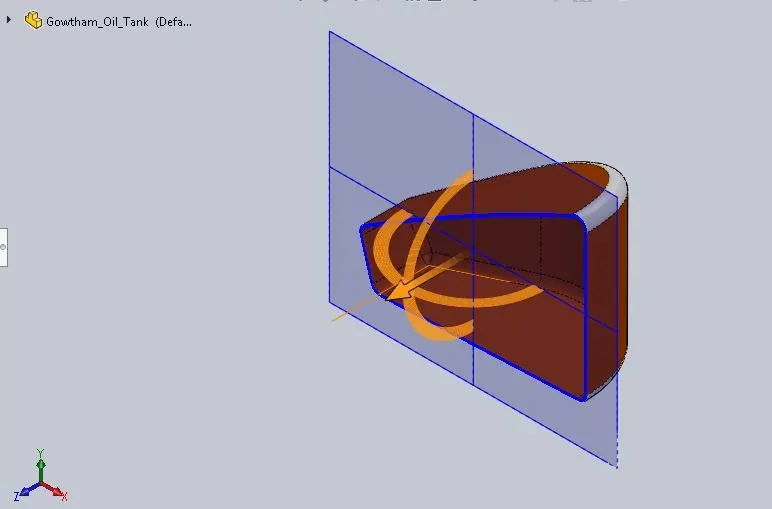
SHELL:
The shell tool is mainly for shelling process in which the material removed from the inner body by keeping small thickness and result a hallow model
FRONT WHEEL
FEATURES USED:
Boss-Extrude
Fillet
Revolve
Circular pattern
Chamber
Cut Extrude
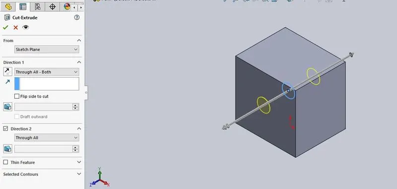
CUT EXTRUDE:
This is handy feature to aid material removal of 3D model using 2D sketch
ENGINE
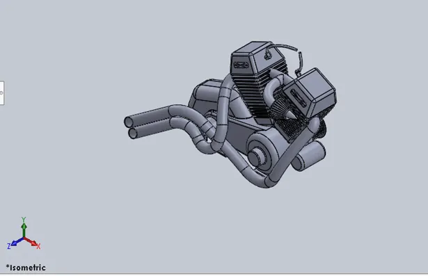
FEATURES USED:
Boss-Extrude
Fillet
Revolve
Circular pattern
Chamber
Cut Extrude
Sweep
Curve
Dome
Mirror
Split
GAS TANK
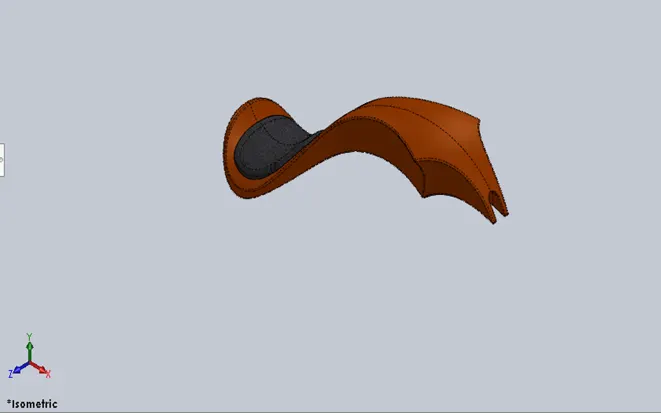
FEATURES USED:
Surface Extrude
Fillet
Surface knit
Surface loft
Boundary surface
Surface Sweep
Curve
Surface trim
Mirror
Shell
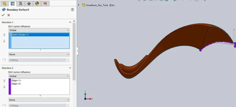
BOUNDARY SURFACE:
The boundary surface feature lets create surface that can be tangent or curvature continuous in both direction.
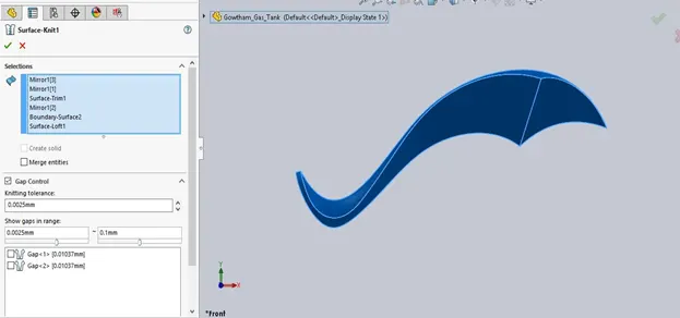
SURFACE KNIT:
Use knit surface tool to combain two or more faces and surface into one
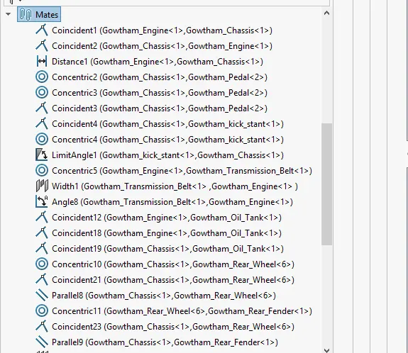
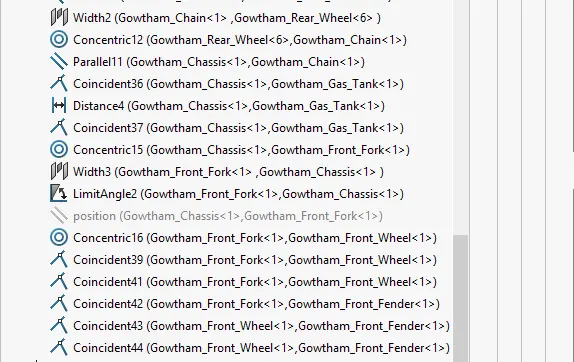
ASSEMBLY
Adding a components to an assembly creates a link b/w the assembly and the components
RELATION USED:
Coincident
Distance
Concentric
Width
Parallel
Angle
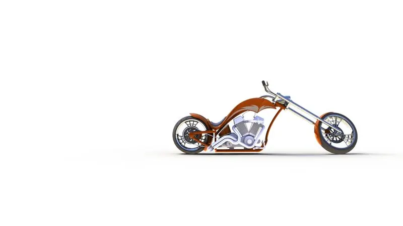
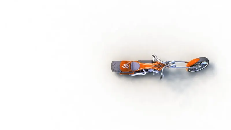
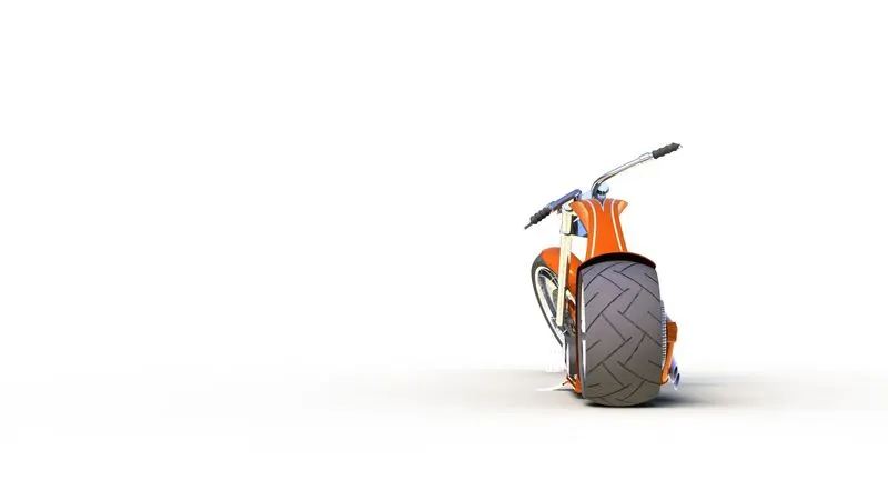
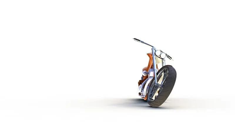
RENDERING
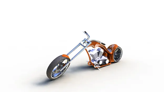
The rendered image by add in lights, camera, scene, decals and also include with model by used to PHOTO VIEW 360 and SOLIDWORKS VISUALIZE
RANDERING IMAGE:
CONCLUSION:
Finally created chopper parts , assembly chopper parts and rendering succesfully,
RENDERING IMAGE
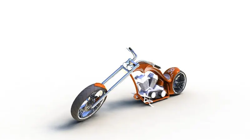
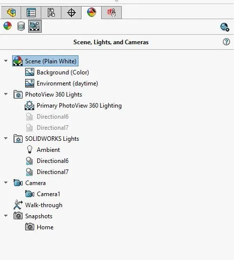
Note: my system have only 2GB ram , I unable open solid works visualize. so i rener only Photoview 360