Challenge

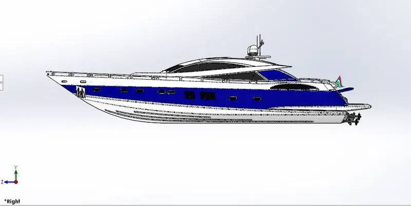
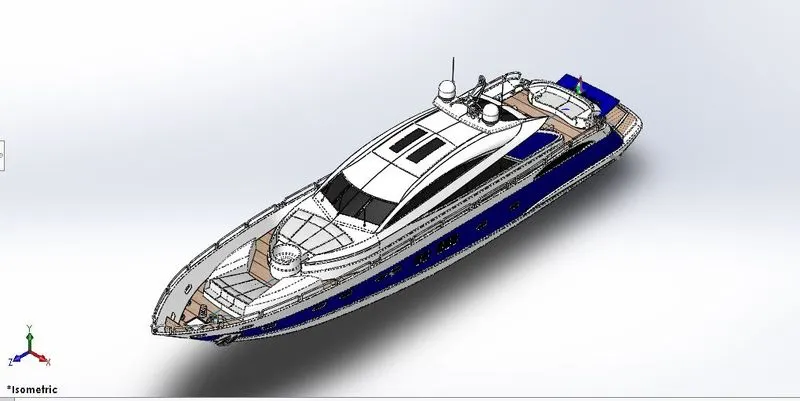
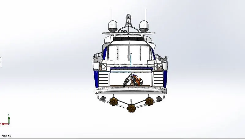
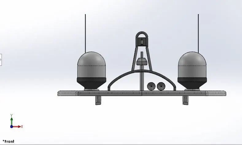
Radar Mast & Final Assembly of Yacht

                                                             PROJECT REPORT


                                             MODELING OF YACHT ON SOLID WORKS


Introduction :

                                         A yacht is a sailing or power vessel used for pleasure, cruising, or racing. There is no standard definition, so the term applies to such vessels that have a cabin with amenities that accommodate overnight use. To be termed a yacht, as opposed to a boat, such a pleasure vessel is likely to be at least 33 feet (10 m) in length and may have been judged to have good aesthetic qualities.

Aim :

                       To create in this project various part of Yacht in solid works  and  assembly of all parts.


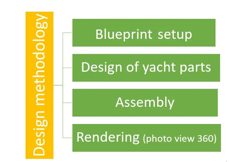
                                                            Design methodlogy
                                             

The  Different Parts Of Yacht :


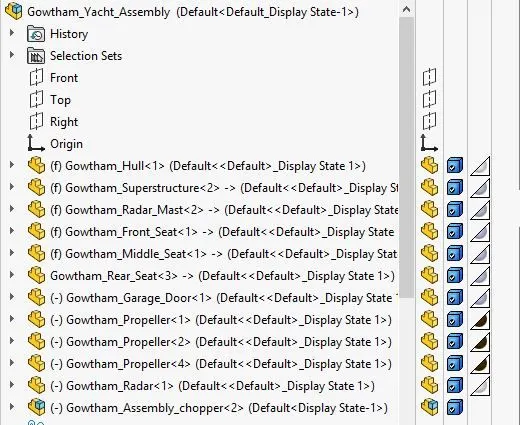
                                                                                            1.Propeller

                                                                                              2.Radar 

                                                                                              3.Hull

                                                                                              4.Door

                                                                                              5.Front Seat

                                                                                              6.Middle Seat

                                                                                              7.Rear Seat

                                                                                             8.SuperStructure

                                                                                             9.Radar Mast

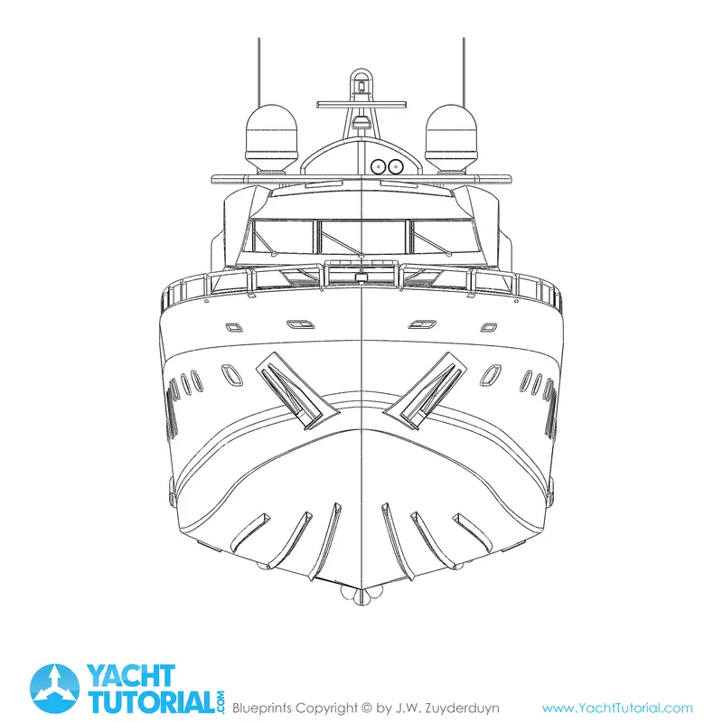
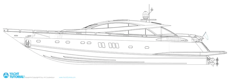
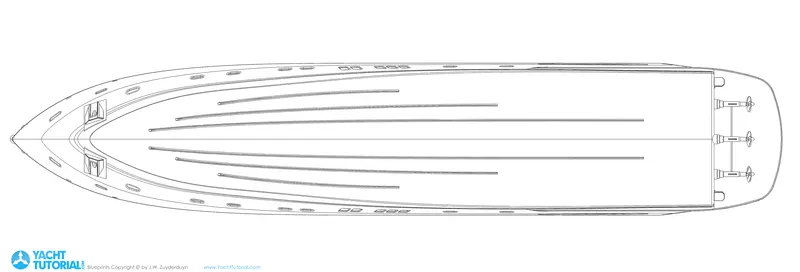
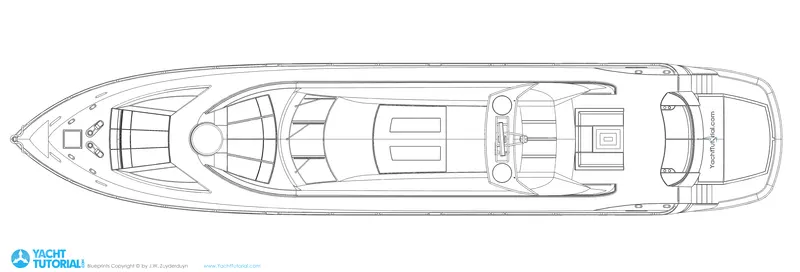
                                                                   Blueprint setup 

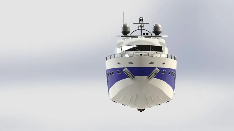
Front View:

                    1. Create sketch on Front plane         

                     2. Insert front view image   

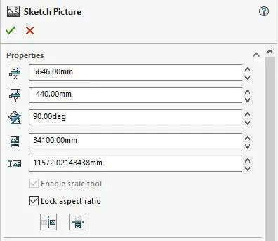
                     3. set properties of image
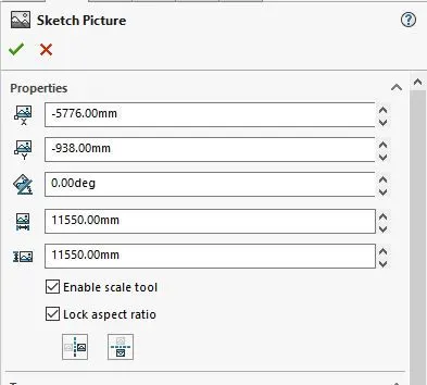


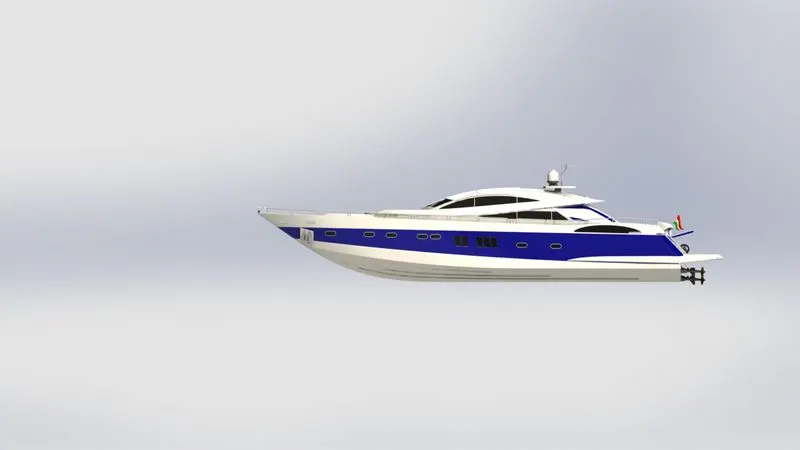
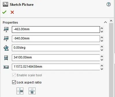
Side View :

                    1. Create sketch on Right plane         

                     2. Insert front view image of Yacht   

                     3. set properties of image


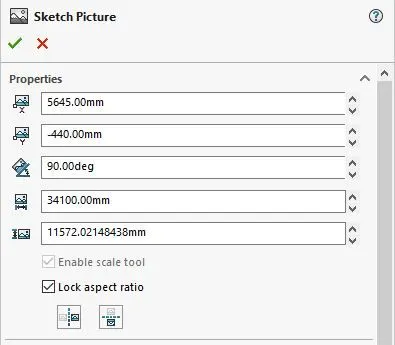
Bottom View :

                    1. Create sketch on Top plane         

                     2. Insert bottom view image  Of Yacht  

                     3. set properties of image
                      

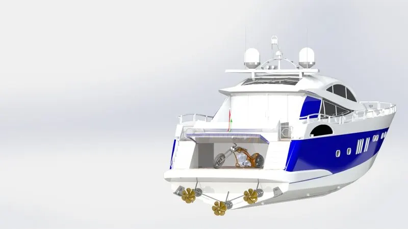
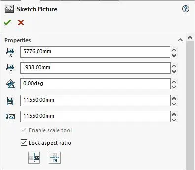
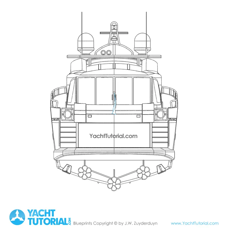
Back View :

                    1. Create new  plane   (offset distance 32920mm)

                     2. change name Plane 1 into back plane        

                     3. Insert back view image  Of Yacht  

                     4. set properties of image
                                                            

Top View :

                    1. Create new  plane   (offset distance 10000mm)

                     2. change name Plane 2 into top plane        

                     3. Insert back view image  Of Yacht  

                     4. set properties of image
                       

                                                             DESIGN OF YACHT PARTS


                                                                       PROPELLER

Features used: 

                       1.Revolve

                       2.Create plane

                       3.Solid loft

                       4.Fillet

                       5.Extruded cut

                       6.Circular pattern


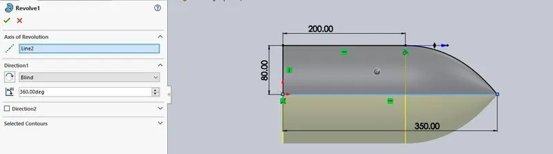
Revolve : 

              Draw 2d sketch on given dimension

              Select  revolve in features

              select on correct axis
                             

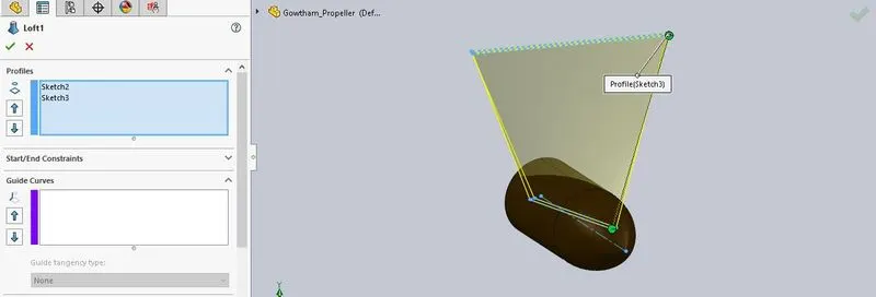
Solid loft :

                  Draw 2d sketch on given dimension

                  Select  Loft in features

                  Select two sketch in profile box
                                 

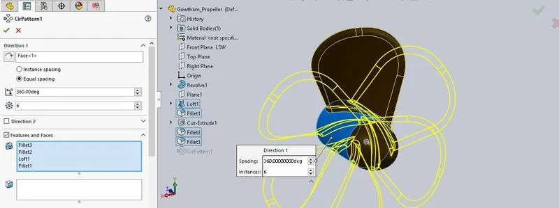
Circular pattern :

                            Select  Circular Pattern in features tabs

                            Select all faces of entity


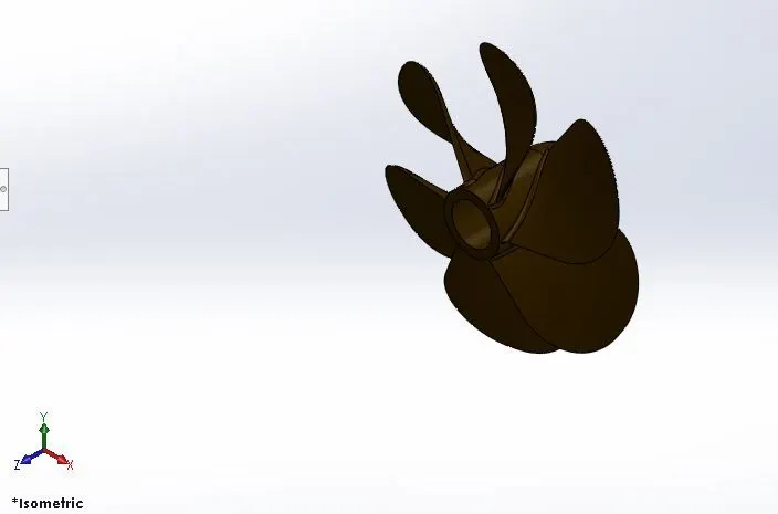
                                                  FINAL IMAGE OF PROPELLER


                                                                    RADAR


Features used: 

                                  1.Boss extrude

                                   2.Fillet

                                   3.Extrude cut

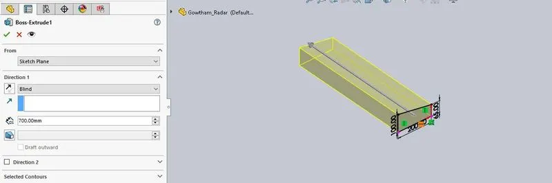
Boss extrude :

                  Select  Extrude in features tabs

                 Seleck sketch plane  and give distance 700mm 
                                          

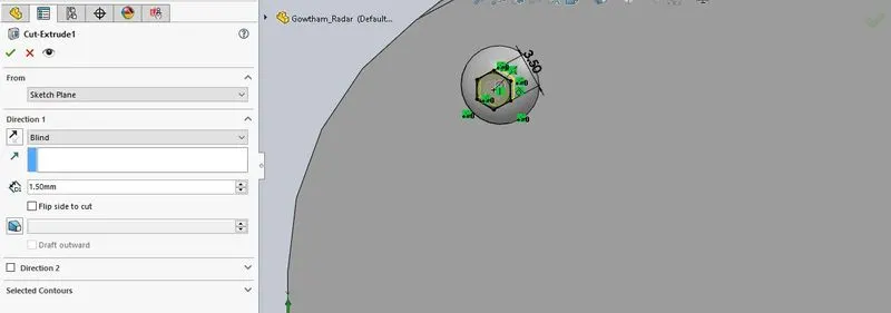
Extrude cut :

                     Select  Extrude cut in features tabs

                     Seleck sketch plane  and give distance 1.50 mm


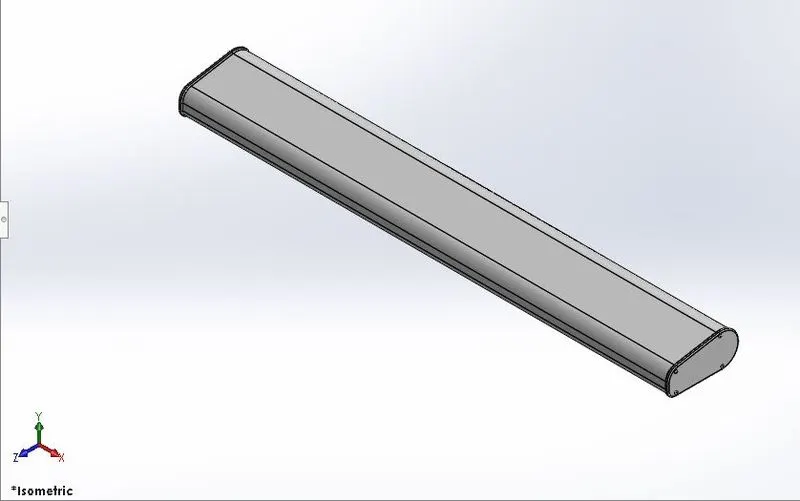
                                                  FINAL IMAGE OF RADAR


                                                                          HULL

Features used: 

                        1.Project Curve

                         2.Surface loft

                         3.Surface trim

                         4. Surface Extrude

                         5. Surface knit

                         6. Sweep

                         7. Boss Extrude

                         8. Cut Extrude

                         9. Linear Pattern

                        10. Fillet

                        11. Chamber

                        12. Create Deck surface

                        13. Mirror

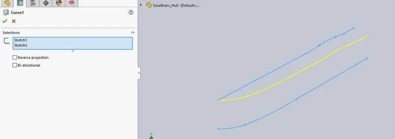
Project Curve :

                       Draw 2d sketch on given dimension

                       select project curve in Features tabs

                       select two sketch and give ok
                                                          

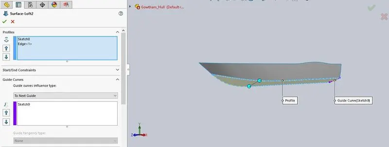
Surface loft :

                        Draw 2d sketch on given dimension

                        select surface loft in surface Tabs

                        select profile and guide curve 
                                                         

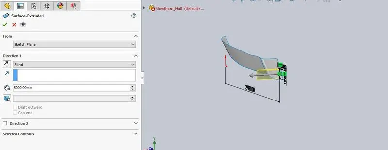
Surface Extrude :

                        Draw 2d sketch on given dimension

                        Select surface Extrude in surface Tabs

                        Select sketch plane  and give distance 5000 mm
                                                             

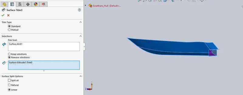
Surface trim:                           

                        Select surface Trim in surface Tabs

                        Select trim tool surface and removed surface or keep surface
                                                            

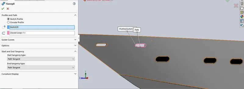
Boss Sweep :

                Draw profile sketch and path sketch on given dimension

               Select sweep in features Tabs

                Select profile sketch and path sketch 
                                                              

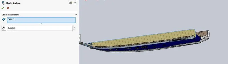
Create Deck surface

                                 This surface is used to create super structure

                                 Select Offset surface in Surface tabs

                                 select face and set offset distance 0 mm
                                                             

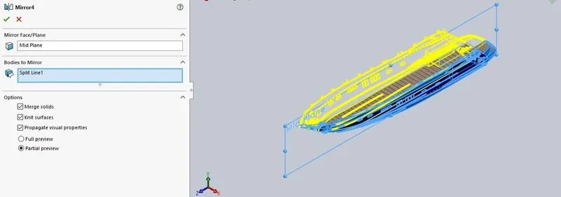
Mirror :

              select mirror in features tabs

              select all bodys of hull 

              select mirror plane and give ok
                                                             

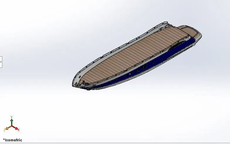
                                                  FINAL IMAGE OF HULL


                                                                            DOOR


Features used: 

                       1.Extrude cut

                       2.Shell

                       3.Mirror

                       4.Fillet


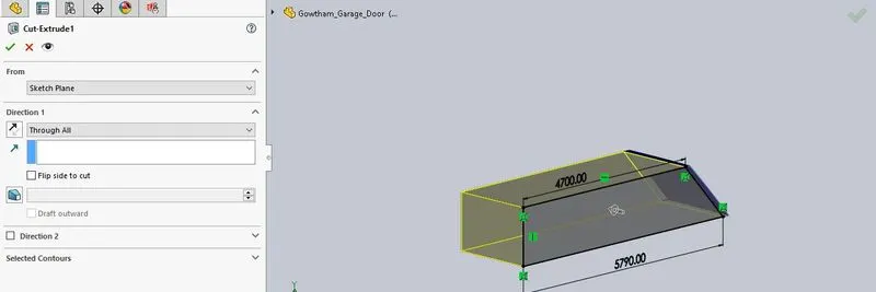
Extruded cut:

                        Select  Extrude cut in features tabs

                        Seleck sketch plane  and direction to through all


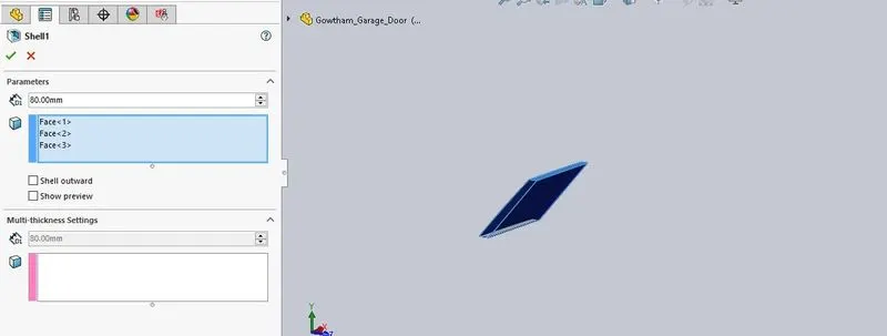
Shell:

            Select  shell in features tabs

            Seleck three faces and set shell thickness 80 mm
                                                       

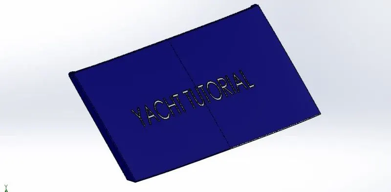
                                                  FINAL IMAGE OF DOOR


                                                                        FRONT SEAT

Features used: 

                       1.Extrude cut

                       2.Shell

                       3.surface loft

                       4.Dome

                       5.surface knit

                       6.Mirror

                       7 .Fillet

                       8.chamber

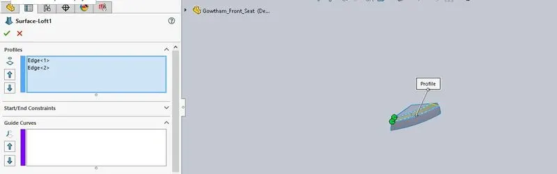
Surface loft :

                        Draw 2d sketch on given dimension

                        select surface loft in surface Tabs

                        select profile and guide curve 
                                                                     

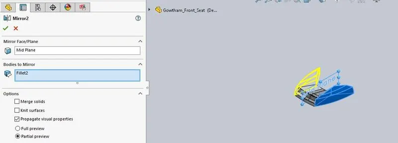
Mirror :

              select mirror in features tabs

              select required bodys to mirror

              select mirror plane and give ok
                                                                            

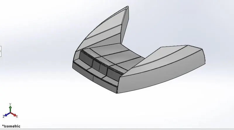
                                                  FINAL IMAGE OF FRONT SEAT
                                                                       

                                                                    MIDDLE SEAT

Features used: 

                       1.Extrude cut

                       2.Boss extrude

                       3.Fillet

                       4.Mirror

                       5.chamber

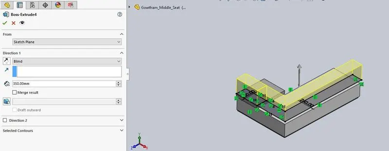
Boss extrude :

                       Select  Extrude in features tabs

                      Seleck sketch plane  and give distance 700mm 
                                                  

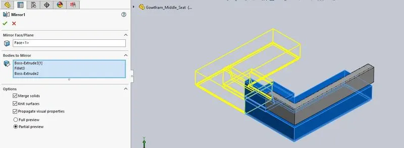
Mirror :

              select mirror in features tabs

              select required bodys to mirror

              select mirror plane and give ok
                                                 

Extrude cut :

                        Draw 2d sketch in given Dimension

                        Select  Extrude cut in features tabs

                        Seleck sketch plane  and direction to through all
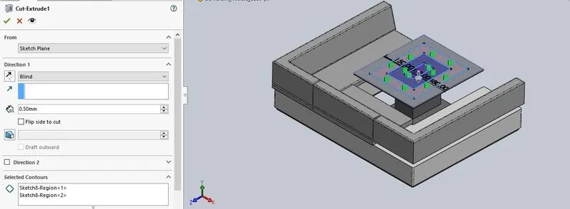


                                                  FINAL IMAGE MIDDLE SEAT
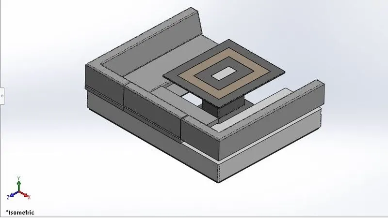
                                                                  

                                                                            REAR SEAT 

Features used: 

                       1.Extrude cut

                       2.Boss extrude

                       3.Surface sweep

                       4.Mirror

                       5.Surface trim

                       6.surface offset

                       7.Surface loft

                       8.Surface knit

                       9.Surface extend

                      10.Chamber

                      11.Fillet

Surface sweep :     

                        Draw profile sketch and path sketch on given dimension

                        select surface Sweep in surface Tabs

                        select profile and path sketch
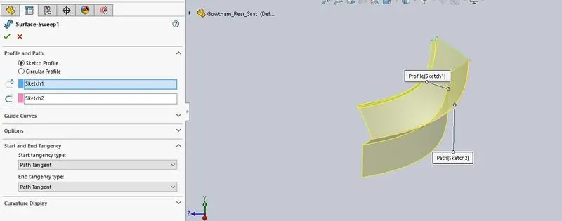
                                                                 

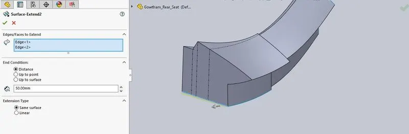
Surface extend :

                          select surface extend in surface Tabs

                          select required edge to extend and given distance 50 mm


Mirror :

              select mirror in features tabs

              select required bodys to mirror

              select mirror plane and give ok
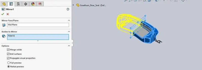
                                                                  

                                                  FINAL IMAGE OF REAR SEAT
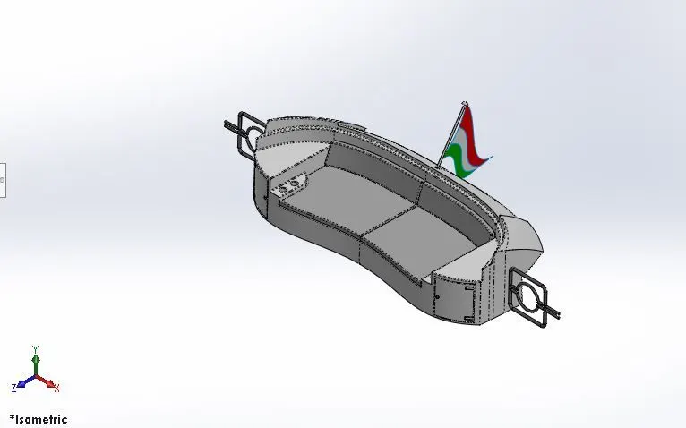
                                                                           

                                                                  SUPER STRUCTURE

Features used: 

                       1.Surface extrude

                       2.Ruled surface

                       3.Surface sweep

                       4.surface knit

                       5.Surface trim

                       6.surface Extend

                       7.surface offset

                       8.Extrude cut

                       9.Boss extrude

                     10.Mirror

                     11.Fillet

                     12.Chamber


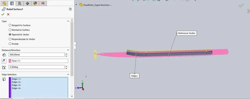
Ruled surface:

                       Select required edge to rulled surface

                       set tapperd angle 5 degree and distance 500 mm
                                                  

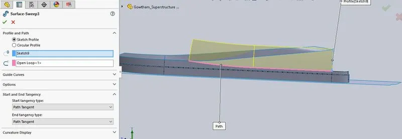
Surface sweep :     

                        Draw profile sketch and path sketch on given dimension

                        select surface Sweep in surface Tabs

                        select profile and path sketch
                                                       

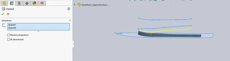
Project Curve :

                       Draw 2d sketch on given dimension

                       select project curve in Features tabs

                       select two sketch and give ok
                                                         

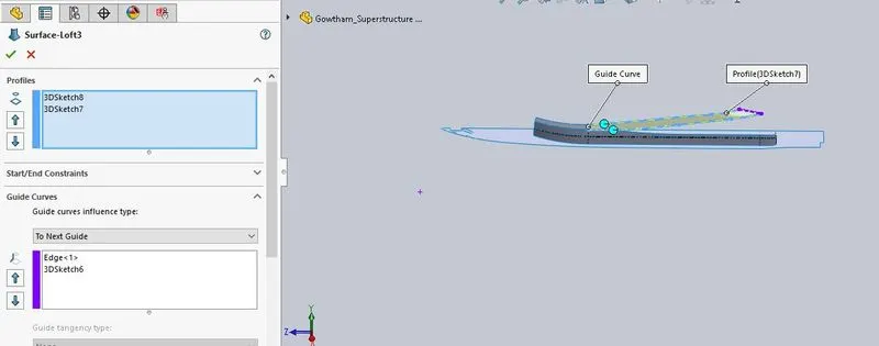
Surface loft :

                        Draw 2d sketch on given dimension

                        select surface loft in surface Tabs

                        select profile and guide curve 


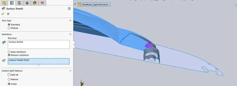
Surface trim:                           

                        Select surface Trim in surface Tabs

                        Select trim tool surface and removed surface or keep surface
                                                                

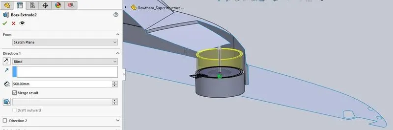
Boss extrude :

                       Select  Extrude in features tabs

                      Seleck sketch plane  and give distance 560mm 
                                                              

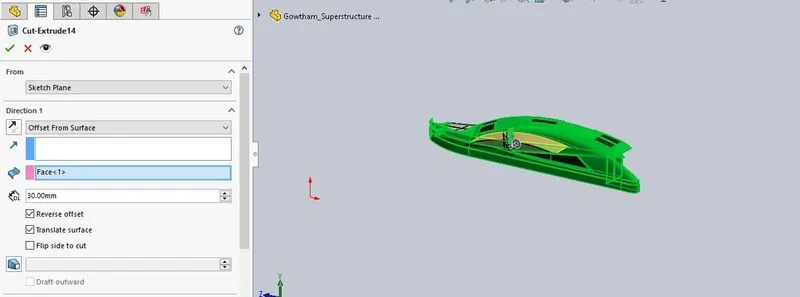
Extruded cut:

                        Select  Extrude cut in features tabs

                        Seleck offset surface  and select face

                        select reverse offset and give distance 30mm
                                                                  

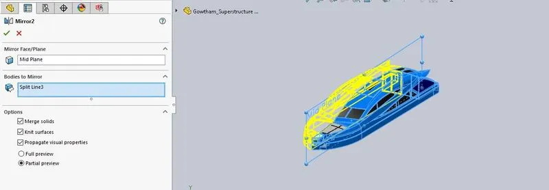
Mirror :

              select mirror in features tabs

              select required bodys to mirror

              select mirror plane and give ok
                                                                    

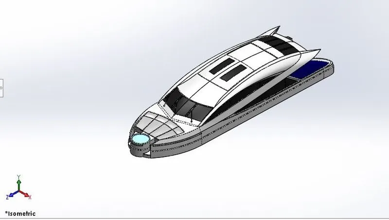
                                                  FINAL IMAGE OF SUPER STRUCTURE
                                                  

                                                              RADAR MAST

Features used: 

                       1.Boss extrude

                       2.Extrude cut

                       3. Boss sweep

                       4.Mirror

                       3.Fillet

                       5.chamber

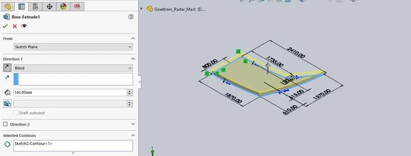
Boss extrude :

                       Select  Extrude in features tabs

                      Seleck sketch plane  and give distance 560mm
                                                            

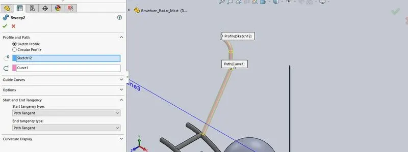
Boss Sweep :

                Draw profile sketch and path sketch on given dimension

               Select sweep in features Tabs

                Select profile sketch and path sketch 
                                                          

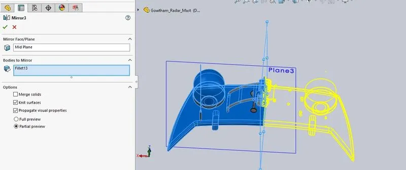
Mirror :

              select mirror in features tabs

              select required bodys to mirror

              select mirror plane and give ok


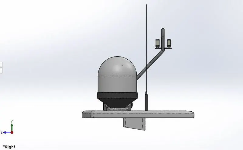
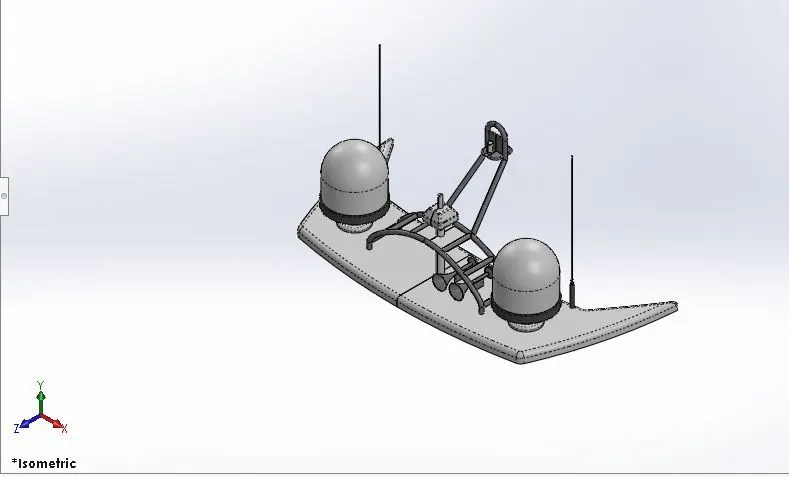
                                                  FINAL IMAGE OF RADAR MAST
                                                             

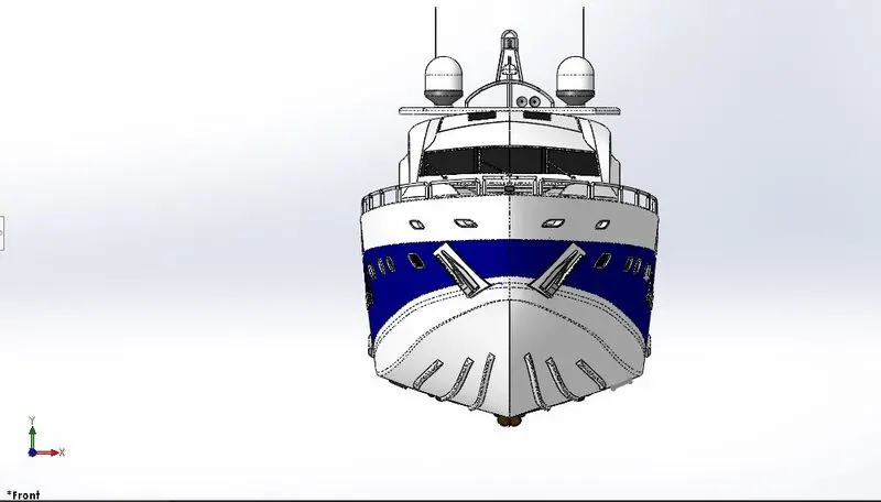
                                                                    ASSEMBLY

Relation used:

                         1. coincident

                         2. Distance

                         3. Concentric

                         4. Parallel
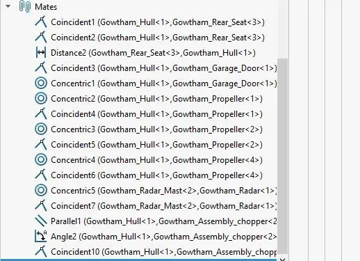
                                                                                       

coincident :

                       Select mid plane of hull amd mid plane of rear seat

                       click mates tab amd make coincident  
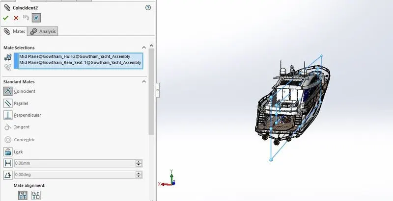
                                                

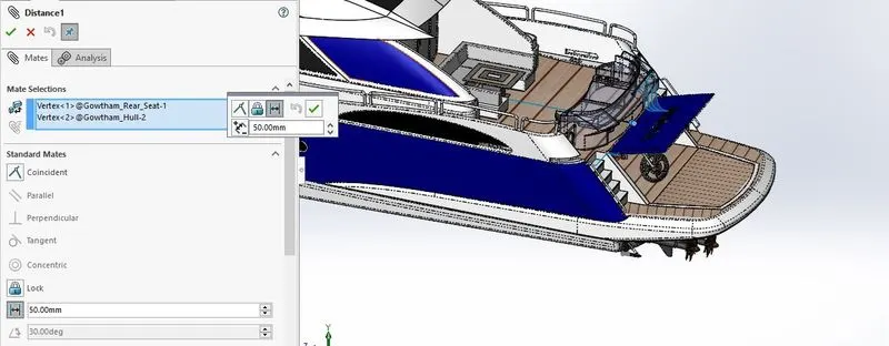
Distance :

                     Select vertex of rear seat and vertex of hull back end

                     click mates and give distance 50 mm
                                                   

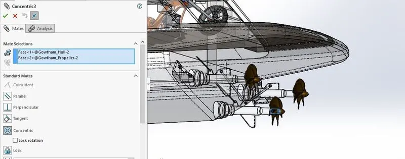
Concentric :

                      Select inner face of propeller and outer face propeller rod in hull

                       Make mates concenric relation and click ok


                                                        FINALL IMAGE OF ASSEMBLY
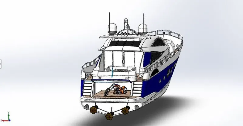
                                                                 

                                                                    RENDERING

Workflow

  1. With a model open, click Tools > Add-In and add in PhotoView 360.
  2. Start a preview in the graphics area or open the preview window to see how changes you make to the model affect the rendering.
  3. Edit appearances, the scenes, and decals.
  4. Edit lights.
    By default, lighting is off in PhotoView. With lights off, you can use the realistic lighting provided by scenes, which is usually sufficient for rendering. You typically need additional lighting in PhotoView to illuminate occluded spaces in the model.
  5. Edit photoview options .
  6. When you are ready, perform a final render either now ( PhotoView > Final Render ) or later ( PhotoView > Schedule Render ).

    If annotations or dimensions are visible in your model, a dialog box appears with options to include the dimensions and annotations or render without them.

    If you have not added a camera or turned on perspective view, which provide more realistic, higher quality renderings, a dialog box appears. You can turn on a camera or perspective view from the dialog box or continue without them.

  7. Make detailed adjustments in the final render window .

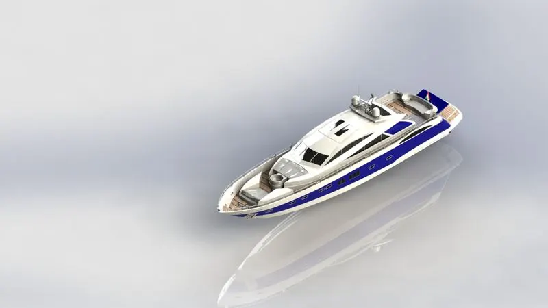
                                               sample render images


CONCLUSION : 

                           our yatcht final design and rendered sucessful . During this project i faced  lot of troubled in design of some parts but this troubled teached lot of new techniques in design. The result of this project i learned design ,assembled and rendered of yacht successfully.  

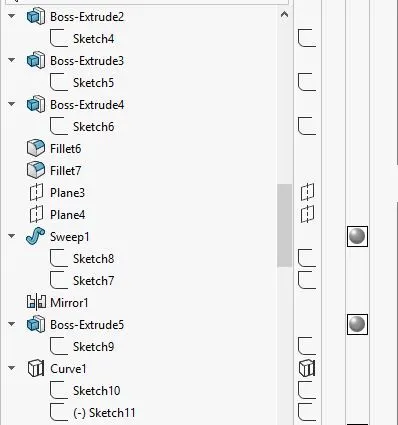
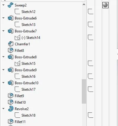
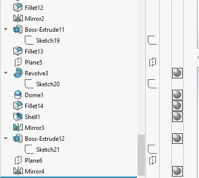
                                                              Radar mast
                                                                     

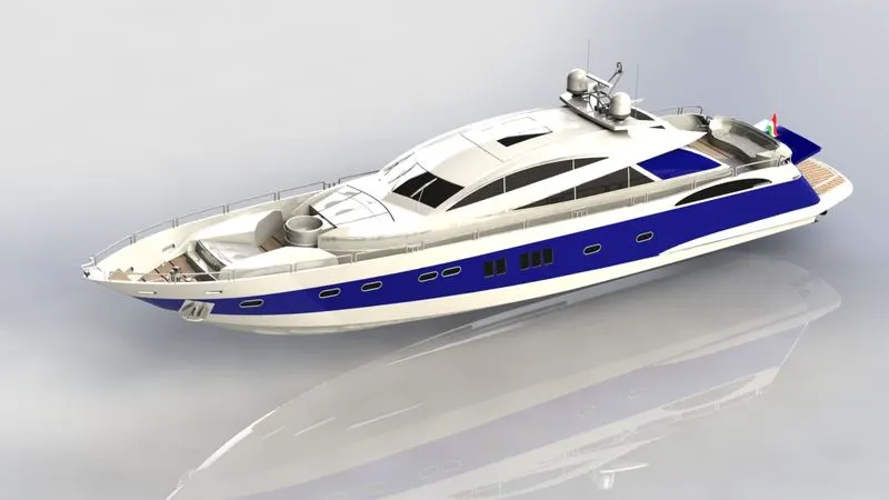
                                         Yacht assembly
drive link for Assembly of yacht :  https://drive.google.com/file/d/10w1TY4gwYb2UlCr8xSRKaNuYmTz6w2iP/view?usp=drivesdk


Your portfolio, next

Ship work like this
in your own course.

Talk to a career counsellor

Free 20-minute call. We'll map the right course to where you want to work.

By submitting you agree to our Terms and Privacy Policy.

Talk to a career counsellor

Free 20-minute call. We'll map the right course to where you want to work.

By submitting you agree to our Terms and Privacy Policy.