Advanced Sheet Metal Design Using NX Cad Challenge_6_Bracket
ADVANCE SHEET METAL DESIGN USING NX12.0- CREATE BRACKET
INTRODUCTION:
Brackets which are made of sheet metal is widely used in mounting device like antennas, automobile unit etc.
OBJECTIVE:
The objective of this project is to design a sheet metal bracket using nx12.0 sheet metal application workbench, And for drafting the sheet metal bracket.
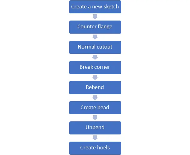
The following steps where undertaken while designing the design of bracket:
- Create a new sketch on defined planes as per the requirement.
- The user interference of the basic feature of the sheet metal application in NX like Counter flange, Break corner, unbend, Rebend, creating screw holes and bead.
DESIGN METHODOLOGY:
TOOLS USED TO CREATE BRACKET:
Sketch:
Sketch is a 2D representation of the model with respect to plane/view of the part. In NX there are sketch option to create a sketch. There are so many sketch tools available like circle, rectangle, arc, spline, line, ellipse etc. we can create a new sketch by selecting the plane or surface of part model or we can edit the previous sketch also. Every 2D sketch need to be fully defined/ constrained to convert into 3D model or a part.
Counter flange:
Counter flange command creates a base feature by extrude a sketch along a vector, or adds material by sweeping a sketch along an edge or chain of edges.
Break corner:
Break corner and chamfer tools are used to make some changes over sheet metal body. Both the tools provide a different activity in creation of parts. Rounds or chamfers a sharp corner of a tab or flange. Here by using this tool we can do two different operations. One is forming bend to part and secondary is forming chamfer.
Unbend:
This feature is used to unbend the adjacent bends and flatten them. This feature is used to create more features like dimple, creating holes etc. and work on more complicated designs of sheet metal. In this command we need to select a stationary face and select the adjacent bends to unbend the sheet metal.
Rebend:
After using the unbend command rebend command is used to bend to regain its original position.
Bead:
It is punch function used to stiffen the surface. It can create on the flat surface or in flanges and will extend in the direction of face.
Flat pattern:
It flattens the sheet metal from the formed sheet metal part.
DESCRIPTION OF DESIGNING THE BRACKET:
- Create a sketch on XZ-Plane as per the requirement whose length is 340mm on bottom and another line of length 70mm from 20mm height and connect two end points with base line with an angle 140°. Add fillet whose radius is 30mm on bottom end poin and 40mm on top edge point.
- Generate a counter flange command by selecting the sketch whose thickness is 3mm and width 200mm.
- Create a new sketch on XY-Plane with a rectangle of length 255mm and breadth 100mm from right-bottom end point of generated flange.
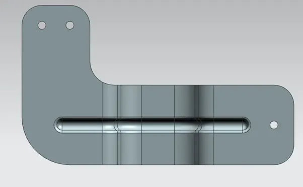
- Generate a normal cut-out command and make sure the bracket is in L-shape
- Generate a break corner command whose radius is 25mm on one of the 3 edges, another edge with radius 35mm and left top edge having radius 60mm as per the requirement.
- Generate 3 holes of 20mm diameter on the required place.
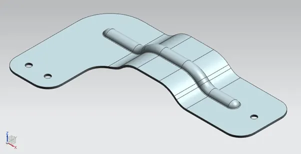
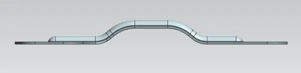
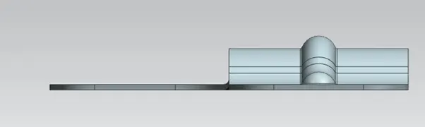
MODEL VIEWS OF BRACKET:
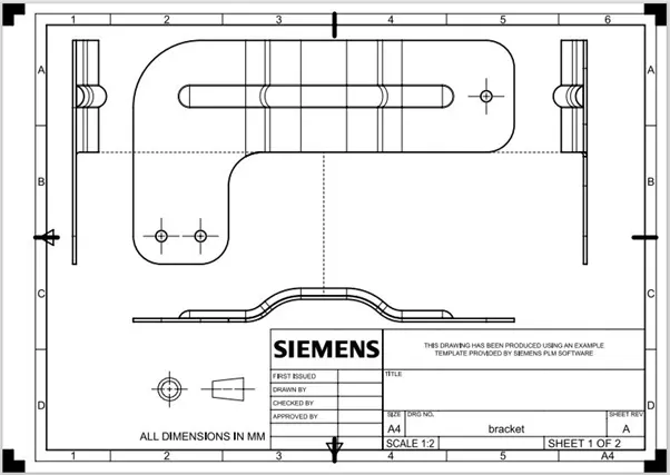
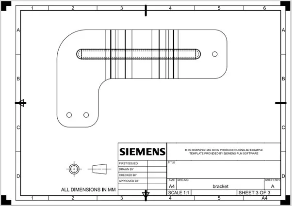
DRAWING SHEETS OF BRACKET:
CONCLUSION:
- This sheet metal bracket is completely designed on NX12.0 software in sheet metal work bench.
- Extra bead is designed to make the bracket stiff
- Holed are designed to mount on wall or any face.
- Finally the bracket is designed as per the requirement.