Advanced Sheet Metal Design Using NX Cad Challenge_6_Bracket
Bracket Design
OBJECTIVE
The main objective to design this is to familiar with different tools in NX CAD
software and what the process we are going to follow to get our output.
Introduction
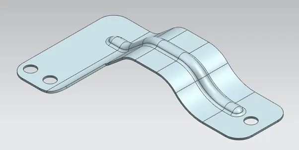
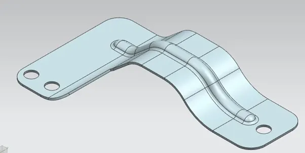
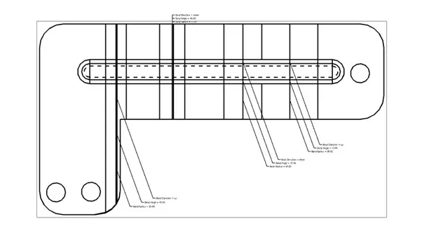
Here we are going to create bracket sheet metal using NC CAD software by using different tools and finally we are going to draft the file in a 2D format.
DESIGN METHODOLGY
Features Used
- Sketch
- Counter flange
- Normal cutout
- Break corner
- Unbend
- Re bend
- Bead
- Hole
- Flat pattern
sketch
It is the basis of a 3D model. You can create on any plane.
Counter Flange
It creates a base feature by extruding a sketch along a vector and adds material by sweeping a sketch along an edge or Chain of edge.
Normal cutout
It cuts material by projecting a sketch onto the model and then cutting perpendicular to the faces intersected by the projection.
Break corner
It rounds or chamfer the sharp corner of a tab or flange.
Unbend
It flattens a bend and the material adjacent to the bend.
Re bend
It restores the an unbend feature to its original bent state.
Hole
It adds a hole one or more in a solid body
Bead
It lifts the material along the counter of a sketch that simulates a stamping tool.
Flat Pattern
It creates flat pattern from the formed sheet metal part.
Procedure
- Open NXCAD create a new model .
- Create a sketch on XZ plane and extrude it by giving command counter flange.
- Draw a sketch by drawing some horizontal and vertical line on the extrude part and do a normal cut out.
- Now break the sharp edge corners by using” break corner” tab.
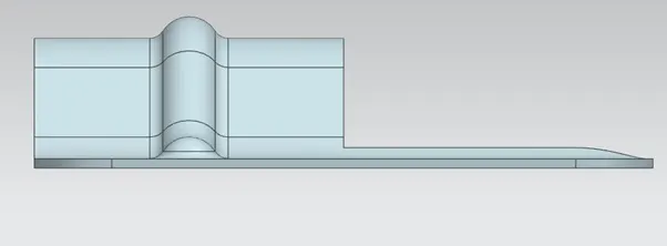
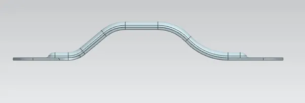
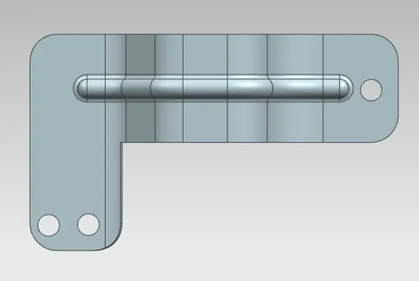
- Now unbend it and create a bead and holes by sketching a line and points respectively by using “bead” and “ hole” tab.
- Re bend it again.
Conclusion
We learn step by step procedure to create Bracket using different tools in Nx Cad.