Photo Realistic Rendering
TITLE - MODELING OF AMERICAN CHOPPER
OBJECTIVE
- To model all the chopper parts using solidworks.
- Assemble the components in a proper fixture.
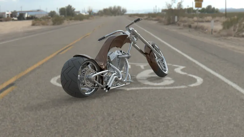
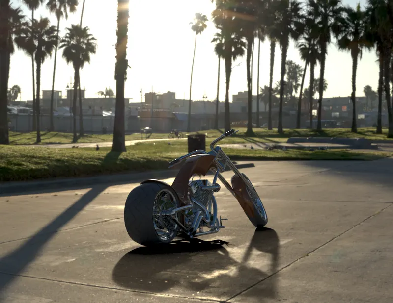
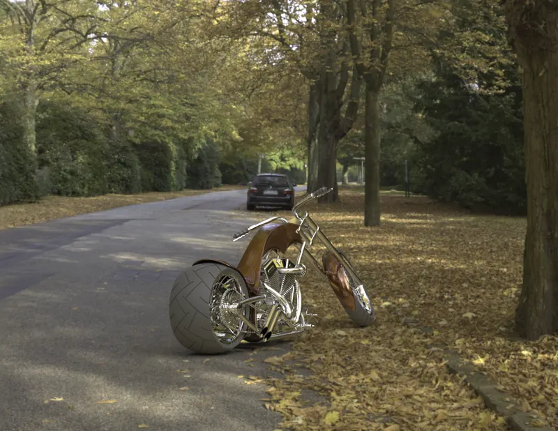
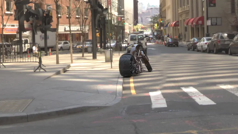
- Also to provide additional features like decals and, provide photorealistic view, renders using solidworks photoview 360 and visualize.
INTRODUCTION
- In this project solidworks is used to develop mechanical systems(parts) from beginning to the end. Initially this software is used for sketching and later modelling parts (such as transmission belt, pedal, kickstand, front fender, rear fender, front wheel, rear wheel, front fork, chassis, chain, gas tank, etc.
- Solid works visualization is used for making the model look realistic with better environment.
DESIGN METHOLODOGY/APPROACH
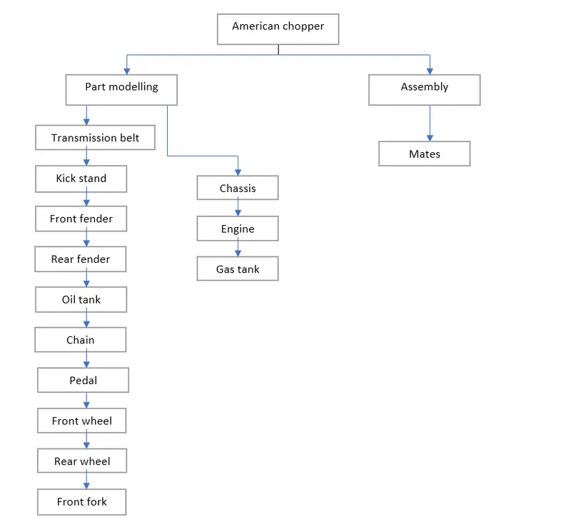
DESCRIPTION OF TOOLS AND FEATURES THAT ARE USED WHILE CREATING AMERICAN CHOPPER
Transmission belt
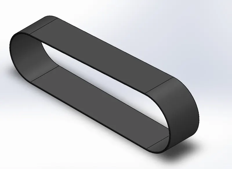
features used to create a transmission belt
- Sketch
- Offset
- Boss extrude
- Fillet
- Appearance
Sketch - It is a 2 Dimensional representation of the model. There are many sketch options(entities) available in solidworks such as line, circle, spline, rectangle, etc.
Offset - It is a handy entity used to place sketch over or inside the existing sketch by changing the offset distance.
Boss extrude - It is used to convert 2 dimensional object into 3 dimensional object. The direction of extrude can be given in both sides.
Fillet - It creates a round internal or external face on the selected edges. It can be given in both 2D and 3D format.
Process to create transmission belt
- First of all we need to create a part template and name it has LSW_part_mm make sure that this is in metric form, so that we can use this template for entire chopper modelling. Then change the front plane to front plane LSW and save it.
2. Now open the solidworks and select the new part file has LSW_part_mm and select front plane LSW.
3. Then create a 2D sketch, dimensions and relations are given to make a sketch fully define.
4. Then apply offset to the existing sketch by changing the offset distance and close the sketch.
5. Apply boss extrude to the 2D sketch to convert into 3D and use fillet on the edges of the transmission belt to make it smooth finish.
6. Close the sketch, rebuild and save the model as transmission belt.
Kick stand
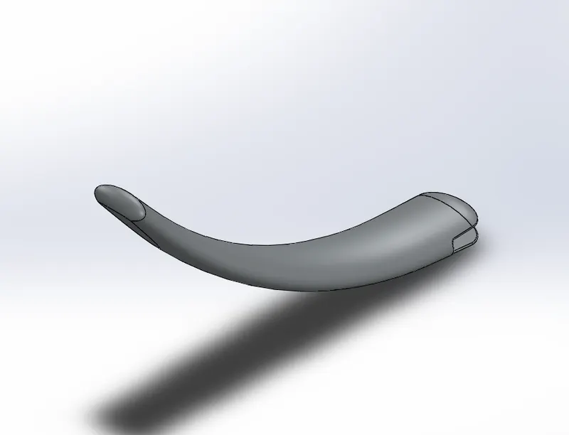
Features used to create kick stand
- Sketch
- Loft
- Dome
- Cut extrude
- Split
- Boss extrude
- Fillet
Loft - It is used to create a loft by selecting two different selected sketches along with centerline sketch as reference.
Dome - It is used to create a rounded vault on any selected face typically with circular or elliptical base.
Cut extrude - It is used to remove material from 3D object and is opposite to boss extrude
Split - It is used to remove unwanted material between the two intersecting objects and makes it look good.
Front fender
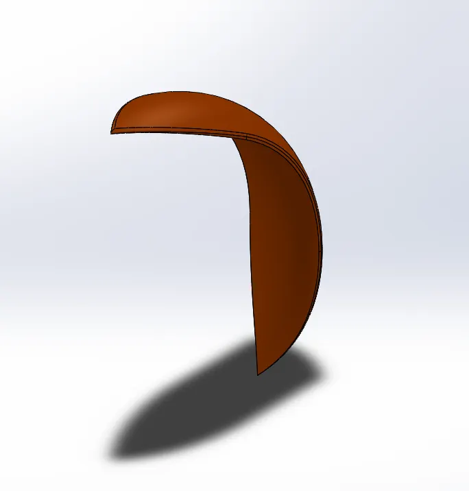
Features used to create front fender
- Sketch
- Revolve
- Split
- Fillet
- Trim entities
Revolve - To create a revolve we should create two different profiles and a centerline to make it reference as axis of revolution.
Trim - It is very useful to remove unwanted sketches from the sketch entity and the entity can also be extended by using extend.
Rear fender
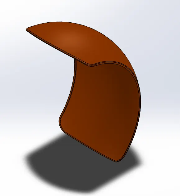
Features used to create rear fender
- Sketch
- Revolve
- Split
- Fillet
- Shell
Shell - It is used to change the thickness of body.
Oil tank
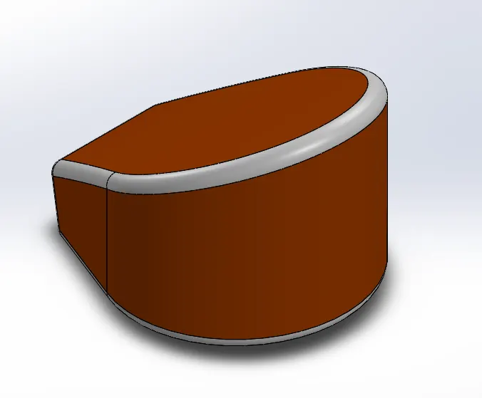
Features to create oil tank
- Sketch
- Boss extrude
- Combine
- Fillet
- Shell
- Appearance
Combine - It is used to combine two or more different bodies intersecting each other to make a single body.
Appearance - It is used change the colour or appearance of the object to our requirement in order to get a better look.
Chain
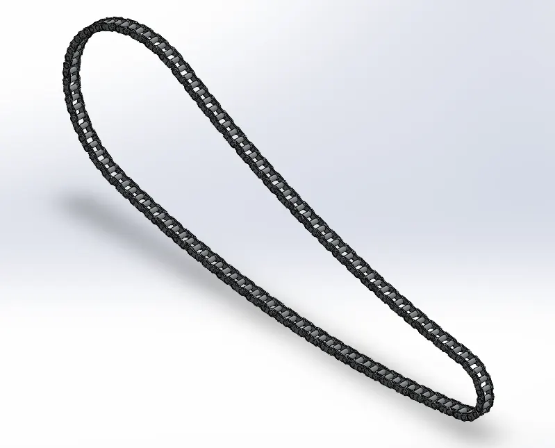
Features to create a chain
- Sketch
- Trim entities
- Boss extrude
- Fillet
- Blocks
- Circular Pattern
- Mirror
Circular Pattern - Curve driven circular pattern used to create a pattern along a 3D curve or on a plane. By taking a taking 3D curve or entity as a circular path reference we can create a multiple blocks along the curve.
Mirror - It is used to make the mirror of preselected profile .
Blocks - They are generally used to save a sketch as a file link and we can use that link multiple times without creating the sketch again.
Pedal
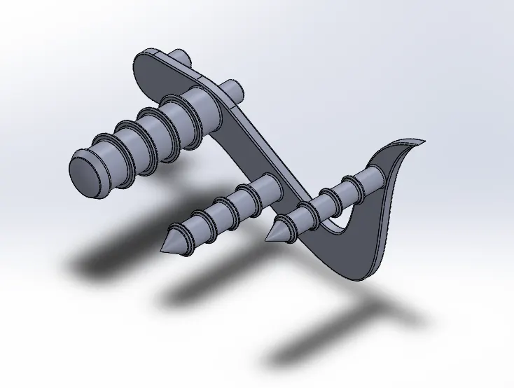
Features to create a pedal
- Sketch
- Boss extrude
- Fillet
- Revolve
- Dome
- Chamfer
- Linear pattern
- Revolve
Revolve - It is used to make a 3D revolve of the selected sketch by taking centerline as axis of revolution.
Chamfer - It is used to create a flat surface on the edges. It can be done in two ways by changing distance and angle distance.
Linear pattern - It is same as circular pattern, but it is used to create a multiple profiles of selected profile along the linear path.
Front wheel
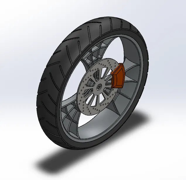
Features to create a front wheel
- Revolve
- Boss extrude
- Cut extrude
- Cut revolve
- Circular pattern
- Combine
- Fillet
- Chamfer
Cut revolve - It is used to remove a material along the revolved surface.
rear wheel
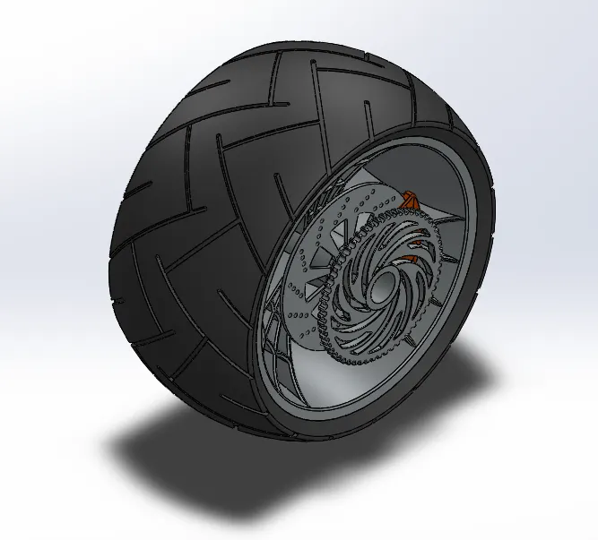
Features to create a rear wheel
- Sketch
- Revolve
- Cut extrude
- Boss extrude
- Circular pattern
- Combine
- Cut revolve
- Fillet
- Chamfer
- Planes
Planes - To create a new plane we should go to reference geometry and select plane, then select any existing sketch on which we want to create a new sketch.
Front fork
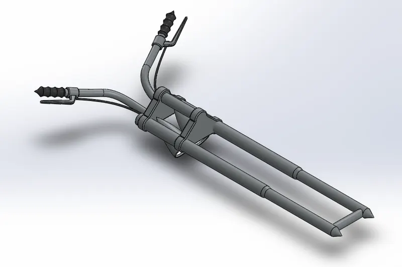
Features to create a front fork
- Sketch
- Revolve
- Boss extrude
- Fillet
- Linear pattern
- Cut extrude
- Dome
- Cut revolve
- Projected curves
- Planes
- Combine
- Sweep
Projected curve - It is a 3D curve which is obtained by creating two or more sketches on different planes. It is very useful to make a complex curve in solidworks rather than going for 3D curve.
Sweep - It is a 3D feature used to make a closed profile along an open or closed path to form a solid body.
Chassis
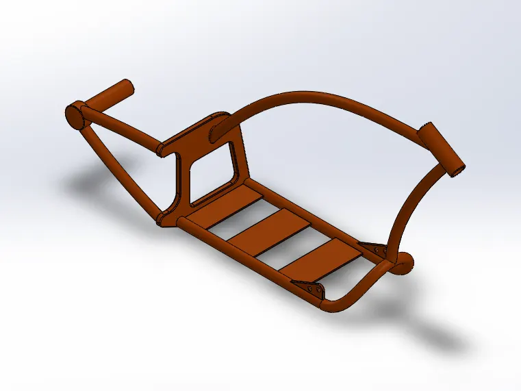
Features to create a chassis
- Blue print sketch
- Sketch
- Projected curve
- Sweep
- Mirror
- Boss extrude
- Cut extrude
- Chamfer
- Fillet
- Plane
- Dome
- Split
- Revolve
- Combine
- Mirror
Blue print sketch - It is a reference picture used in solidworks. By taking this as a reference we can create a sketch and later we make sketch as a 3D profile.
Engine
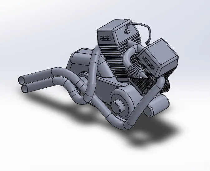
Features to create a engine
- Blue print picture
- Sketch
- Boss extrude
- Fillet
- Revolve
- Plane
- Circular pattern
- Dome
- Cut extrude
- Chamfer
- Fillet
- Linear pattern
- Sweep
- Mirror
- Combine
- Curves
- Composite curve
- Split
- Circular pattern
Composite curve - It is a 3D curve produced from two different curves( combining projected curve and other curve).
Gas tank
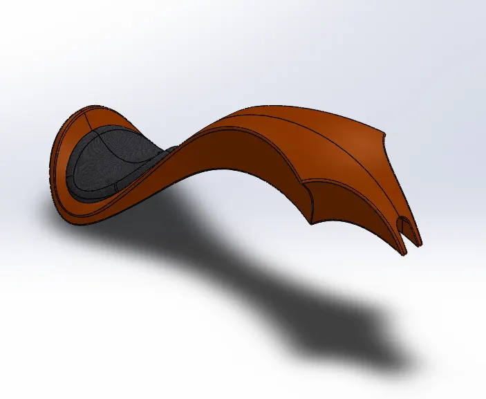
Features to create a gas tank
- Blue print sketch picture
- Plane
- Surface sweep
- Surface trim
- Curves
- Surface loft
- Boundry surface
- Surface knit
- Mirror
- Split
- Surface extrude
- Fillet
- Cut sweep
- Shell
Surface loft - This surface loft is produced by creating different 3D curves.
Surface trim - It is used to remove a material from the surface.
Surface sweep - It is used to create a closed surface along the surface.
Surface knit - It is used to reduce the gap between the two surfaces .
ASSEMBLY
It is a process of combining group of components together in one place.
Mates
Mates are used to give geometrical relations to the assembly parts.
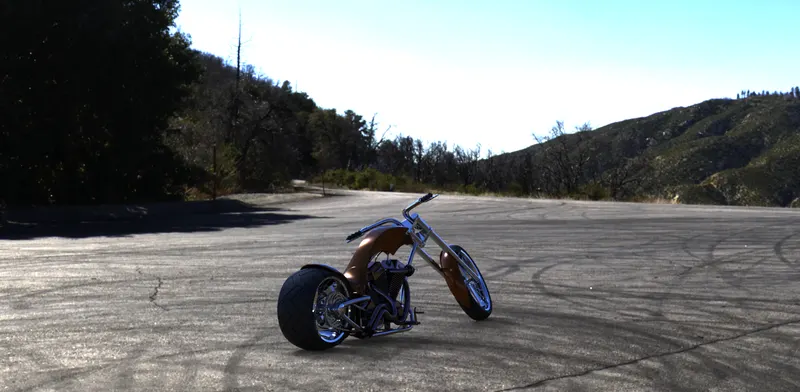
Rendering are used to create realistic image of the photorealistic model. It can be done in two ways.
- Photoview 360 and
- Solid works visualize
In photoview 360 we can add additional features like decals to make the model look realistic.
In visualize the assembly can get more realistic view and we can add many background environment(features) to make it better.
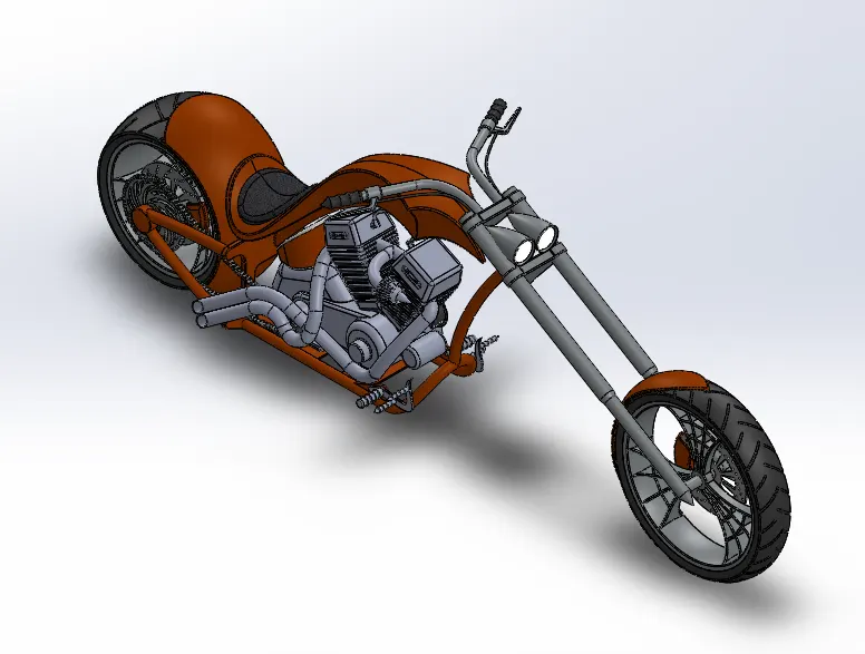
ASSEMBLY
Front view
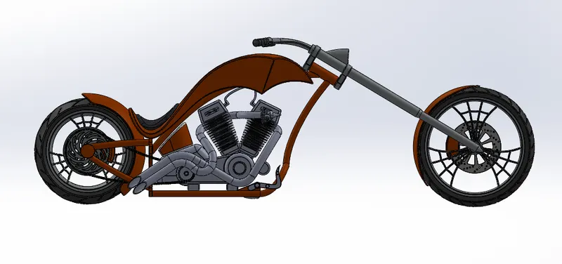
Side view
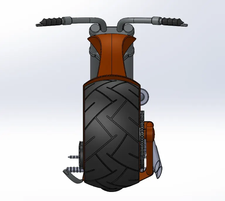
Isometric view
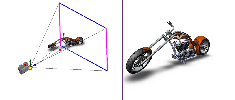
Camera set up view
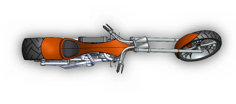
Top view
Rendered images
Conclusion
- All the chopper parts are modelled with fully defined by using dimesions and relations.
- Parts of American chopper are assembled in a proper arrangement.
- Renders and visualization are used to get a complete photorealistic view.