Advanced Sheet Metal Design Using NX Cad Challenge_6_Bracket
TITLE – MODELLING OF SHEET METAL BRACKET
OBJECTIVE
The main objective of this project is to design the sheet metal bracket using NX cad.
INTRODUCTION
NX sheet metal provides set of tools with in NX design environment that allows for simple and fast design of sheet metal parts, that depend on their design and manufacturing process. Using NX sheet metal formed and unformed representations of parts are created closely following the industry workflows and best suitable for bending calculations, tooling and other sheet metal features.
DESIGN METHODOLOGY
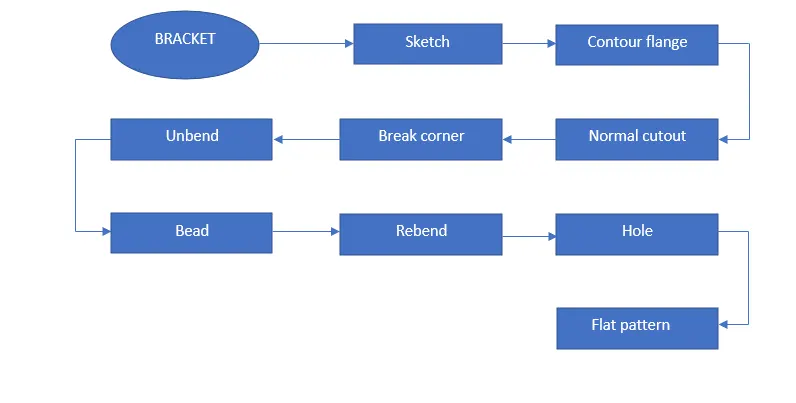
DESCRIPTION OF TOOLS AND FEATURES THAT ARE USED WHILE CREATING BRACKET
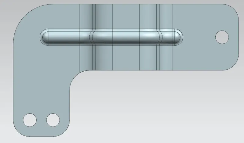
Bracket
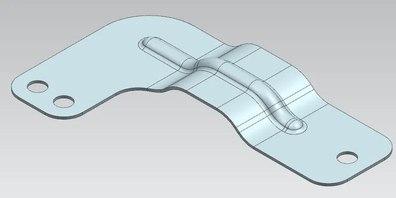
Features used to create bracket
- Sketch
- Contour flange
- Normal cutout
- Break corner
- Unbend
- Bead
- Rebend
- Hole
- Flat pattern
Sketch - It is a 2D representation of the part with respect to plane.
Contour flange - It is used to create a base feature by extruding a sketch along a vector, or adds material by sweeping a sketch along an edge or chain of edges.
Normal cutout - It cuts material by projecting a sketch onto the model and then cutting perpendicular to the faces intersected by the projection.
Break corner - It is used to create a round fillet or chamfer to the sharp edge to form a smooth finish.
Unbend - It flattens all the bends and made adjacent to the selected stationary face or edge.
Bead - It is used to create a contour of the sketch by lifting a material along the sketch that result as stamping tool.
Rebend - It is used to restore the unbend feature to its previous bend state, along with any features that are added after unbend feature.
Hole - It adds a hole to one or more solid bodies in a part or assembly.
Flat pattern - It is used to create a flat pattern of the final obtained sheet metal part.
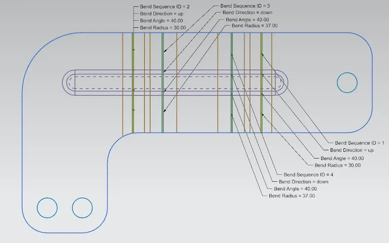
Process to create a bracket
- Open the NX and open the new sheet metal file.
- Draw a sketch on XZ plane and apply contour flange along the created sketch and then apply normal cutout by projecting a sketch onto the model.
- Apply break corner to the sharp edges to make it smooth finish.
- Apply unbend feature to the formed sheet metal part and then create a new sketch on the flat pattern.
- Then make bead along the new sketch and then rebend the sheet metal part to its previous bend state.
- Apply few holes on the sheet metal, and finally make flat pattern on the formed sheet metal to convert it into a flat portion.
- Save the file as bracket.
Bracket
Front view

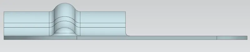
Side view
Isometric view
Top view
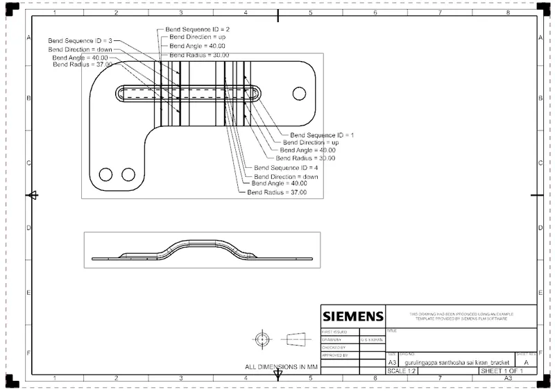
Drawing sheet
Conclusion
Thus, the sheet metal bracket is successfully formed as per the given guidelines by using various tools in NX cad.