Advanced Sheet Metal Design Using NX Cad Challenge_2_Box Assembly
TITLE – MODELLING OF BOX ASSEMBLY
OBJECTIVE
- The main objective of this project is to design a sheet metal box assembly using NX cad.
INTRODUCTION
- Sheet metal is a metal forming with a small thickness varying from 0 to 6mm which is made thin and flat by using different mechanical operations.
- NX Creates sheet metal component models using specific, feature-based tools for tabs, flanges and other necessary features. Sheet metal tools can be used to generate accurate flat pattern data for downstream applications from solids, sheets and wireframe geometry.
DESIGN METHODOLOGY
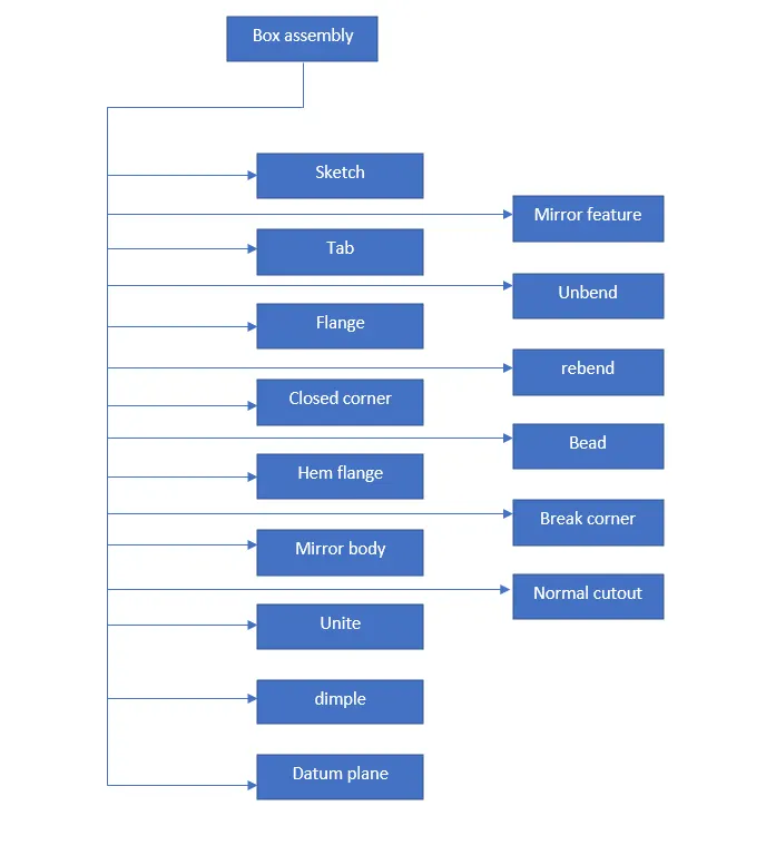
DESCRIPTION OF TOOLS AND FEATURES THAT ARE USED WHILE CREATING BOX ASSEMBLY
BOX ASSEMBLY
Features used to create box assembly
- Sketch
- Tab
- Flange
- Closed corner
- Hem flange
- Mirror body
- Unite
- Dimple
- Datum plane
- Mirror feature
- Unbend
- Rebend
- Bead
- Break corner
- Normal cutout
Sketch - The sketch is the most fundamental element in any design of sheet metal component. To apply any feature to sheet metal, sketch is the most important and it can be represented as the parent sketch. Sketches like curves, lines, circles, etc.
Tab - It is the first feature in any sheet metal component design. It is used to add a material to a planar surface by extruding a sketch along a direction of given thickness.
Flange - It is used to create a flat flange(flat surface or angular surface) at an angle to a planar surface and adds the bends between the two sides.
Closed corner - This feature is used to fill the gaps or unfilled portion of the body.
Hem flange - It is used to modify the model by folding the edge of a sheet metal flange over onto itself for the purpose of safe handling or to increase the edge stiffness.
Mirror body - It is used to copy a body or mirror the body across the plane taken as reference.
Unite - It is used to combine the volume of one or more bodies to form a single body.
Dimple - It is used to lift an area of the model inside the sketch and represents as stamping tool.
Datum plane - It is used to create a reference plane used to construct other features.
Mirror feature - It is same as mirror body, but here it mirrors the feature instead of body.
Unbend - It flattens all the bends and made adjacent to the selected stationary face or edge.
Rebend - It is used to restore the unbend feature to its previous bend state.
Bead - It is used to create a contour shape according to the sketch in required direction with required punch radius. It is similar to dimple, that makes the impression along the direction of sketch.
Break corner - It is used to create a round fillet or chamfer to the sharp edge to form a smooth finish.
Normal cutout - It is used to remove a material or create a gap of the selected sketch.
Process to create a box assembly
- Open the NX 12 software and select sheet metal as a new file, then create a sketch and apply tab.
- Apply flanges to the edges of the tab, and apply close corner and make sure that the gaps are filled(closed).
- Execute 4 more flanges to the existing edges of the flanges and apply hem flanges to its edges.
- Mirror is applied to copy or mirror the surfaces to other side, unite feature is applied to make the parts as a single body. Then sketch is created on one side of flange surface and dimple is applied to the sketch to get contour of that sketch.
- This dimple feature is copied to other side of flange using mirror option, and one more dimple is created on the bottom of the tab.
- Then unbend and rebend the sheet metal and apply bead feature to the new sketches created on the bottom of the tab.
- Mirror is applied to get 3 more bead features on the bottom of the tab, and 6 more hem flanges are applied on the top edges of the side flanges.
- Create a datum plane on top plane so that we can create a new sketch on it and apply tab to that sketch, and flanges are applied to the new tab.
- Then create a new sketch on right plane and apply break corner to the edges of the sketch to make a round fillet and apply 2 flanges to the top edge and apply hem flange to that flange edge and unbend the sketch. Then remove a material from the sketch using normal cutout and then rebend it to restore its previous bend state. Mirror these features to other side as well.
- Repeat the step 9 on the tab on top plane to make a complete box assembly and save the file as box assembly.
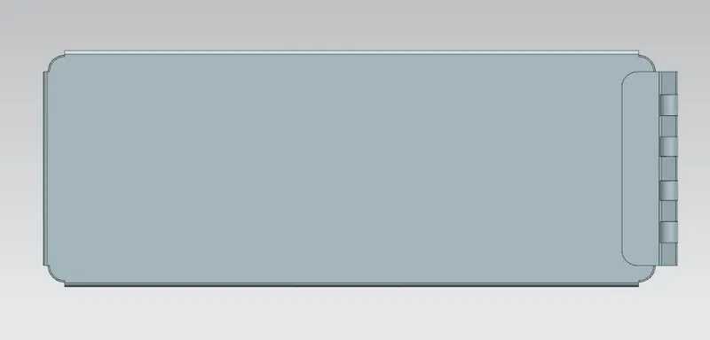
Box assembly
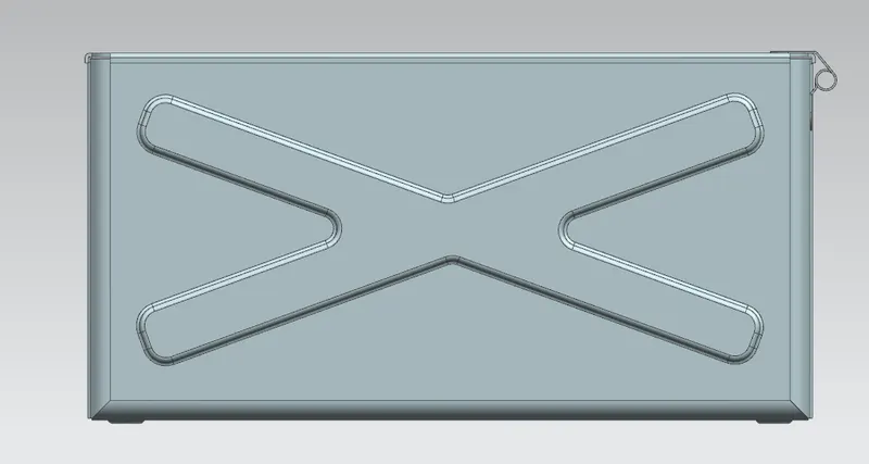
Front view
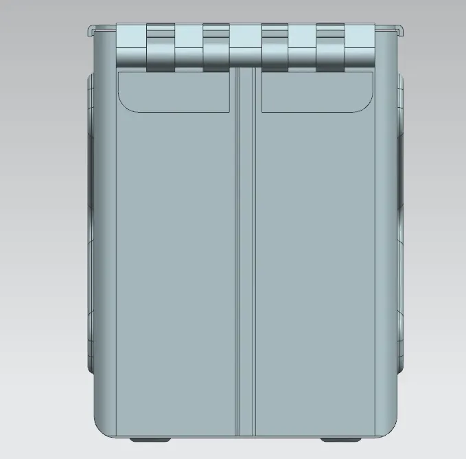
Side view
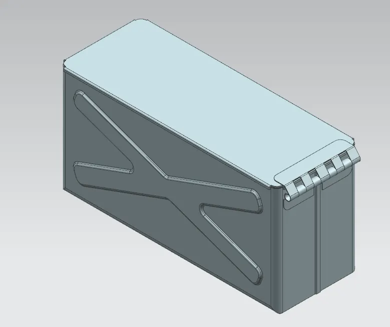
Isometric view
Top view
Conclusion
- Hence the model was successfully designed and dimensioned with proper constraints as per the given guidelines using NX 12.