Perform Batchmeshing on Fender & headliner components and assigning non-linear material & property card in Hypermesh.
Aim: To Perform Batchmeshing.
Objective:
- Perform Batchmeshing on Fender and headliner components with the given criteria.
Quality Criteria for Fender Component: -
Target Element Length = 5 Units for Fender Component
|
S.no. |
Quality Criteria |
Value |
|
1 |
Aspect Ratio |
5 |
|
2 |
Skewness |
45 |
|
3 |
Warping |
15 |
|
4 |
Taper |
0.5 |
|
5 |
Min. Length |
2 Units |
|
6 |
Max. Length |
8 Units |
|
7 |
Min angle Quad |
45 |
|
8 |
Max angle Quad |
135 |
|
9 |
Min angle Tria |
20 |
|
10 |
Max angle Tria |
120 |
|
10 |
Tria % |
10 |
Parameter File for Fender Component: -
Use the “Crash 5mm” parametric file located in Local Disk ‘C’ → Program Files → Altair → 2022-edu → hwdesktop → hm → Batchmesh.
Criteria File for headliner Component: -
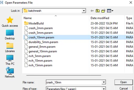
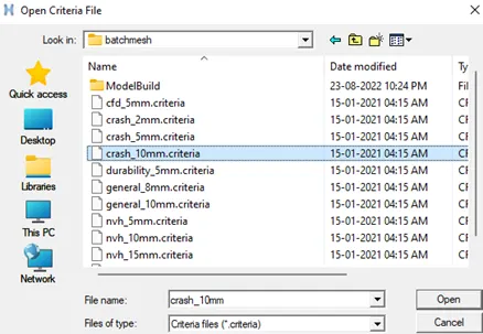
Use the “Crash 10mm” Criteria file located in Local Disk ‘C’ → Program Files → Altair → 2022-edu → hwdesktop → hm → Batchmesh.
Parameter File for headliner Component: -
Use the “Crash 10mm” parametric file located in Local Disk ‘C’ → Program Files → Altair → 2022-edu → hwdesktop → hm → Batchmesh.
- Assign the non-linear material property Steel to them. No need to check and fix the components for feature capturing, mesh flow, and quality criteria.
NOTE: Use Radioss profile for assigning the material properties
Introduction:
Automatic/ BatchMesher / Mesh Adviser is a tool that can perform geometry cleanup and automeshing (in batch mode) for given CAD files. BatchMesher performs a variety of geometry cleanup operations to improve the quality of the mesh created for the selected element size and type. Cleanup operations include: equivalencing of "red" free edges, fixing small surfaces (relative to the element size), and detecting features.
BatchMesher also performs specified surface editing/defeaturing operations such as: removal of pinholes (less than specified size), removal of edge fillets, and addition of a layer of washer elements around holes.
All user-defined criteria determine the quality index (QI) of a model. The QI value is used to assess the potential of each geometry clean-up and meshing tool, and apply them accordingly. QI optimized meshing and node placement optimization are performed to obtain the best quality meshing. Final results are stored in a HyperMesh database file.
1. Steps Taken for meshing and assigning material & property card to Fender Model:
- Import Model:
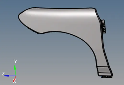
2D Topo View of the geometry:
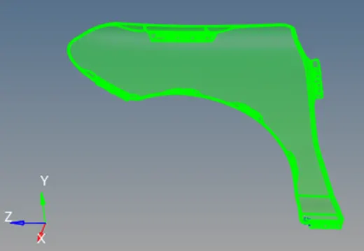
Topology view shows that the geometry is a solid.
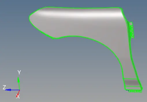
Geometry in Topo view after removing solids:
- Duplicating the Geometry:
For comparison purpose we will duplicate the current component by right clicking and selecting the component.
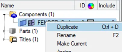
Then then we will duplicate the model surface to the duplicated component.
For this, go to, Tools -> Organize

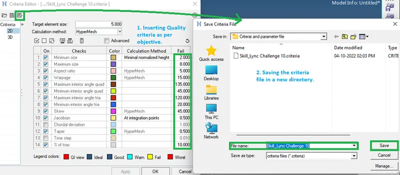
- Inserting quality criteria as per objective:
In the menu bar, go to, Preferences -> Criteria file settings.
Then select the above-mentioned criteria and save the file to a new directory.
- Meshing the model:
Go to, 2D -> Automesh ->batchmesh/QI optimize

Select the parameters file and saved criteria file. Then select the displayed surface and click on mesh.
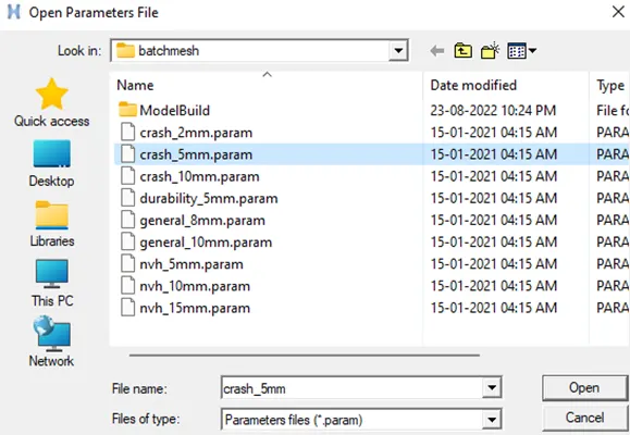

The Parameter file clean up the geometry as per our requirement. And the Criteria file meshes the geometry as per our quality criteria.
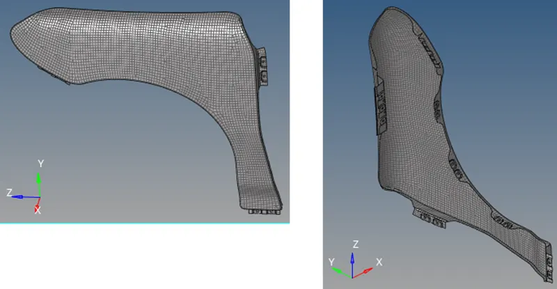
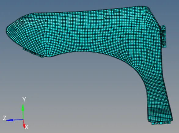
Meshed model is as shown below:
- Creating Material card and assigning it to the model:
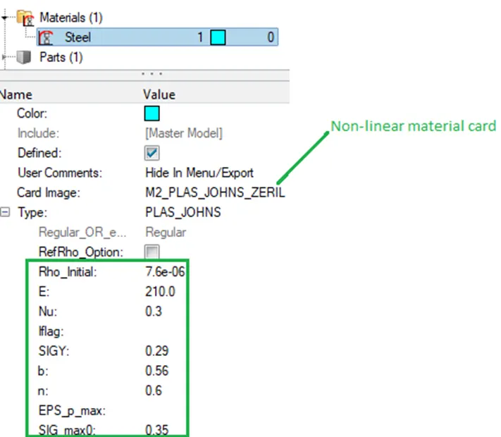
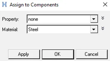
To assign the non-linear material card right-click on the component panel and select,
create -> material
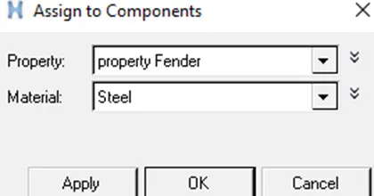
To assign property to a component, select the component, click on ‘property’ and then select the property. Or right click the component, select assign and then assign the property.
Viewing the component, By mat
- Creating Property card and assigning it to the model:
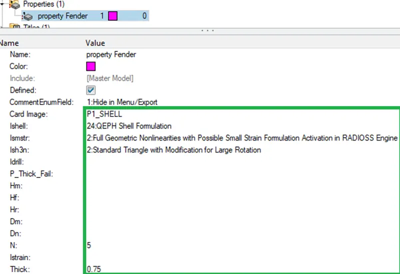
To create property card right-click on the component panel and select,
create -> property
Assigning the property to the model
Viewing the component, By Prop
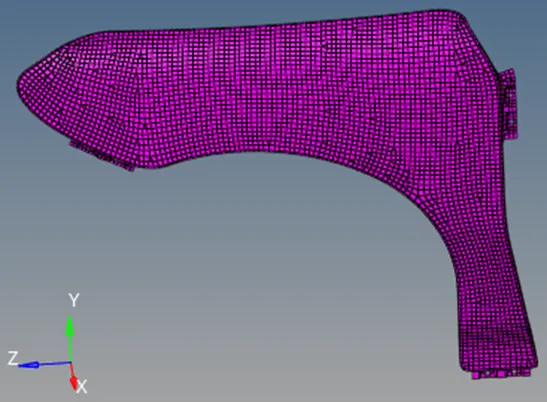
2. Steps Taken for meshing and assigning material & property card to Fender Model:
- Import Model:
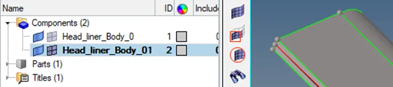
2D Topo View of the geometry shows that the model has no solid, so we have a shell model.
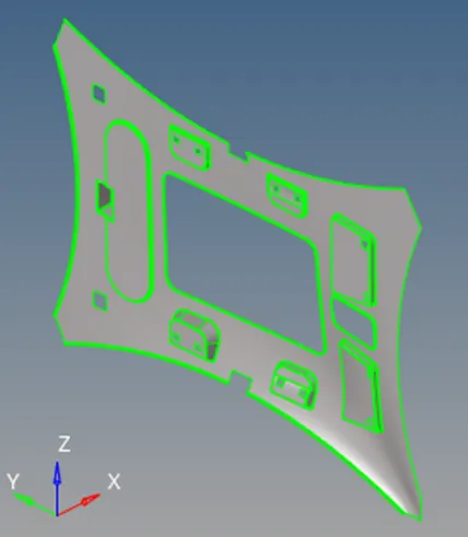
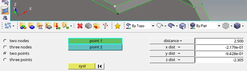
The thickness of the model is 2.5mm.
- Duplicating the Geometry:
For comparison purpose we will duplicate the current component by right clicking and selecting the component.

Then then we will duplicate the model surface to the duplicated component.
For this, go to, Tools -> Organize

- Meshing the model:
Go to, 2D -> Automesh -> batchmesh/QI optimize
Select the parameters file and saved criteria file. Then select the displayed surface and click on mesh.

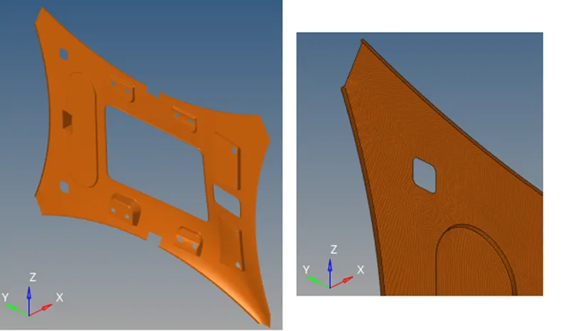
On comparing we can see that the middle surface has been extracted:
Meshed model is as shown below:
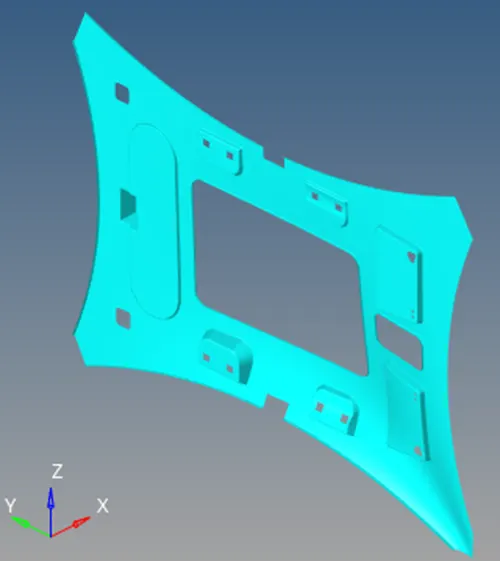
- Creating Material card and assigning it to the model:
To assign the non-linear material card right click on the component panel and select,
create -> material
To assign property to a component, select the component, click on ‘property’ and then select the property. Or right click the component, select assign and then assign the property.
Viewing the component, By mat
- Creating Property card and assigning it to the model:
To create property card right-click on the component panel and select,
create -> property
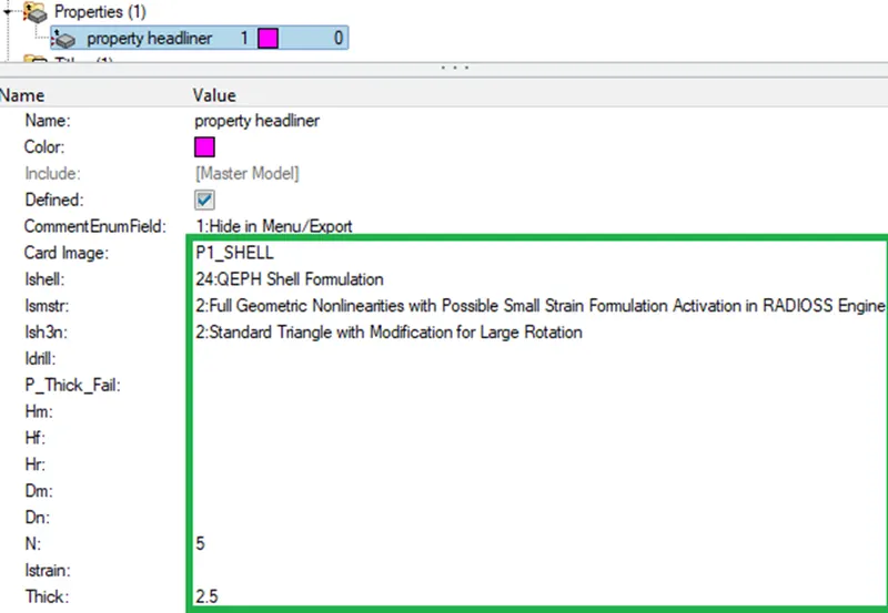
Assigning the property to the model
Viewing the component, By Prop
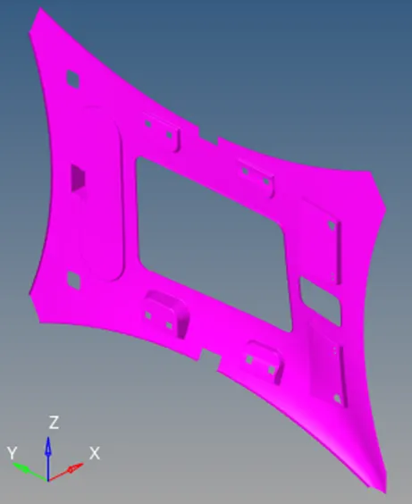
Conclusion:
- Batchmeshing, in hypermesh is utilised for meshing a component quickly by giving Parameter and criteria file as input. The batching will extract mid-surface and mesh it with the given quality criteria.
- For a complex geometry, batchmeshing will not give proper mesh flow and quality. So, the batchmeshing should be utilised only when the mesh is required in a short time and also when the quality of the mesh is not a priority.
- For Non-Linear Material Card in Radioss, we need to select card Image as “M2_PLAS_JOHNS_ZERIL”.
For Steel material following values are used:
Initial Density (Rho_initial) : 7.6e-06,
Young Modulus (E) : 210,
Poisson Ratio (Nu) : 0.3,
Yield Stress (SIGY) : 0.29,
Hardening Parameters (b) : 0.56,
Hardening Exponent (n) : 0.6,
Failure Plastic Strain (EPS_p_max) : 1e+30,
Minimum Stress (SIG_max0) : 0.35
- For setting up property, we have selected
Property data Card Image as “P1_SHELL “,
Solid Flag (Ishell) : 24:QEPH shell formulation,
Flag for shell small strain formulation, (Ismstr) : 2:Full Geometric nonlinearities with possible small strain formulation activation in RADIOSS Engine,
Flag for 3 node shell element formulation (Ish3n) : 2:Standard triangle (CO) with modification for large rotation,
Number of Layers (N) : 5 Shell,
Thickness (Thick) : as per given data.
Reference: