Modelling of 25 storey building with the specified properties using ETABS
AIM: To model a 25 storey building on ETABS with structural properties as specified below. Ground floor or plinth floor level can be taken at a height of 1.5 meters from the base. Each of the successive 25 storeys has a storey height of 3 meters.
Structural Element Sizes
- Beam: 300 × 400 mm
- Column: 800 × 800 mm
- Slab: 150 mm thick
Material Properties
- Grade of Concrete: M30
- Grade of Steel Reinforcement Bar: Fe415
Loading
- Dead Load on beams from infill wall: 10 kN/m (Let us assume the same for roof floor in view of parapet)
- Live load on floor: 3 kN/m2 (Let us assume the same for roof floor)
- Buildings are assumed to be pinned at the base
- All columns in all storey are of the same size
- All beams in all storeys are of the same size
- Building is located on Soil type-II and in Zone-III. Assume other factors if required.
To carry out the following exercises:
- Check if the translational fundamental natural period of vibration in both the x and y direction is approximately: TX1= 4.4 second TY1= 4.2 second
- Check if the following provision in Table 5 of IS 1893 (part 1) – 2016, on torsional irregularity satisfied
- Check if the two provisions of clause 7 in Table 6 (shown below) of IS 1893 (part 1) – 2016, regarding vertical irregularity is satisfied
- Check if provision on inter-storey drift limitations in clause 7.11.1.1 satisfied.
PROCEDURE:
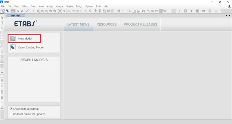
- Open ETABS software and click on the new model option in the start page or file menu
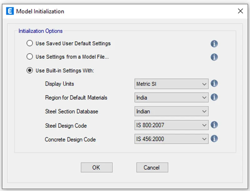
- Now in the model initiation window select Metric SI as display units, also Region, Design codes which are to be used were selected and then click OK.
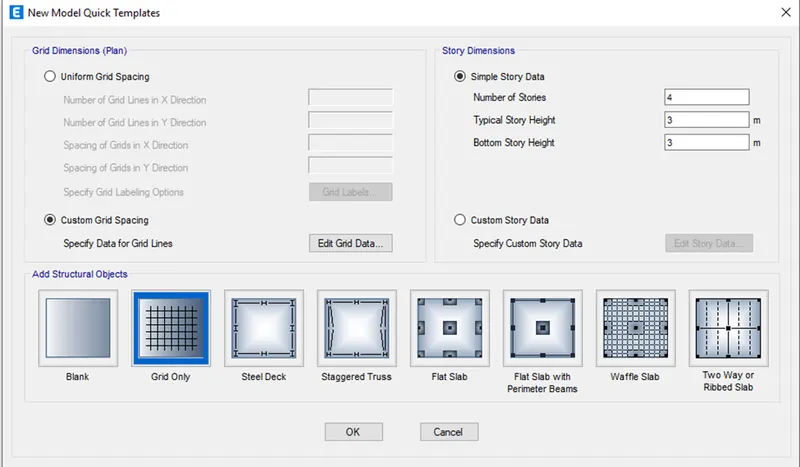
Creating grids and stories - Select custom grid spacing from the new model quick templates window to draw grid lines according to the spacing provided in the problem
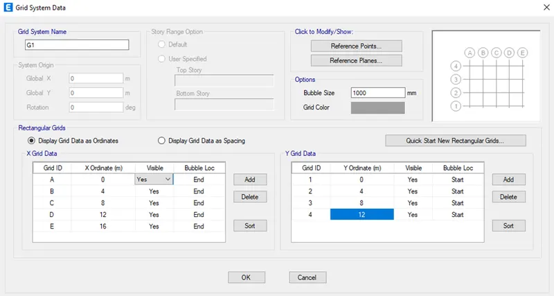
- The grid data along both X and Y direction are entered to draw grids as pes data provided in the question.
- To add more grids click add button and enter the cumulative distance
- Click ok to finish grid system data
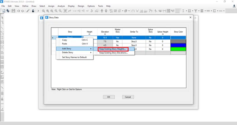
- Click on custom storey data to input storey data
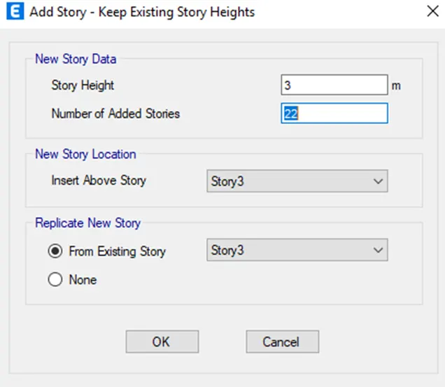
- Plinth level is at 1.5-meter from the base. Each of the successive 25 storeys has a storey height of 3 meters.
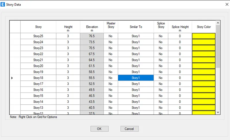
- Now input the storey details as given in question and story 1 was selected as the master story and was applied to rest story from 2nd story to 25 storey and then click OK.
- After entering all data click OK
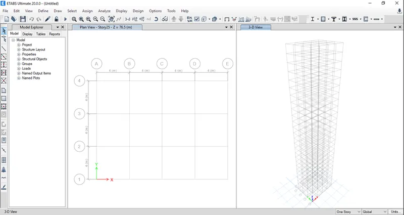
- The plan and 3D view is shown on the image below.
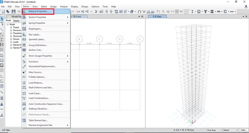
Defining material properties - To define the material properties of elements, go to define menu and then select material properties.
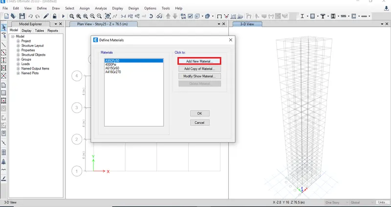
- Click add new material to define material property
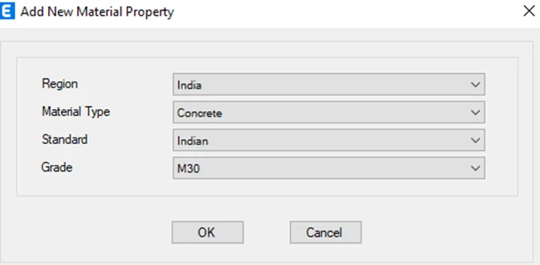
- The grade of concrete was selected and click ok.
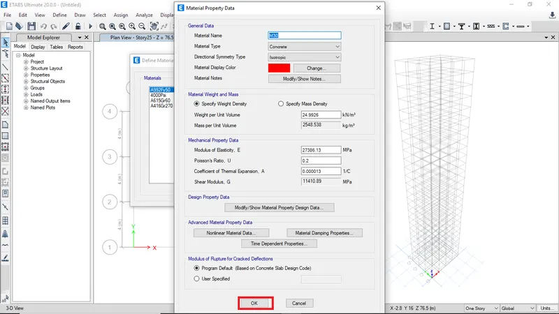
- Select steel reinforcement and grade
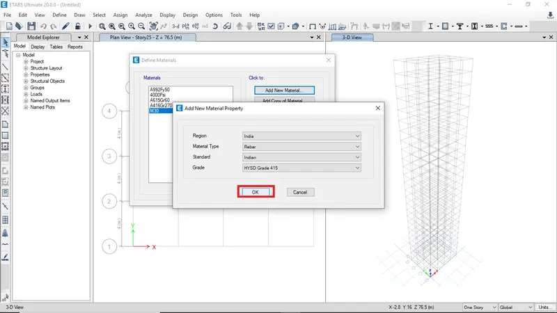
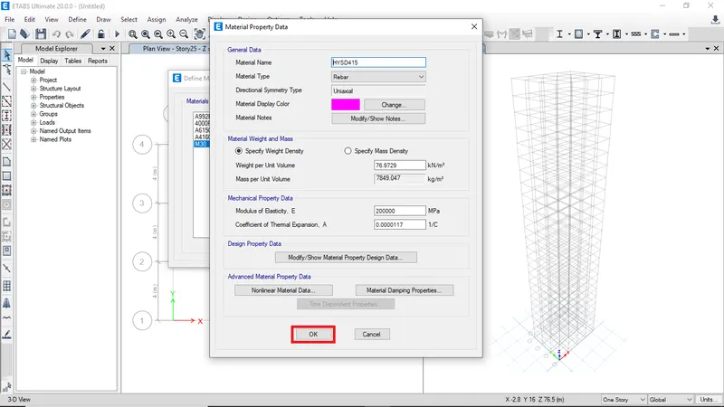
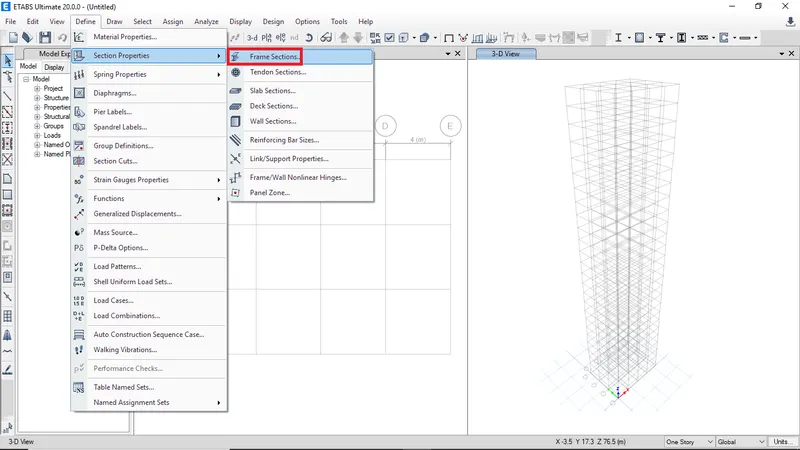
Defining frame and slab sections - To define frame properties goto define and select section properties then select frame sections
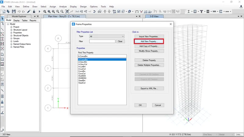
- Click on add new property to define beam properties
- Select rectangular section then click ok
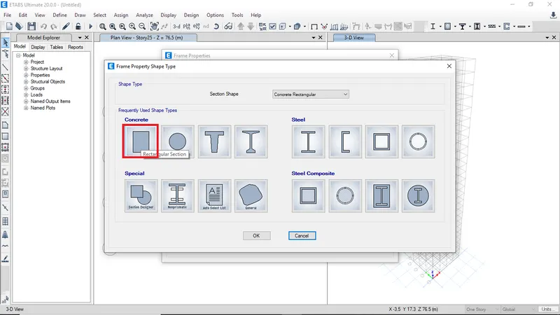
- Specify the beam depth and width then click on modify reinforcement to edit reinfoecement data
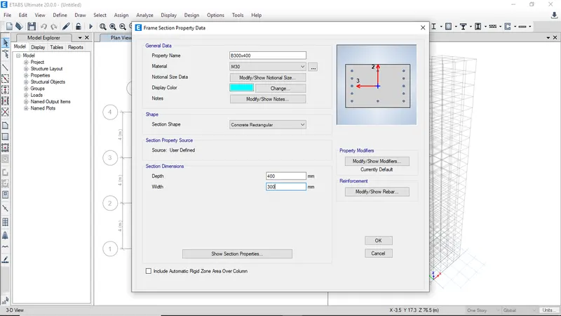
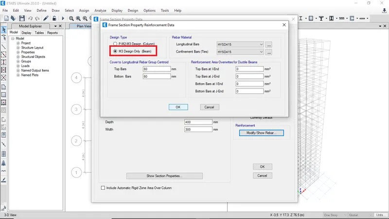
- Select design for beam and specify rebar material for longitudinal and confinement bars then click ok
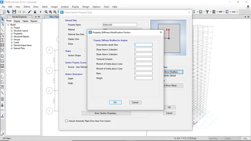
- Click on modify to edit the properties of frame section
- To define column section click on add new peoperty
- Then select rectangular section and provide column width and depth as 800 x 800
- Then click on modify reinfoecement
- Select column design and specify rebar material and click ok
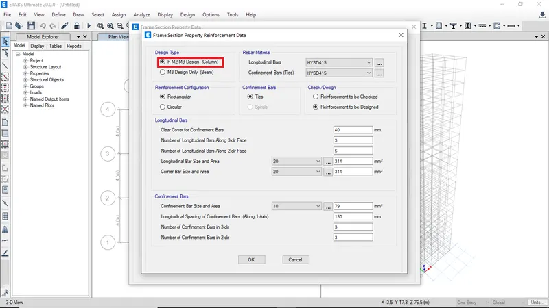
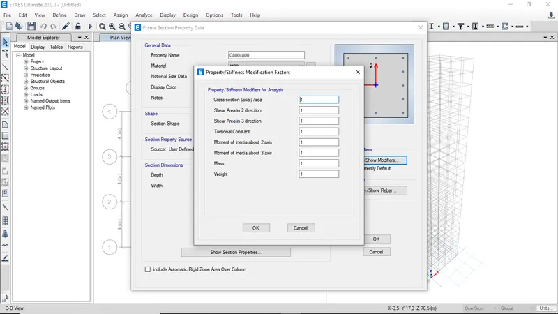
- Click on modify property to mofify column section properties
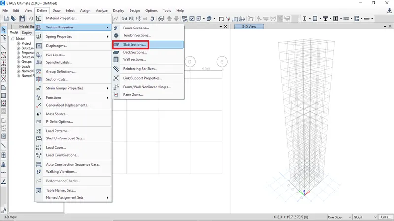
- To define slab section properties goto section properties in define menu then click on slab sections
- Click on add new property to define slab properties
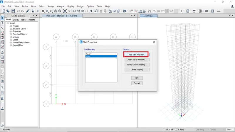
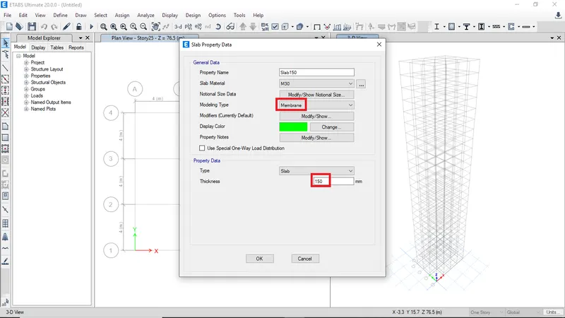
- Provide property name and select modeling type as membrane
- Enter slab thickness as 150 mm than click ok
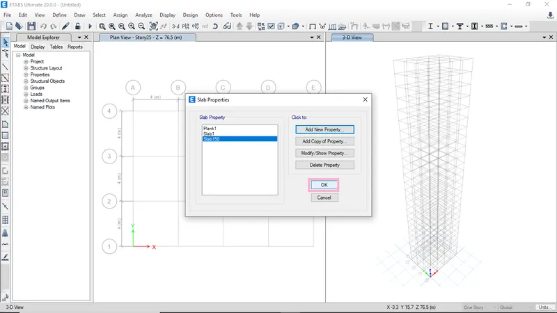
- After defining slab properties click ok
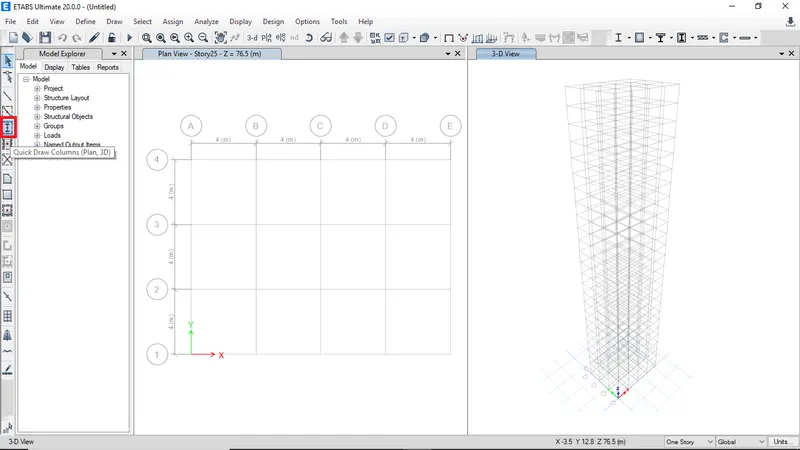
Drawing column, beam and slabs - Click on quick draw columns and select column property as C800x800
- And make sure draw mode switched to all stories to replicate column in all stories
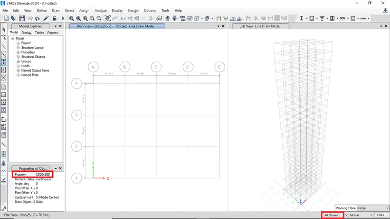
- Drag the cursor in which whole grids are enclosed within to create columns at grid joints
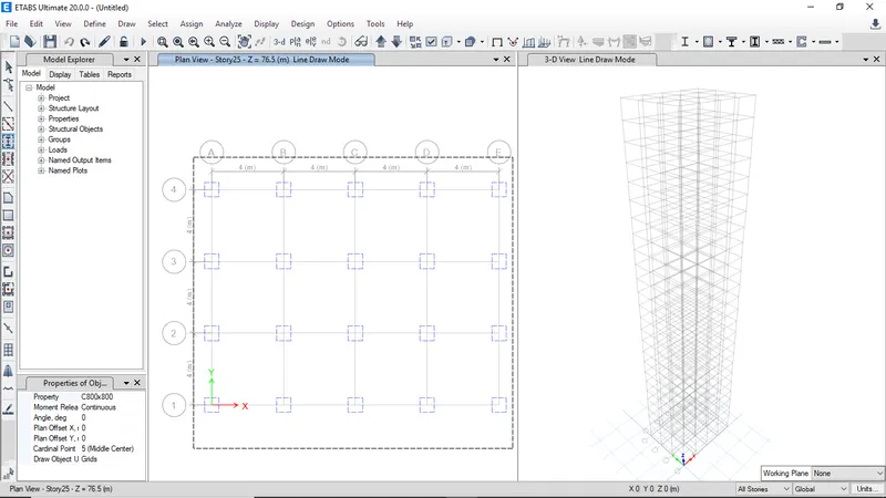
- The columns are created in all storyes
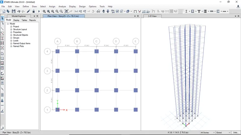
- Click on quick draw beams to draw beams at all the grids
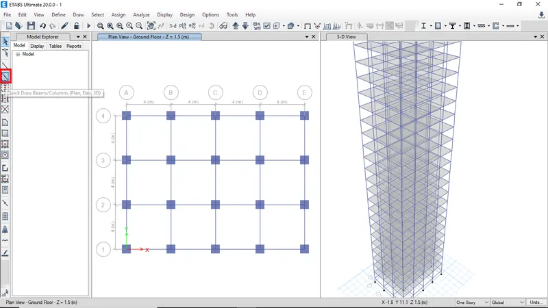
- Select the beam property B300x400 and switch to all stories before creating beams
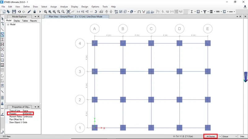
- Click on quick draw floor
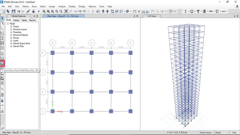
- Select slab property slab150 and switch to similar storeys then click on each grid box to create floors
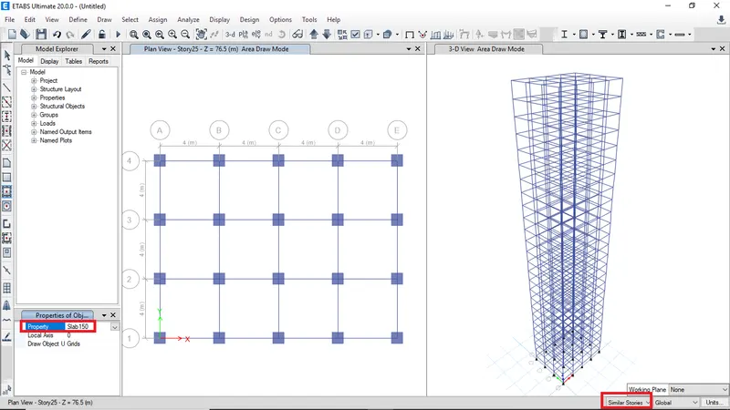
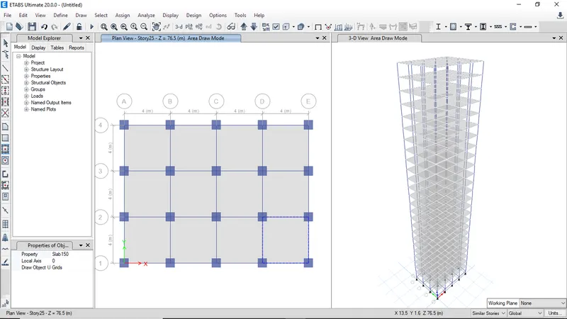
- Plan and 3d view after creating all elements
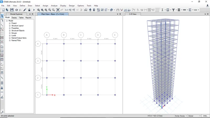
- Swith to base floor plan
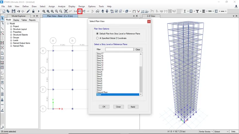
- To assign support select all the columns
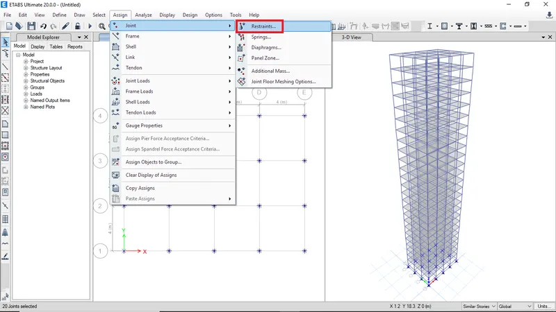
- Goto assign, joint then click restraints to assign support
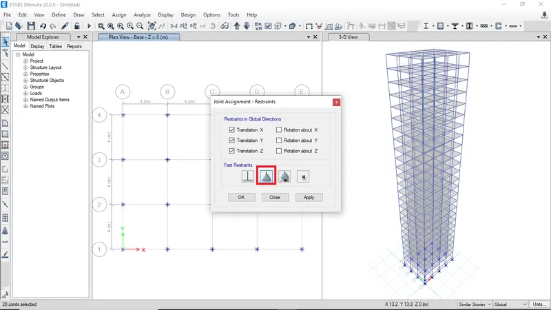
- Select pinned connection then click ok
Defining and assigning load patterns - To define load types goto load patterns in define menu
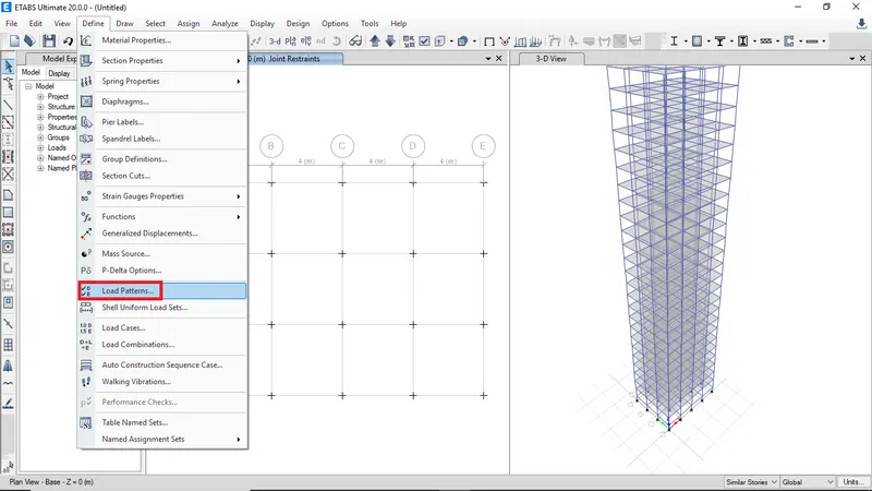
- Type load name and select load type then click add new load to add create new load patterns
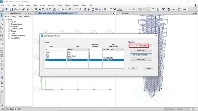
- Select EqX and click on modify lateral load to edit seismic coefficients and seismic data as per data provided in the question
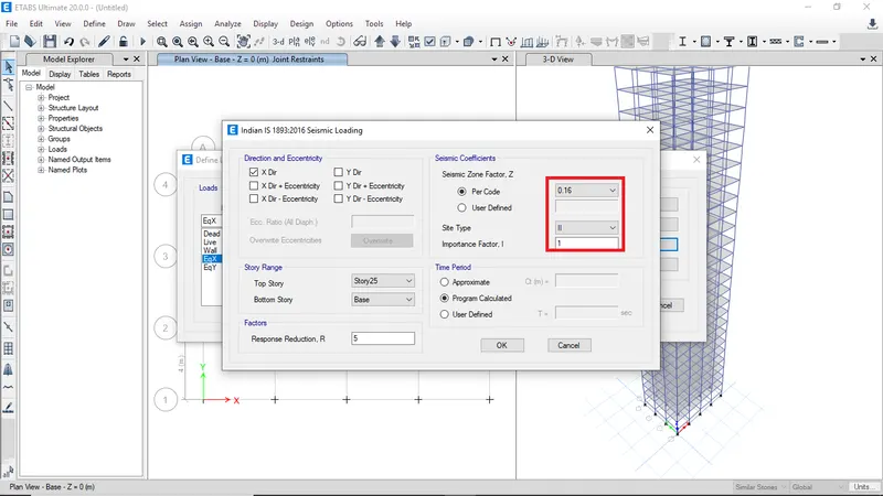
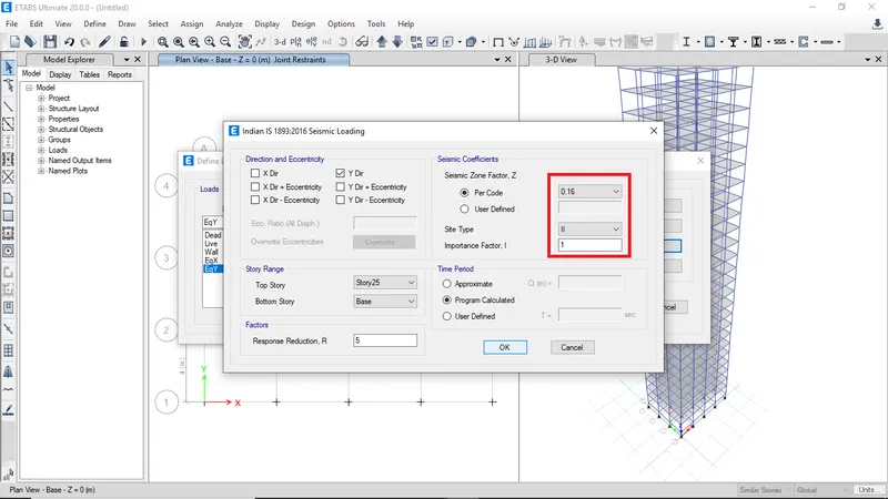
- Similarly modify EqY data abd click ok
- To define load combination click on define yhen click on load combinations
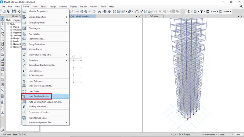
- Click on add default design combos to generate load combinations
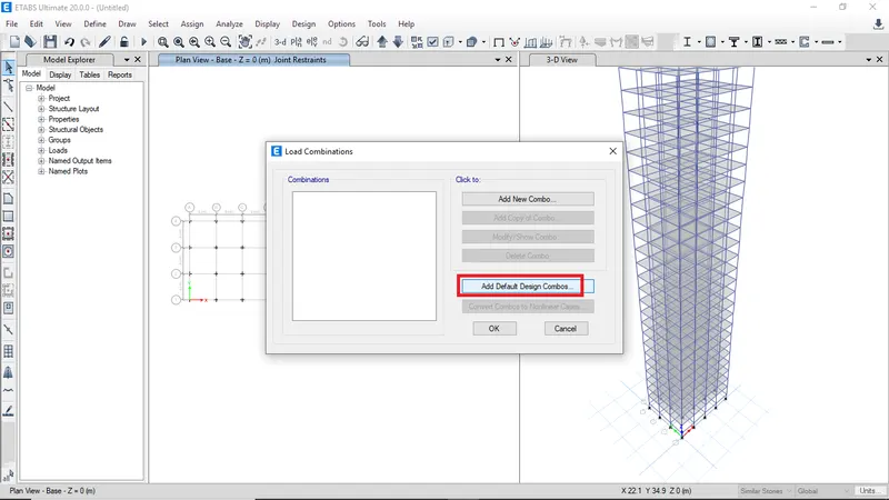
- Select concrete frame design and check convert to user combinations to edit them
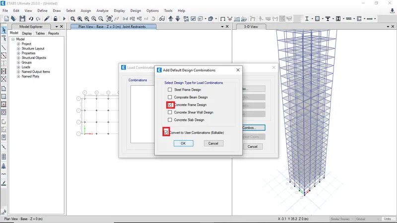
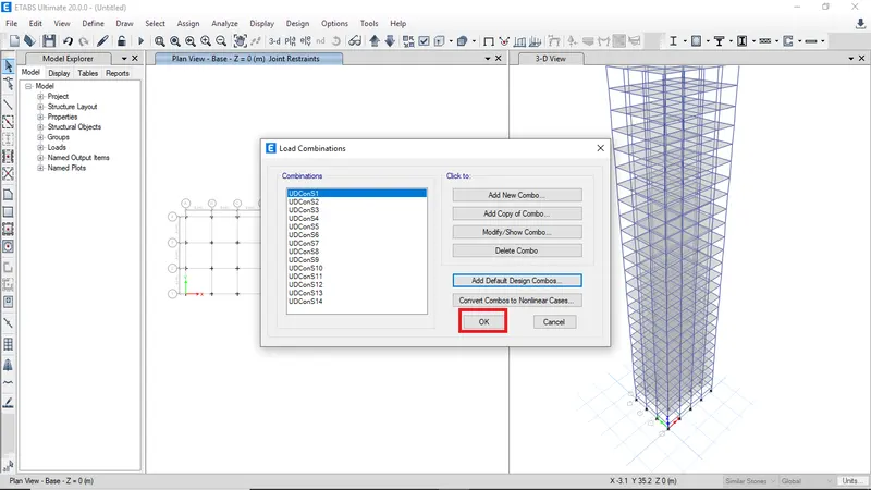
- After generating load combinations click ok
- To assign the defined loads to the members need to select and assign the respective loads
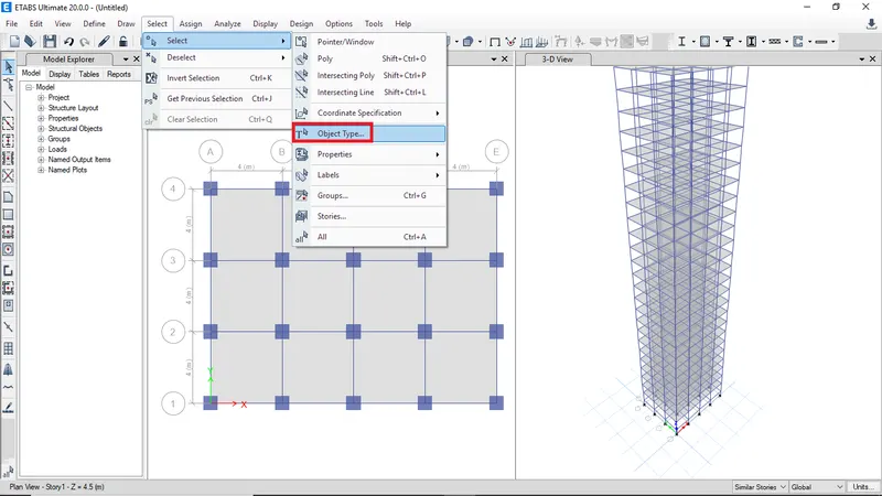
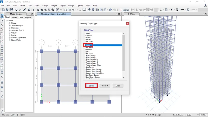
- Click on select then click on object type
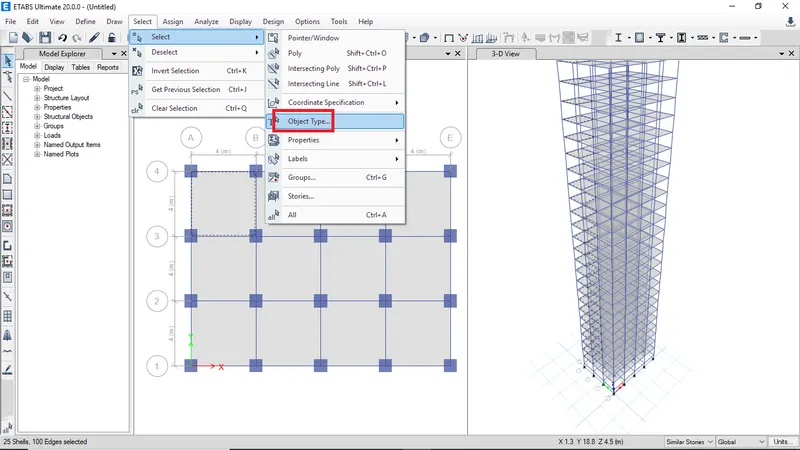
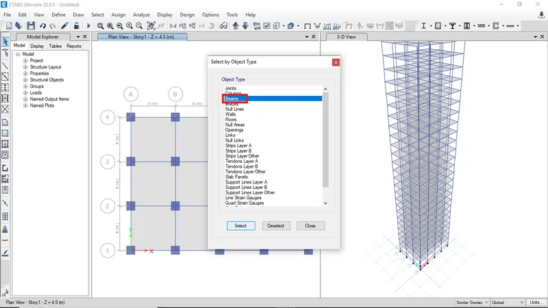
- Click on floors then click on select and then close
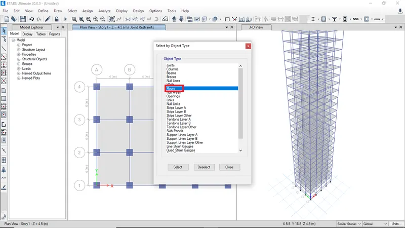
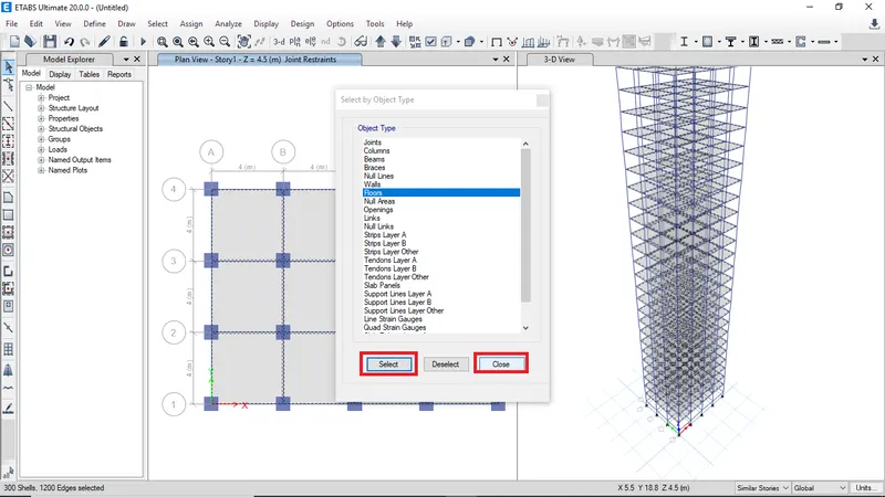
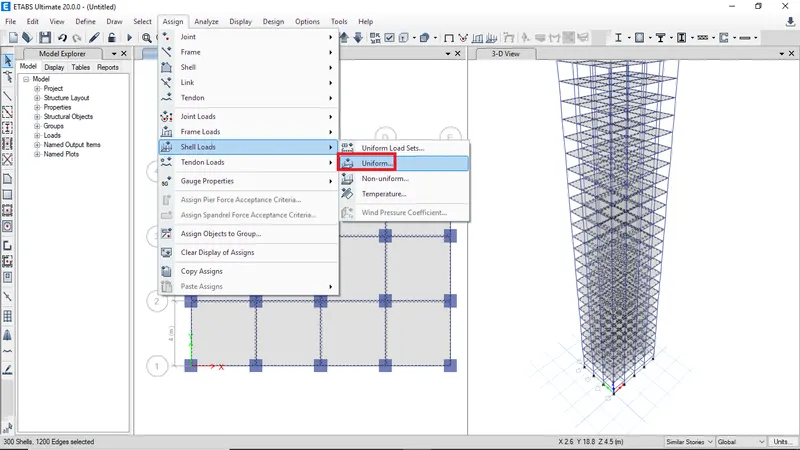
- To addign the live load to slab goto assign then click on shell loads then select uniform load
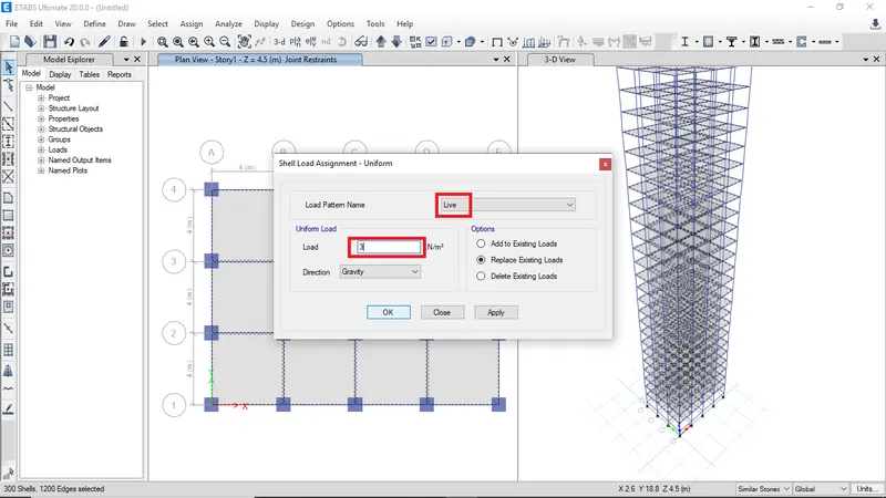
- Select load pattern as live then enter the load value as 3 then click ok
- The assigned floor loads can be seen in the screen
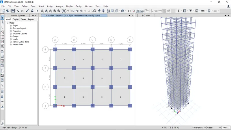
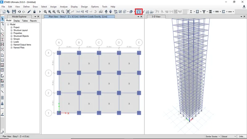
- To toggle the assigned loads on and off click on show undeformed shape.
- To assign the wall loads on beams select the beams by object type
- Click on beams then click select and then click close
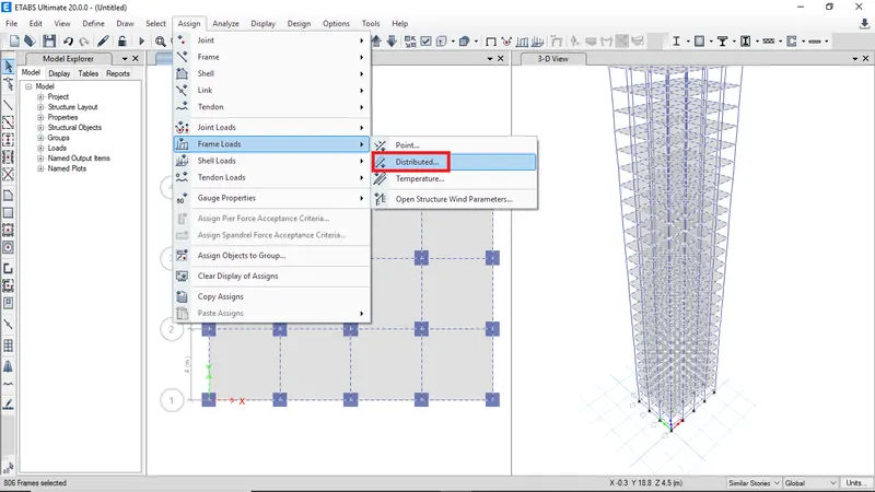
- To assign frame loads goto assign then select frame loads and select distributed load
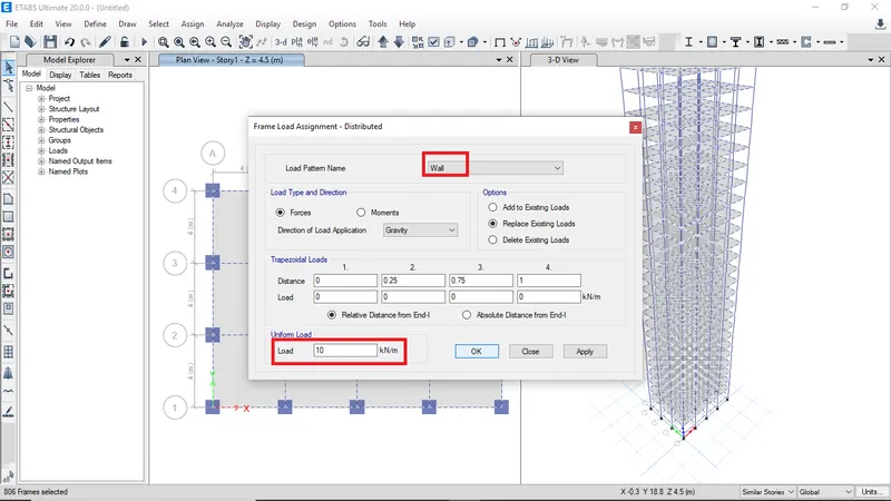
- Chose load parrern as wall then provide load value as 10 kN/m
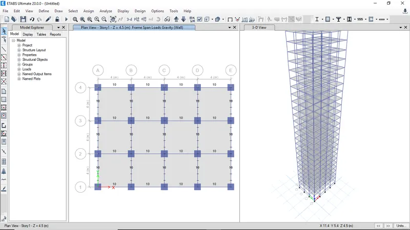
- The assigned frame load can be seen
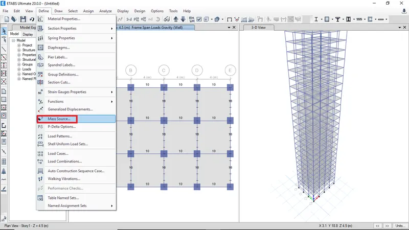
- To create the mass source goto define then click on Mass source
- Select modify mass source
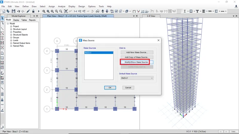
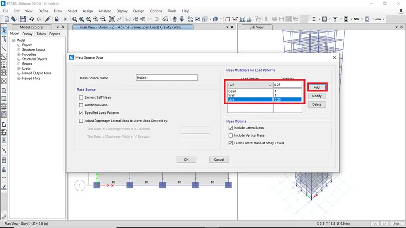
- Then check only specified load patterns and add the loads with multiplier
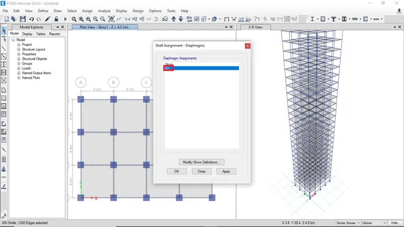
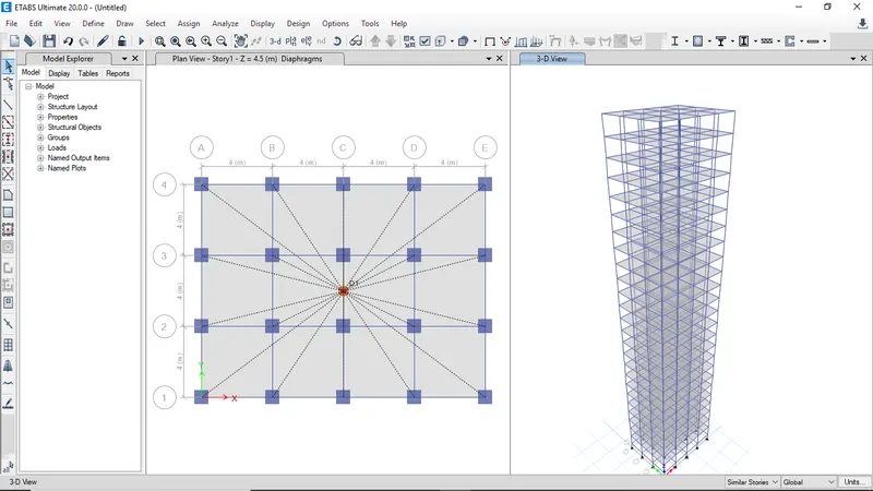
- To assign Diaphragm select all the floors
- Goto shells then select Diaphragms
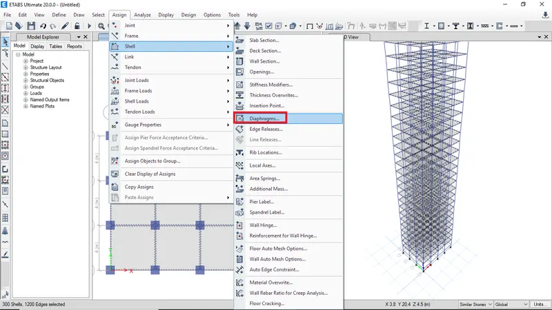
- Select Diaphragm D1 then click ok
- The mass source can be seen
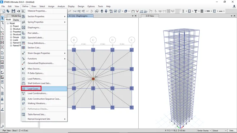
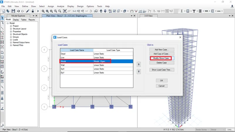
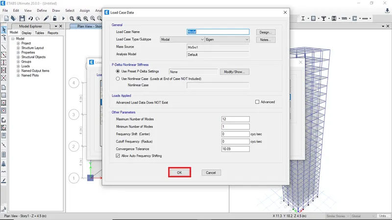
- Click on load cases to modify modal load case
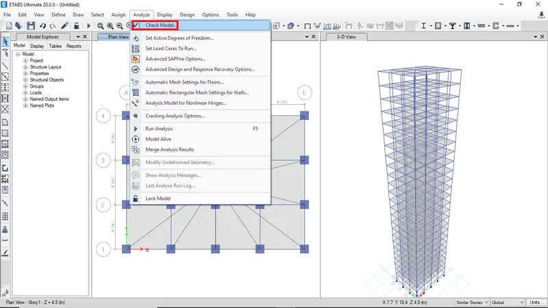
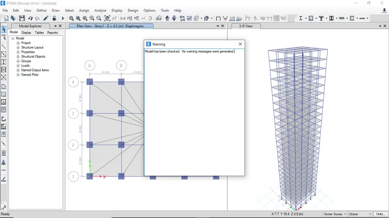
- Goto analyse then click on check model to check for errors
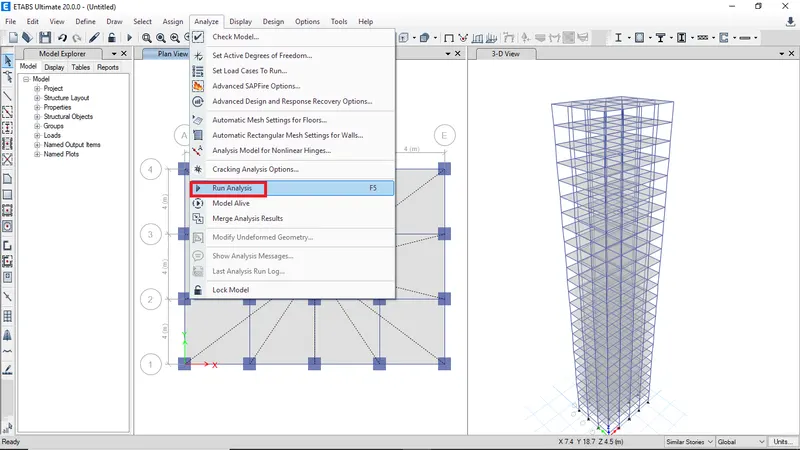
- Then goto analyse and click Run analysis to analyse model
- After complete analysis goto display click on show tables to view result data
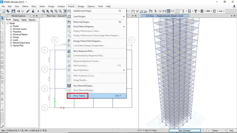
- Select Modal participation mass ratios and click OK
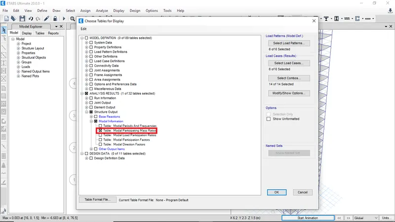
- Modal periods and frequencies
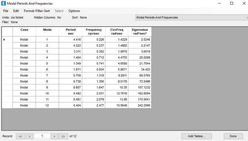
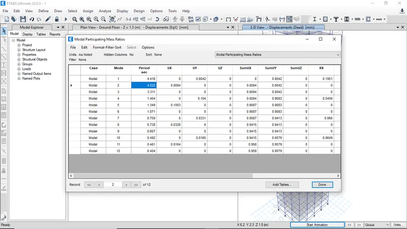
- Modal participation and mass ratio table is as follows.
RESULT
25 storey building is modelled with structural properties and analysed in ETABS - The translational fundamental natural period of vibration in both the X and Y direction is approximately: TX1= 4.416 second TY1= 4.222 second
- From the ETABS analysis results it is clear that the torsional time period is less than two translational time period as in Table 5 of IS 1893 (part 1) – 2016, So torsional irregularity satisfied.
- Vertical irregularity check if the two provisions of clause 7 in Table 6 (shown below) of IS 1893 (part 1) – 2016,
- By adding the first three-mode mass ratios we get 80% which means first three modes of seismic oscillation contribute more than 65% of building weight as per ETABS analysis
- The fundamental lateral natural periods in two principle directions are not away from each other by 10%.
- The storey drift for serviceability Base shear case (EqX or EqY) is shown in below graph
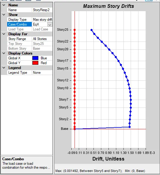
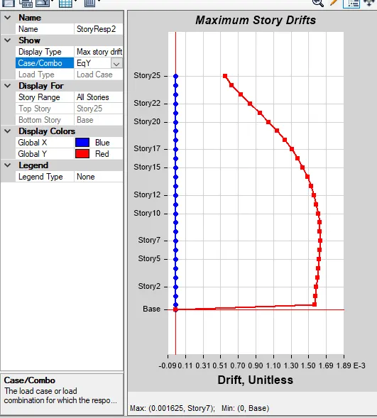
- The storey drift not exceeded 0.004times the storey height for base shear with no load factors is satisfied as provision on inter-storey drift limitations in clause 7.11.1.1 of IS 1893:2016