MBD Simulation on IC Engine Valve Train
MBD SIMULATION ON IC ENGINE VALVE TRAIN
AIM
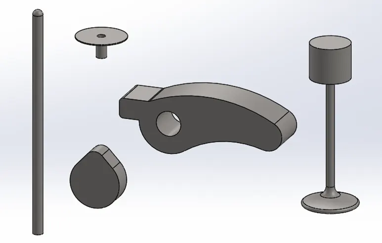
To design the 3D models of cam, pushrod, rocker arm, valve stem and valve, and then assemble them to perform the multi body dynamic (MBD) simulation in solidworks.
INTRODUCTION
A valve train is a mechanical system that controls the operation of the intake and exhaust valves in an internal combustion engine. The intake valves control the flow of air/fuel mixture (or air alone for direct-injected engines) into the combustion chamber, while the exhaust valves control the flow of spent exhaust gasses out of the combustion chamber once combustion is completed. The valvetrain consists of all the components responsible for transferring the rotational movement of the camshaft into the opening and closing of the intake and exhaust valves. Typical components are listed below in order from the cam to the valves.
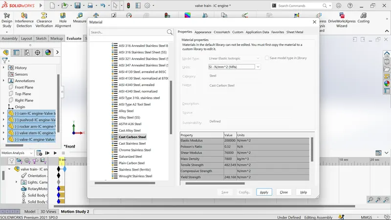
Here starts the design of each part in separate part files and assemble them for start up this simulation. The objective of the project is to calculate the valve lift and contact force between mating parts in two different “cam profile”. Using “cam lift” formula that cam was designed for both processes. Also, the cast carbon steel material is used for all the part models to obtain the real time results.
THEORY
The valvetrain layout is largely dependent on the location of the camshaft. The common valvetrain configurations for piston engines - in order from oldest to newest are:
- Flathead engine: The camshaft and the valves are located in the engine block below the combustion chamber.
- Overhead valve engine: The camshaft remains in the block; however, the valves are located in the cylinder head above the combustion chamber.
- Overhead camshaft engine: The valves and camshaft(s) are in the cylinder head above the combustion chamber.
In recent time the third type is most commonly using one in automobile industries. But this project taken from second type. So, lets start the parts details and design calculations.
Camshaft: The timing and lift profile of the valve opening events are controlled by the camshaft, through use of a carefully shaped lobe on a rotating shaft. The camshaft is driven by the crankshaft and in the case of a four-stroke engine rotates at half the speed of the crankshaft. Motion is transferred from the crankshaft to the camshaft most commonly by a rubber timing belt, a metallic timing chain or a set of gears.
Pushrod: Pushrods are long, slender metal rods that are used in overhead valve engines to transfer motion from the camshaft (located in the engine block) to the valves (located in the cylinder head). The bottom end of a pushrod is fitted with a lifter, upon which the camshaft makes contact. The camshaft lobe moves the lifter upwards, which moves the pushrod. The top end of the pushrod pushes on the rocker arm, which opens the valve.
Rocker arm: Depending on the design used, the valves are actuated by a rocker arm, finger or bucket tappet. Overhead valve engines use rocker arms, which are actuated from below indirectly (through the pushrods) by the cam lobes. Overhead camshaft engines use fingers or bucket tappets, which are actuated from above directly by the cam lobes.
Valves: Most modern engines use poppet valves, although sleeve valves, slide valves and rotary valves have also been used at times. Poppet valves are typically opened by the camshaft lobe or rocker arm, and closed by a coiled spring called a valve spring. Valve float occurs when the valve spring is unable to control the inertia of the valvetrain at high engine speeds (RPM).
Cam Lift: Now let’s start how to calculate the cam profile dimensions using cam lift formula. In cam design there are two circles which dimensions are given and same for both profiles. But the center distance is different which help to achieve the different valve lift.
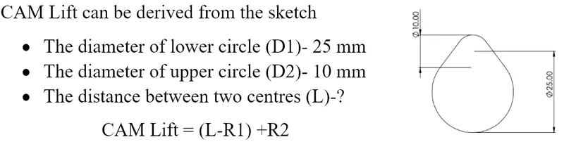
In this project the two different cam lift values are given. So, using the above formula we need to find out the center distance.
STUDY SETUP
The entire study setup for this project is followed in the following manner. It will help us to understand about this project step by step easy and convenient. First the all-part designs are completed one by one separately and assembled it.
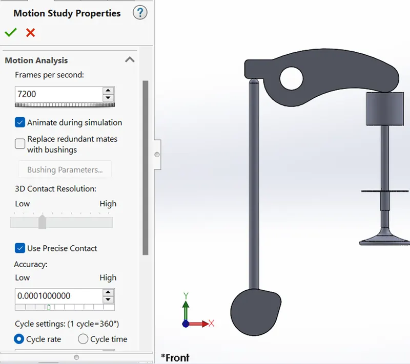
After assemble let stared MBD simulation by following setups. First the motion study properties which help for obtain the proper and accurate output plots. Here I assigned 7200FRS and used precise contact option also.
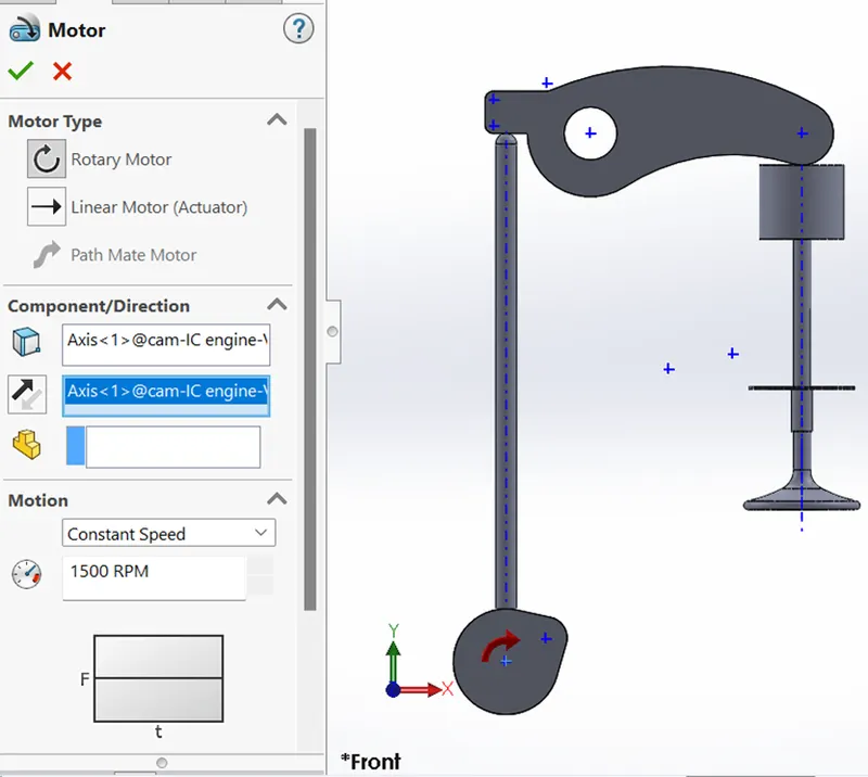
The CAM is assumed as motor which translates rotational motion into linear motion and it rotates at constant speed of 1500rpm.
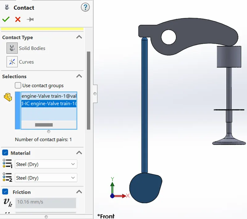
Contact is most important in motion study where the number of parts are assembled. But without contact each parts moves randomly. Here there are three contacts given that enough for proper motion of assembled body.
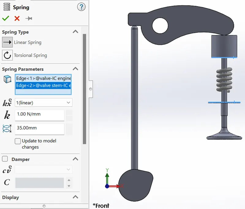
Spring is setup between valve and valve stem for restore the valve. That means it help in valve opening and closing that is valve lift. In this setup we need to know about spring constant which give smooth motion of parts. For my aspect 15N/mm and free length 55mm is fine to achieve this.
Material for all the parts is assumed as cast carbon steel for match the real time application. Without material the output result slightly differs from what we expected.
RESULT
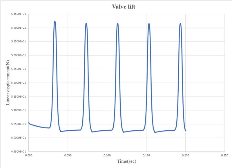
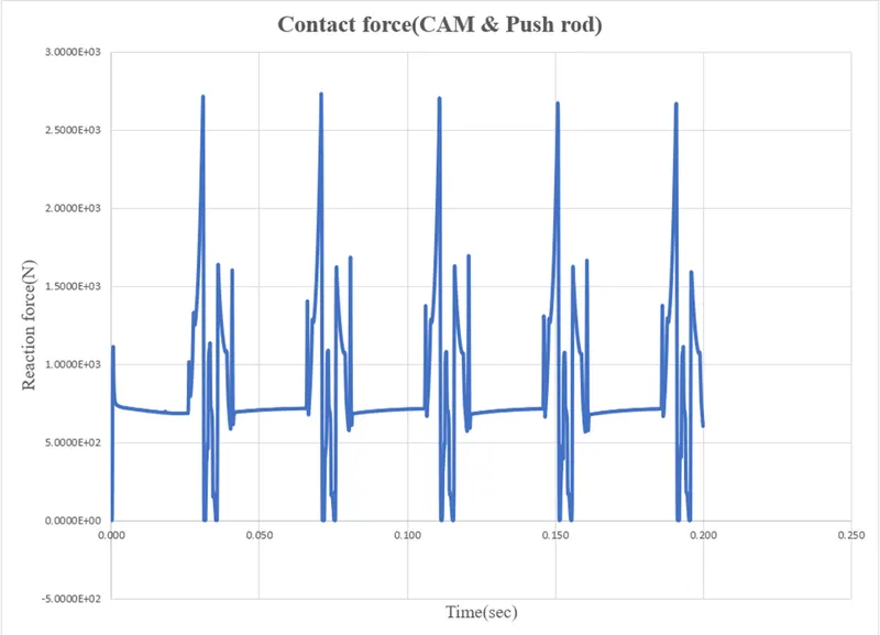
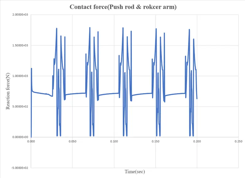
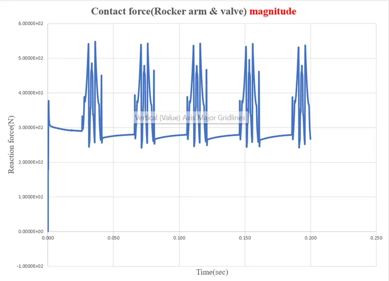
After the all above setups are completed, we can move on into the motion study analysis of IC engine valve train with following two conditions.
Case(i): CAM lift = 3.5mm
CAM lift = 3.5 = (L-12.5) + 5
Center distance(L) = 11mm
https://www.youtube.com/watch?v=6Vn4kVkBlxg
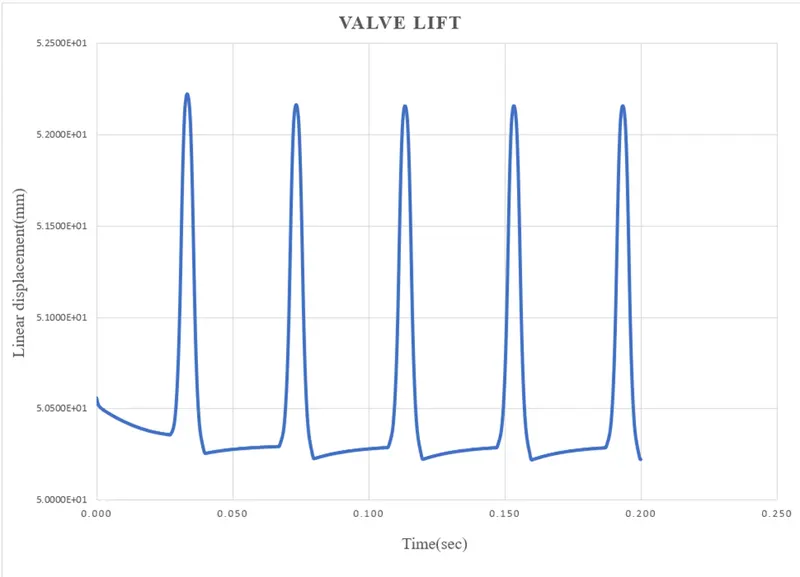
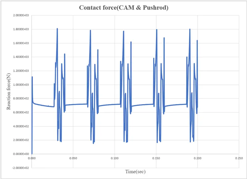
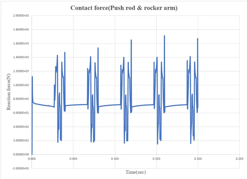
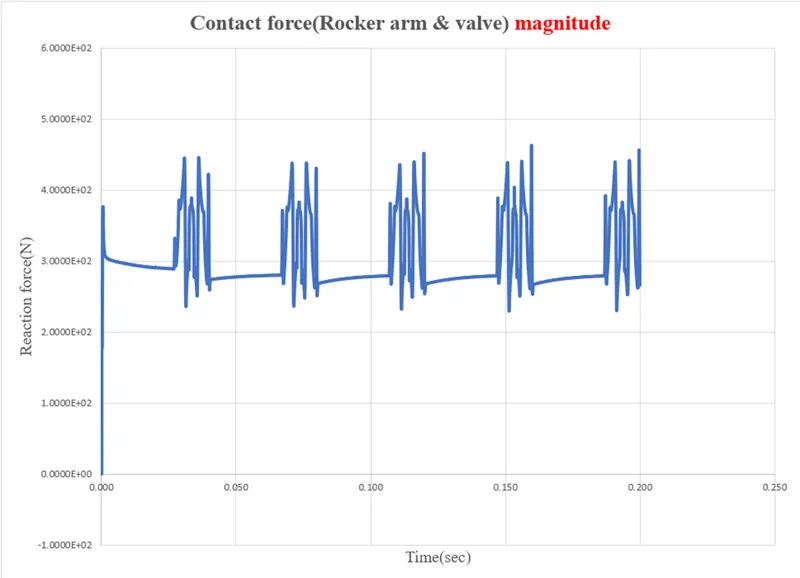
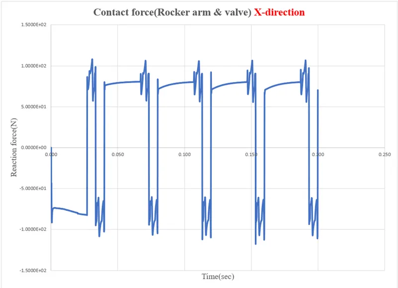
Case(i): CAM lift = 3.5mm
CAM lift = 6 = (L-12.5) + 5
Center distance(L) = 13.5mm
https://www.youtube.com/watch?v=rPQ2cVvRHsk
CONCLUSION
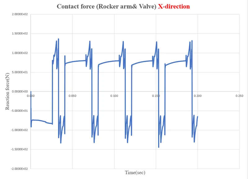
The magnitude represents net contact force between the parts, while the contact force along x direction is the frictional force between the bodies that arise duo to the rocker arm sliding over the surface of the valve head.
The change in direction of the force is because the rocker arm first slides towards origin giving a positive friction force and then slides away from the origin giving rise to friction in the negative x-direction. Therefore, the plots are opposite to each other.
The result is same for the CAM lift 6mm, only it differs in magnitude of contact force. The movement in this case is quite smoother compared to the CAM lift 3.5mm as observed. As the CAM lift increases more air-fuel mixture can enter into the cylinder of IC engine.