MBD Simulation on a Piston Assembly
MBD of Piston Assembly
Aim:
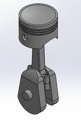
To create all the parts of piston assembly and assemble them in assembly workbench and run the motion analysis using SolidWorks motion study.
Objective:
- To create all parts of piston assembly and assemble.
- To run motion study analysis for the following cases.
- To plot the linear displacement of the piston head in all three cases and then superimposing graphs by exporting them to Microsoft excel.
| Sl.No | Wrist Pin Offset ` | Crank Speed (Rpm) |
| 1 | "0" mm | 2000 |
| 2 | 10 mm Positive | 2000 |
| 3 | 10 mm Negative | 2000 |
Theory:
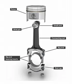
- A piston is a component of reciprocating & engines, reciprocating pumps, gas compressors, hydraulic & pneumatic cylinders among other similar mechanism.
- It is a moving component that is contained by a cylinder and is made gas tight by piston rings.
- In an engine, its purpose is to transfer force from expanding gas in the cylinder to the crankshaft via the piston rod or connecting rod.
- In some engines, the piston act as a valve by covering and uncovering ports in the cylinder.
- Various application is used piston assembly such as hydraulic cylinder.
- Various application is used piston assembly such as hydraulic cylinder, shock absorber, fire piston & syringe.
Procedure:
Create all parts:
Crank:
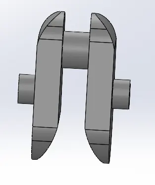
- A crank is an arm attached at a right angle to a rotating shaft by which circular motion is imparted from the shaft.
- In a reciprocating engine, it translates reciprocating motion into rotational motion.
- Crank is a rotating part of the piston assembly.
Piston head:
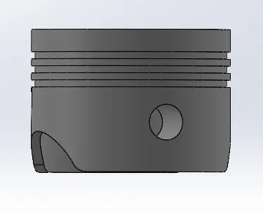
- The piston is a moving disk enclosed in a cylinder that is made gas-tight by piston rings.
- A piston aids in the transformation of heat energy into mechanical work and vice versa.
- Piston is a key component of heat engines.
- Piston is worked by transforming force output by expanding gas cylinder to a crankshaft which provides rotational momentum to flywheel such system is known as "reciprocating engine".
Connecting rod & End cap:
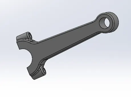
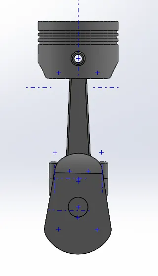
- A connecting rod is the part of a piston that end connects the piston to the crankshaft together with the crank.
- The connecting rod convert the reciprocating motion of the piston into the crankshaft.
- The connecting rod is required to transmit the compressive and tensile force from the piston.
- In an internal combustion engine. It allows pivoting on the piston end and rotation on the shaft end.
- Its most common usage allows internal combustion engine and steam engine.
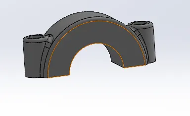
- An end cap is the removable section of a two-piece connecting rod that provides a bearing surface for a crankpin journal.
Gudgeon Pin (Wrist Pin):
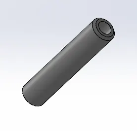
- In an IC engine, the gudgeon pin connects the piston to the connecting rod.
- Provides bearing for the connecting rod to pivot upon as the piston moves.
Assemble All Parts:
Motion Study Analysis:
The motion study: In the motion study the following steps are performed.
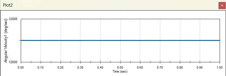
- Motor is given to crank with the speed 2000rpm in clockwise direction.
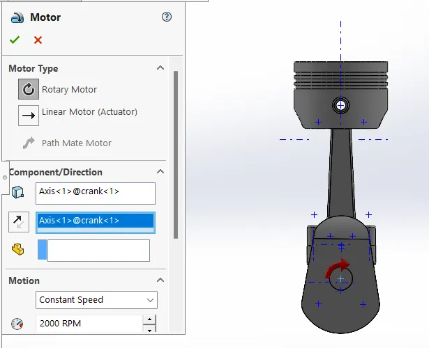
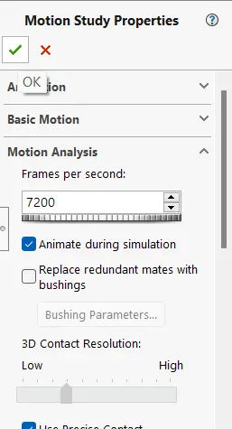
- Frames per second are given as 7200 with precise contact.
- Contact is given between all parts.
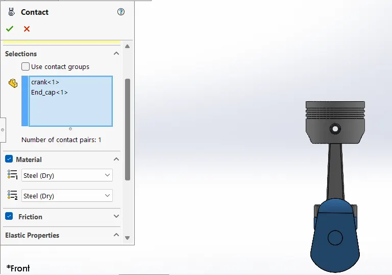
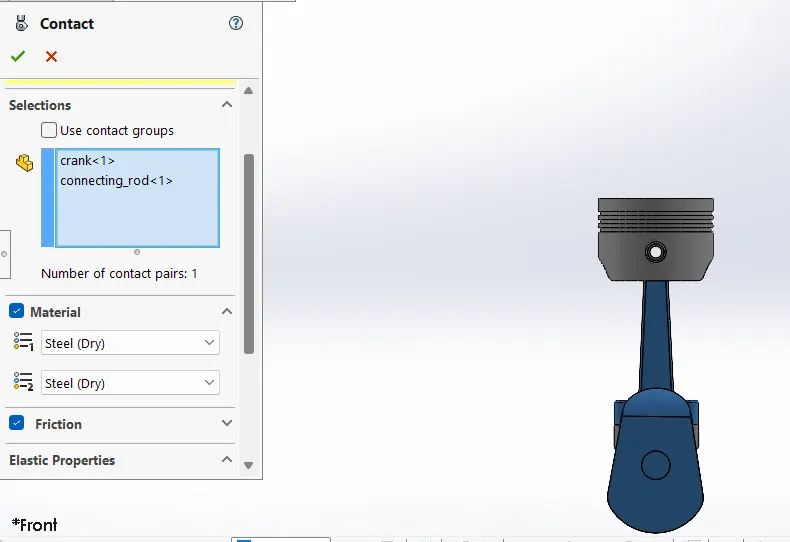
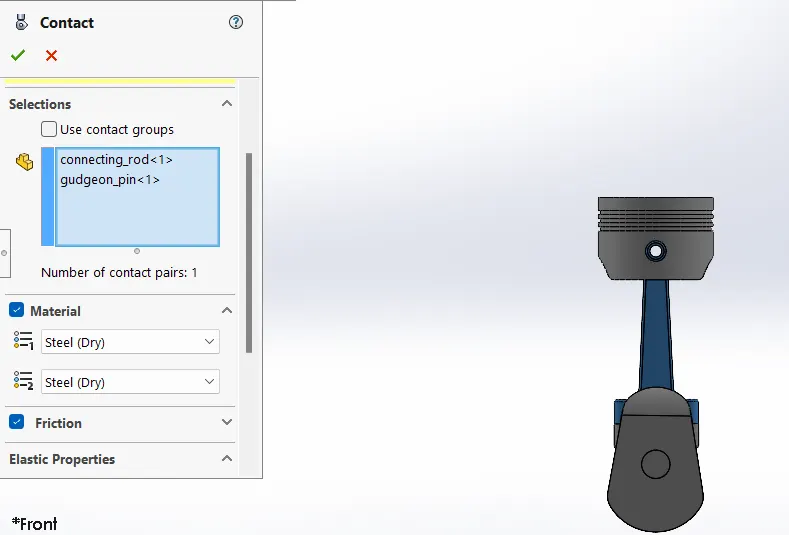
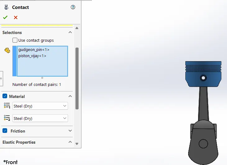
- The material selected for each case is steel (Dry).
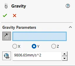
- Gravity in the Y direction (Downward).
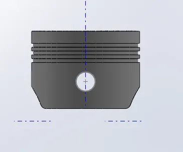
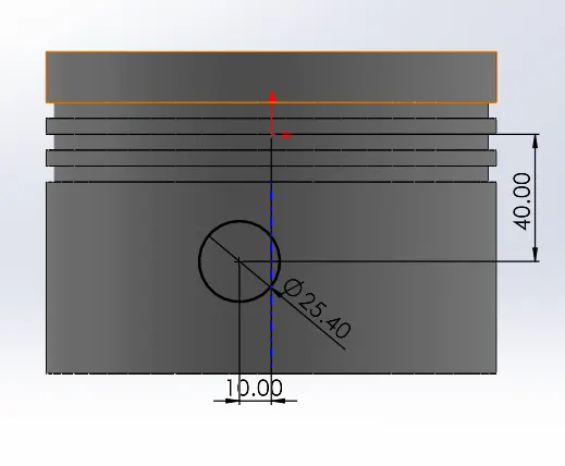
| Sl.No | Wrist Pin Offset ` | Crank Speed (Rpm) |
| 1 | "0" mm | 2000 |
| 2 | 10 mm Positive | 2000 |
| 3 | 10 mm Negative | 2000 |
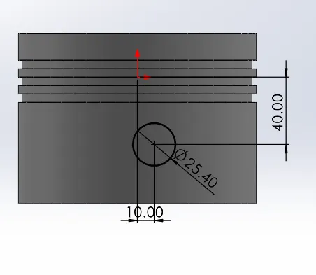
Case 1: Linear Displacement at "0 mm" Offset
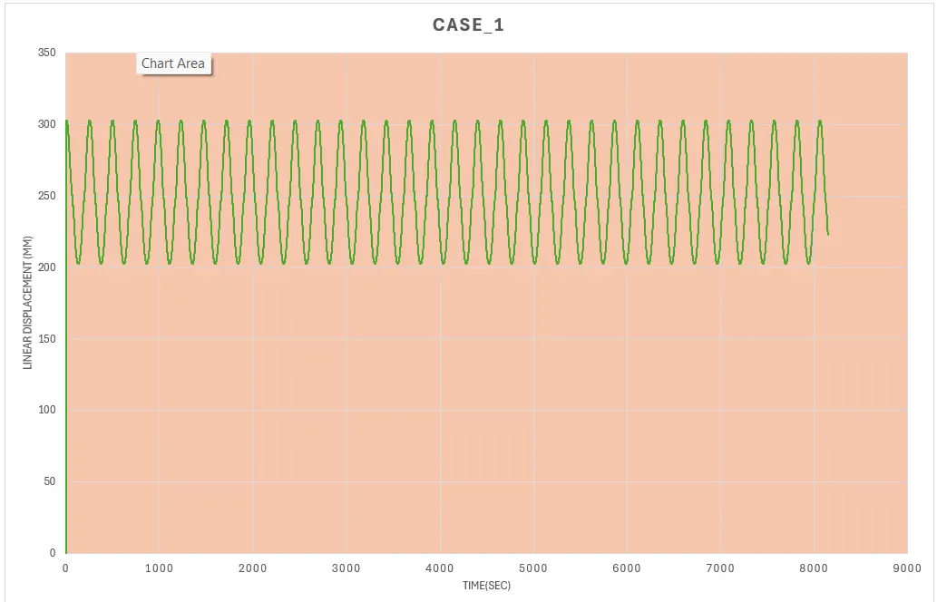
- In this plot x axis is Time in seconds and y axis is Linear displacement of the piston head which is move from TDC to BDC.
- In this plot BDC at around 132mm to TDC 230mm.
- So, the range is 98mm. So, the piston is move 98mm linearly.
- This happens in the regularly and create same wave patterns.
Case 2: Linear Displacement at "10 mm" Positive Offset
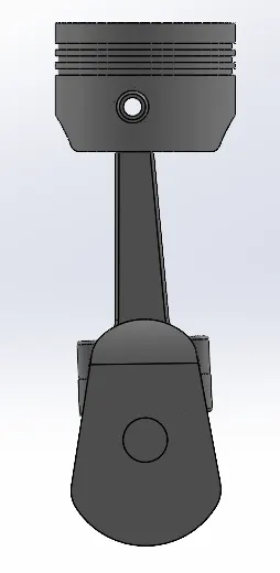
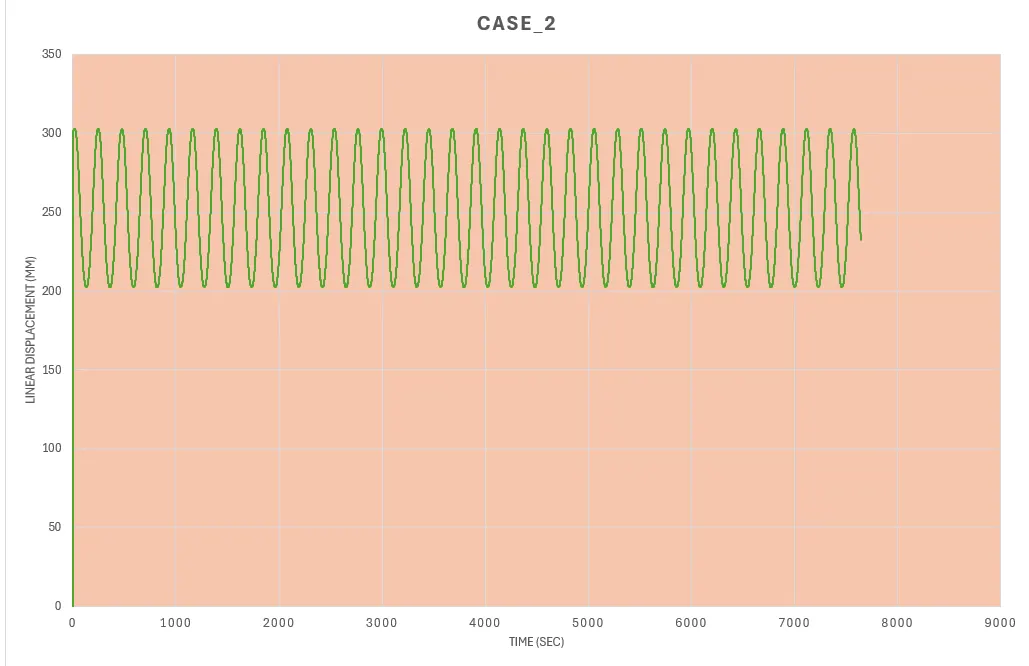
- In this plot x axis is Time in seconds and y axis is Linear displacement of the piston head which is move from TDC to BDC.
- In this plot BDC at around 132mm to TDC 230mm.
- So, the range is 98mm. So, the piston is move 98mm linearly. This happens in the regularly and create same wave patterns.
Case 3: Linear Displacement at "10 mm" Negative Offset
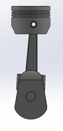
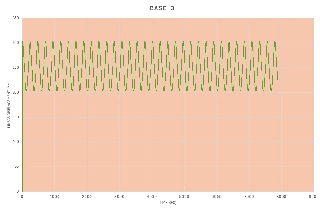
- In this plot x axis is Time in seconds and y axis is Linear displacement of the piston head which is move from TDC to BDC.
- In this plot BDC at around 132mm to TDC 230mm.
- So, the range is 98mm. So, the piston is move 98mm linearly.
- This happens in the regularly and create same wave patterns.
ASSEMBLY FLIE OF PISTON
https://drive.google.com/drive/folders/1UTITc0xcfIt4jtlfitKIviTRgB4XtJTU?usp=sharing