Week 4-1D Element Creation Challenge
Aim:
To mesh the given component with the size of 5 units and create 1D elements on the following component with given cross-section and DOF>
Given data:
a. Rod element:- Translational DOF should be Constrained with RBE2 link
Cross-Section: BOX- Dimension a= 12 mm
dimension b=10 mm
Thickness t= 0.75 mm
b. Beam element:- All DOF should be constrained with RBE3 link
Cross-Section: I Section- Dimension a= 8 mm
Dimension b= 10 mm
Dimension c= 8.5 mm
Thickness t1= 0.75 mm
Thickness t2= .6 mm
Thickness t3= .6 mm
c. Bar element:- Constrain only x and y DOFs With RBE3 link
Cross-section: X section- Dimension DIM1= 5 mm
Thickness DIM2= 1.2 mm
Dimension DIM3= 10 mm
Thickness DIM4= 1.2mm
d. & e. Apply the mass of magnitude 10 with the RBE2 link
f. Join the two components with Spring elements
Theory:
Project methodology:
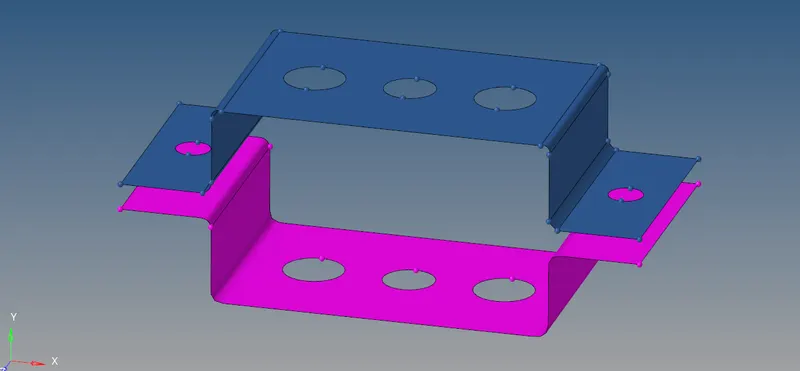
1.Mid surface:
- Auto mid surface has been used to extract the midsurface for this siple bracket.
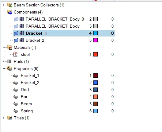
- Components has been created and assigned to the particular mid surfaces.
2.Assign material:
- Create material.
- Here i have created a material and assigned to steel.
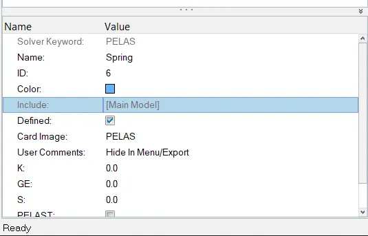
3.Assign property:
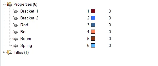
- Create property.
- Enter thickness value and element type.
- Also assign this created property to the particular component and material.
4.Washer split:
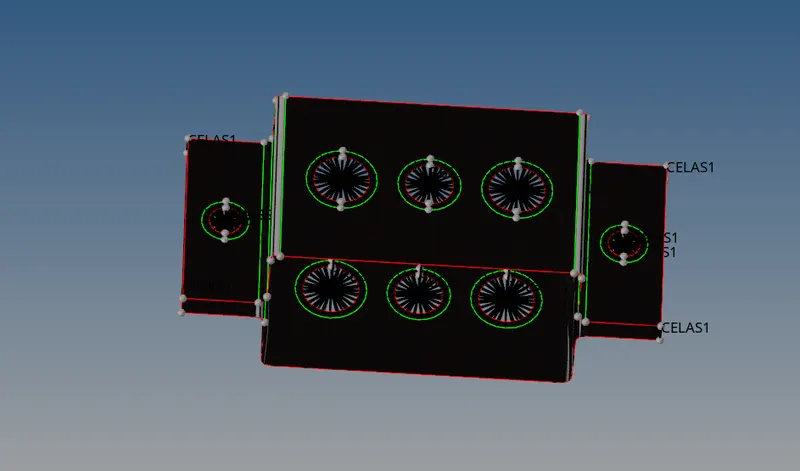
- Washer split is used to capture the mesh near the holes properly.
- The washer split offset value is given to 5 units in this project.
5.2D mesh:
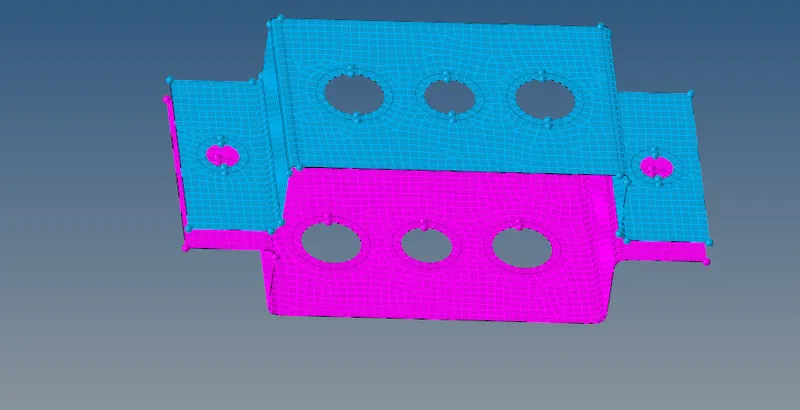
- For this project auto mesh is been performed for the element target length of 5 units.
6.1D element:
- Same 1D elements used in this project are,
- PBAR
- PROD
- PBEAM
- RBE2
- RBE3.
- As per the given details i have deployed the 1D elements.
- To deploy bar,rod,beam elements HYPERBEAM has been used.
- Where HYPERBEAM IS USED TO CRATE A CROSS SECTION.
7.Hyperbeam:
For the given data a.rod element,b.Beam element,c.Bar element we will be creating a cross section using hyper beam.
a.Rod element-(cross section-Box):
Translational DOF should be constrained with RBE2 link.
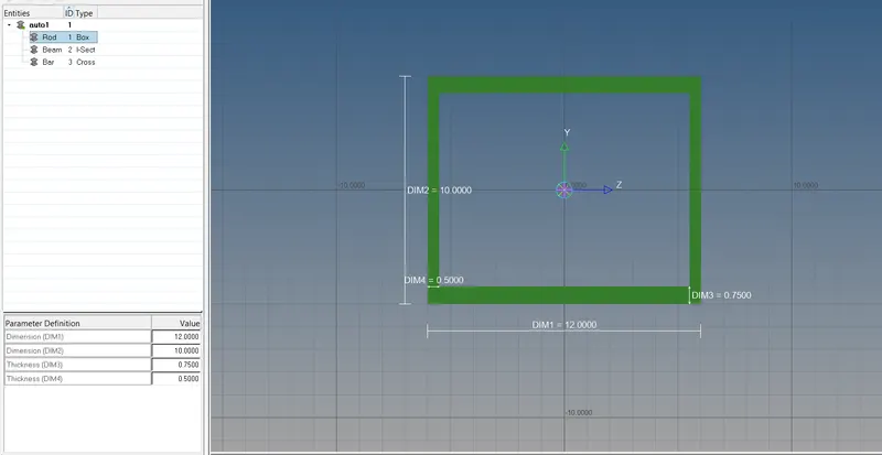
- The given cross section details for rod element are,
-
Dimension a= 12
-
dimension b=10mm
-
Thickness t= 0.75 mm
- To create this cross section go to-1D -hyperbeam-create-standard section-hypermesh-thin walled box.
- The standard cross section shape will be created and enter the given dimension data .
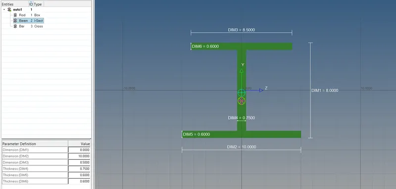
b.Beam element:
All DOF should be constrained with RBE3 link.
- Cross section : I Section-
- Dimension a= 8 mm
- Dimension b= 10 mm
- Dimension c= 8.5 mm
- Thickness t1= 0.75 mm
- Thickness t2= .6 mm
- Thickness t3= .6 mm.
- To create this cross section go to-1D -hyperbeam-create-standardsection-hypermesh-I-section.
- The standard cross section shape will be created and enter the given dimension data.
c.Bar element:
Constrain only x and y DOFs With RBE3 link.
- The given cross section details for bar elements are,
Cross-section: X section-
- Dimension DIM1= 5 mm
- Thickness DIM2= 1.2 mm
- Dimension DIM3= 10 mm
- Thickness DIM4= 1.2mm
- To create this cross section go to-1D-hyperbeam-create-standard section-optistruct-cross.
- The standard cross section shape will be created and enter the given dimension data.
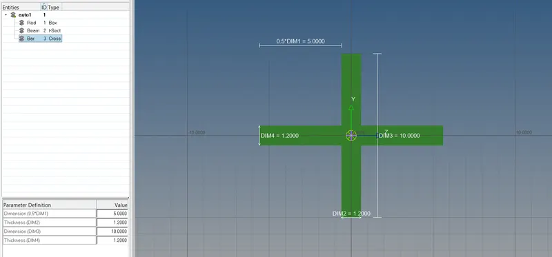
Hence ,the cross section has been created for bar,rod,beam element as per given data.Now these cross section should be assigned to the particular property.
8.Approach:
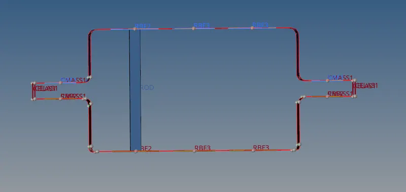
a.Approach for Rod element:
- Created RBE2 link element for hole (a) by constraing translational as per input data.
- Created CROD element by connecting hole(a).
- CROD-Thin walled cross section as per input.
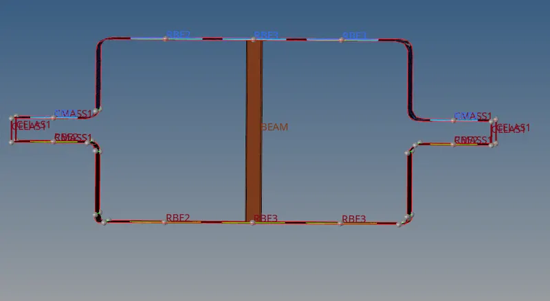
b.Apprach for beam element:
- Created RBE3 cluster element for hole (b) by constraing all DOF asd per input data.
- Created CBEAM element by connecting hole(B).
- CBEAM -I-cross section as per input.
c.Approach for Bar element:
- Created RBE3 cluster element for hole (C) by constraing only X and Y DOF as per the input data.
- Created CBAR element by connecting hole(c).
- CBAR-X- section as per input.
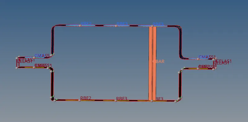
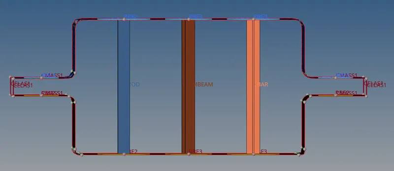
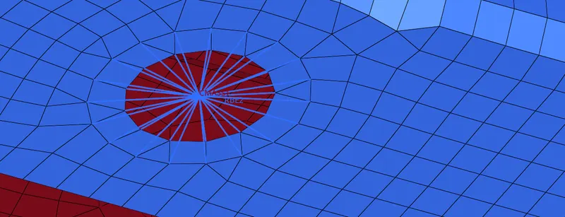
d&e.Apply the mass of magnitude 10 with the RBE2 link:
- Created RBE2 cluster element for hole (d & e) as per input data.
- Applied a mass of magnitude 10.
- CMASS.
f.Join the two components with spring elements:
- Spring elements are created at the four corners of the brackets to join the component.
- CELAS.
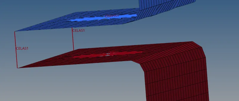
Approach f
Finally, select 1D detailed element representation to view the cross section of bar,beam,bar element and select 2D detailed element reresentation to view the thickness of the mid surface .
Conclusion:
The mesh and creation of 1D element has been successfully achived as per the given inputs.