MBD Simulation on a Piston Assembly
MOTION ANALYSIS ON A PISTON ASSEMBLY USING SOLIDWORKS
AIM
To design the 3D model of piston, crank shaft, connecting rod and wrist pin with the help of proper drafting for each model. After that all part models are need to assemble and perform the motion analysis in three different wrist pin offset conditions.
INTRODUCTION
A four-stroke (also four-cycle) engine is an internal combustion (IC) engine in which the piston completes four separate strokes while turning the crankshaft. A stroke refers to the full travel of the piston along the cylinder, in either direction. These four strokes can also be referred to as "suck, squeeze, bang, blow" respectively, which can be easier to remember. Four-stroke engines are the most common internal combustion engine design for motorized land transport, being used in automobiles, trucks, diesel trains, light aircraft and motorcycles.
Here we can start the design of four major components for piston assembly such as crank shaft, piston, connecting rod and wrist pin. All parts are designed in separate part file and then assemble it in assembly file. There are three conditions we need to achieve in this project. So, the only different in part design is wrist pin positioning hole in piston head is called wrist pin offset.
THEORY
The slider-crank mechanism is a particular four-bar linkage configuration that converts linear motion to rotational, or vice versa. Internal combustion engines are a common example of this mechanism, where combustion in a cylinder creates pressure which drives a piston. A slider-crank linkage is a four-link mechanism with three revolute joints and one prismatic, or sliding, joint. The rotation of the crank drives the linear movement the slider, or the expansion of gases against a sliding piston in a cylinder can drive the rotation of the crank.
There are two types of slider-cranks:
- In-line: An in-line slider-crank has its slider positioned so the line of travel of the hinged joint of the slider passes through the base joint of the crank. This creates a symmetric slider movement back and forth as the crank rotates.
- Offset: If the line of travel of the hinged joint of the slider does not pass through the base pivot of the crank, the slider movement is not symmetric. It moves faster in one direction than the other. This is called a quick-return mechanism.
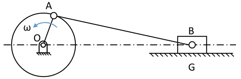
Piston assembly is one of the most important things in automobile, aircraft, marine industries etc. there are many functions achieved by piston assembly. But here we are going to obtain the linear displacement of piston head with three different conditions.

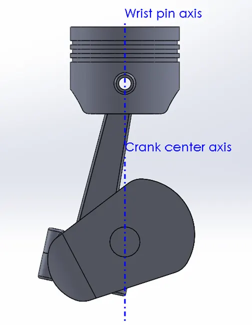
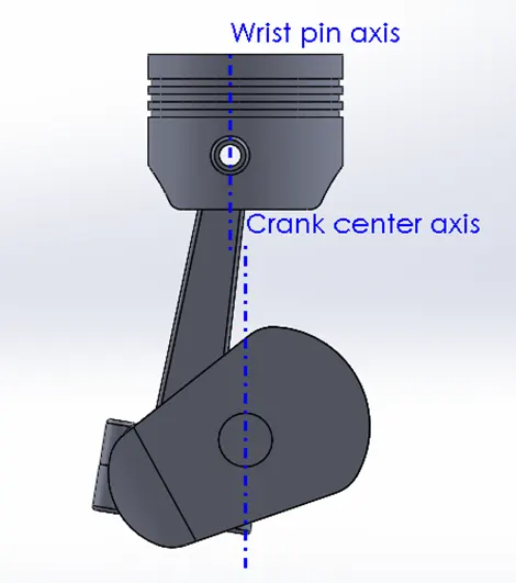
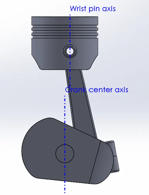
Wrist Pin Offset - The position of the wrist pin is going to be varied as followed. But the center of the axis of the piston head and the crank are coincident to each other (i.e.) They are on the same plane in all the three cases.
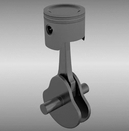
SETUP
The entire study setup for this project is followed in the following manner. It will help us to understand about this project step by step easy and convenient.
(i)piston: A piston is a component of reciprocating engines, reciprocating pumps, gas compressors, hydraulic cylinders and pneumatic cylinders, among other similar mechanisms. It is the moving component that is contained by a cylinder and is made gas-tight by piston rings.
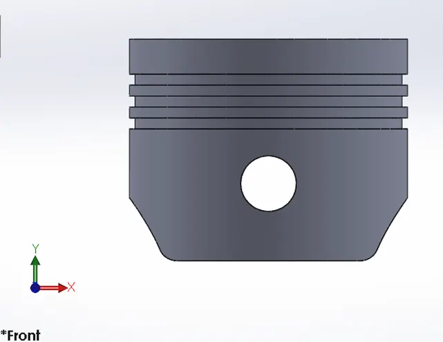
(ii)wrist pin: A gudgeon pin is also commonly known as a wrist pin which is one of the most important components in an internal combustion engine. In IC engines, the gudgeon pin connects the piston to the connecting rod, and provides a bearing for the connecting rod to pivot upon as the piston moves.
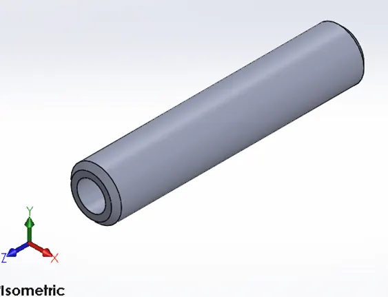
(iii)connecting rod: A connecting rod is the part of a piston engine which connects the piston to the crankshaft. Together with the crank, the connecting rod converts the reciprocating motion of the piston into the rotation of the crankshaft. The connecting rod is required to transmit the compressive and tensile forces from the piston.
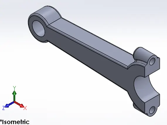
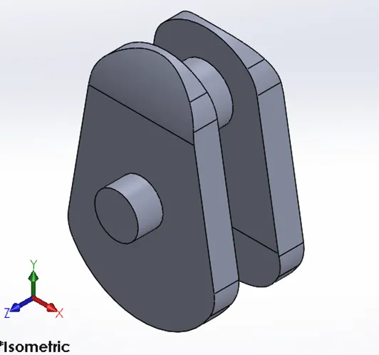
(iv)crank shaft: The crankshaft is essentially the backbone of the internal combustion engine. The crankshaft is responsible for the proper operation of the engine and converting a linear motion to a rotational motion.
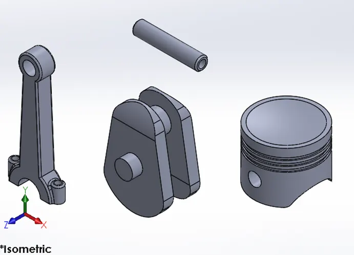
(v)assembly: in assembly file insert all four-part files that mentioned above and using proper mates assemble them together.
(vi)property: motion study properties help us to improve the result quality by increasing the FPS and use precise contact.
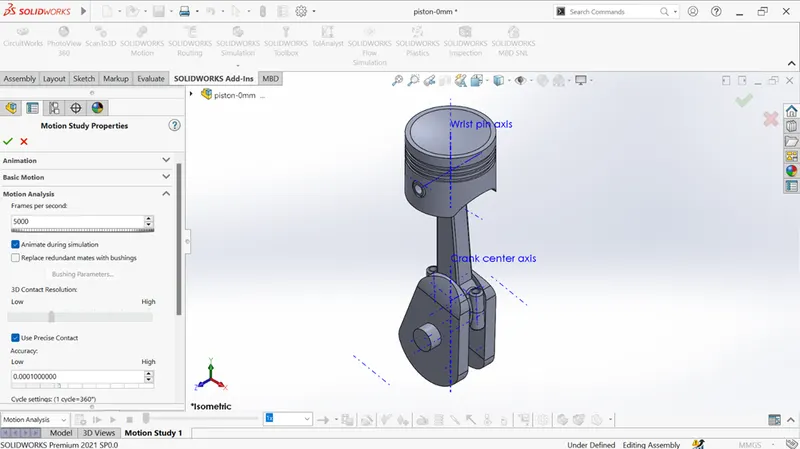
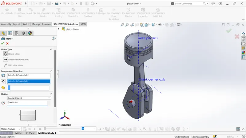
(vii)motor: the center axis of output shaft of the crank shaft is set as motor with constant speed of 2000rpm.
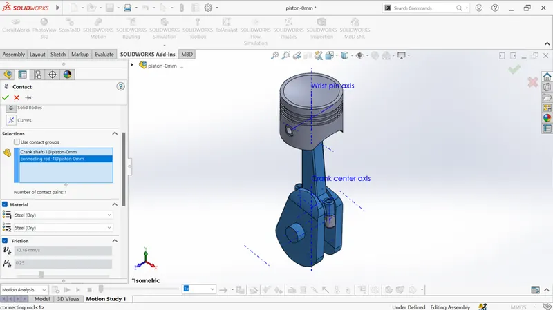
(viii)contact: here we need to give four contacts among four parts. It helps for connecting the parts each other and make the movement of components perfectly.
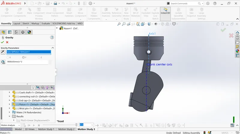
(ix)gravity: the piston center axis is given as gravity parameters which moves downward direction without external force.
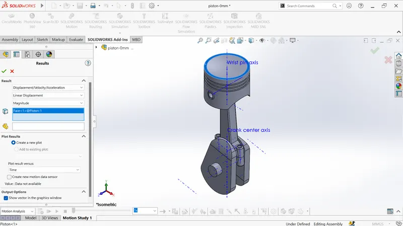
(x)result: liner displacement of the piston we need to calculate with respect to time. So, the upper face of the piston head is selected to achieve this.
After the all above setups are completed, we can move on into motion study analysis of piston assembly with following three conditions.
Case(i): “0” mm offset: - the cut-extrude for wrist pin on piston head is located in center position that is coincident with crank.
https://www.youtube.com/watch?v=sNApnQtbQwA
Case(ii): 10mm positive offset: - the cut-extrude for wrist pin on piston head is located in 10 mm away left side from center position.
https://www.youtube.com/watch?v=N0_sdNuR8cE
Case(iii): 10mm negative offset: - the cut-extrude for wrist pin on piston head is located in 10 mm away right side from center position.
https://www.youtube.com/watch?v=XgbUci8q5IU
OBSERVATION
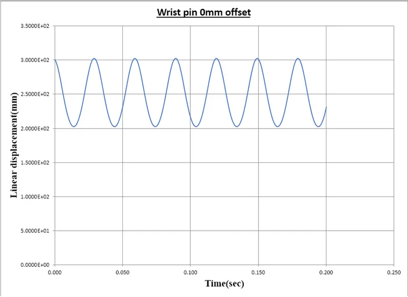
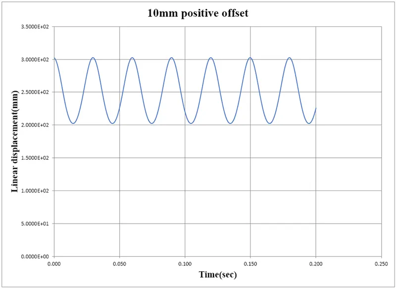
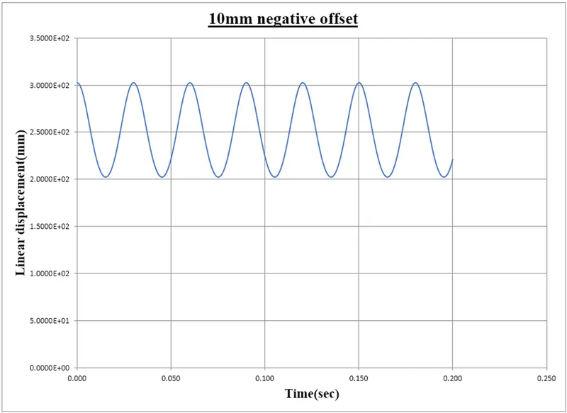
In the all three conditions the linear displacements are obtained with respect to time. That results are not exact one it just helps to understanding of piston movement in offset conditions. The following graph will help to understand.

In both negative and positive offset conditions the graph comes with similar profile because both offset values are equal. But in “0”mm offset the graph profile just expand with time because the piston moves up and down cover longer distance than other conditions. But the important factor is the friction in “0”mm offset is maximum compare with other two conditions.