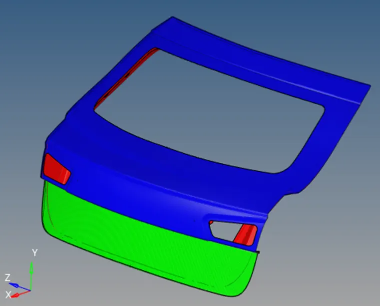
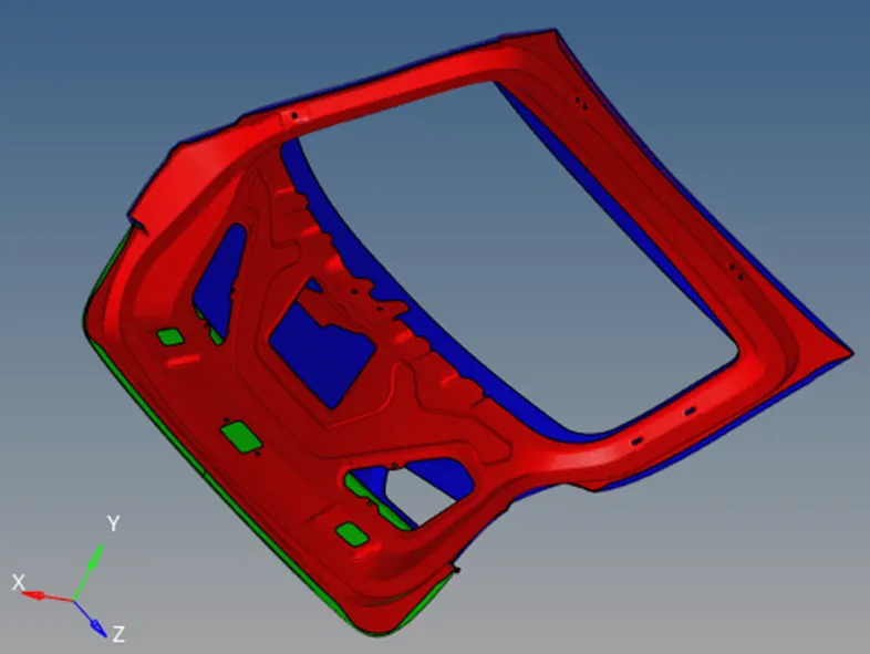
Manual mid-surfacing and Meshing of the backdoor geometry of a car using Hypermesh.
Aim:
To do manual mid-surfacing and meshing of the backdoor geometry of a car using Hypermesh.
Objective:
- To mesh the backdoor geometry of a car, keeping in mind quality parameters provided below:
Target Element size - 5 Units
|
S.N |
Quality Criteria |
Value |
|
1 |
Aspect Ratio |
5 |
|
2 |
Skewness |
45 |
|
3 |
Warping |
15 |
|
4 |
Taper |
0.5 |
|
5 |
Min. Length |
3 Units |
|
6 |
Max. Length |
7 Units |
|
7 |
Min angle Quad |
45 |
|
8 |
Max angle Quad |
135 |
|
9 |
Min angle Tria |
30 |
|
10 |
Max angle Tria |
110 |
|
10 |
Tria % |
15 |
- Attach the Hypermesh model files (.hm) with the challenge.
Imported Geometry:
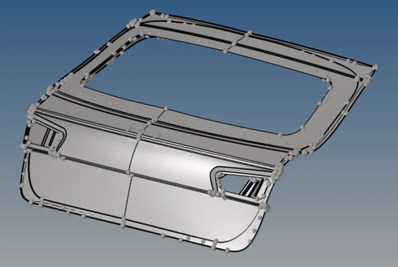
The imported geometry has 3 components:
- Upper body
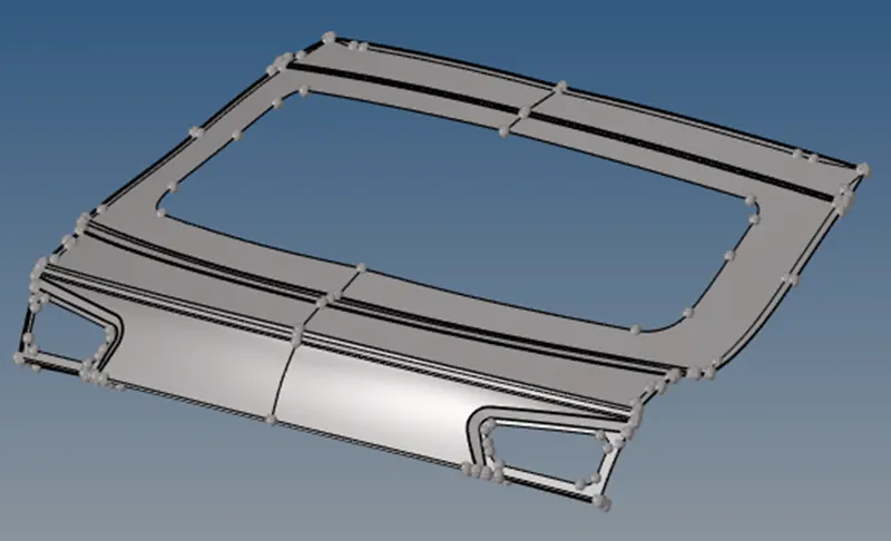
In topo view
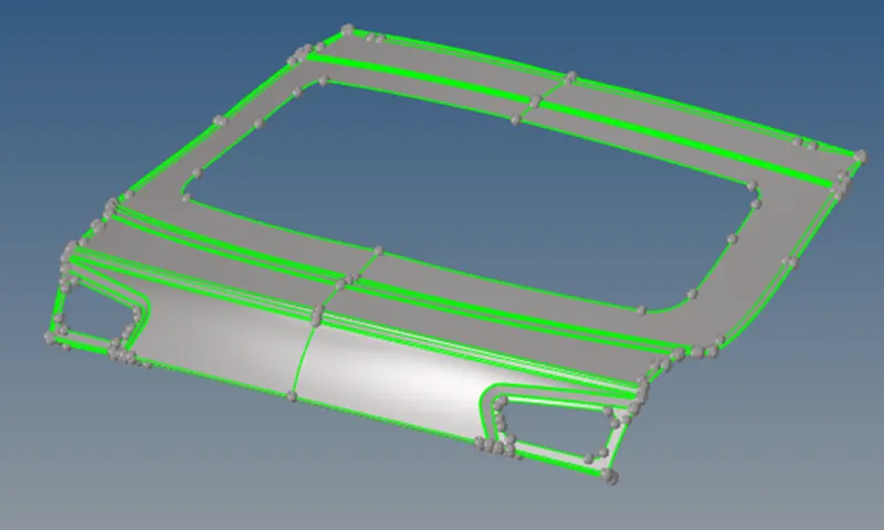
It can be seen that the upper body is a 2D surface.
- Lower body
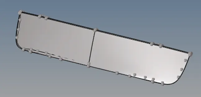
In topo view
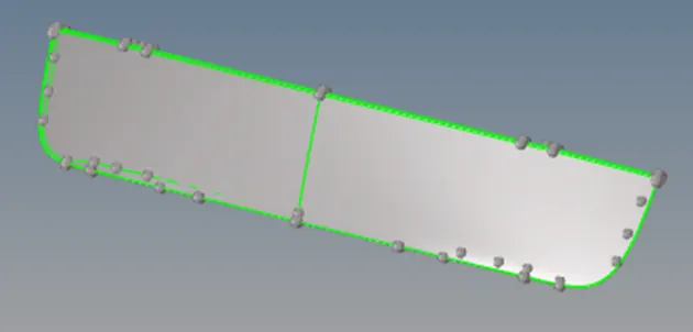
It can be seen that the lower body is a 2D surface.
- Inner Panel
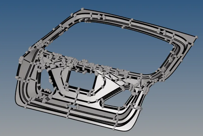
In topo view:
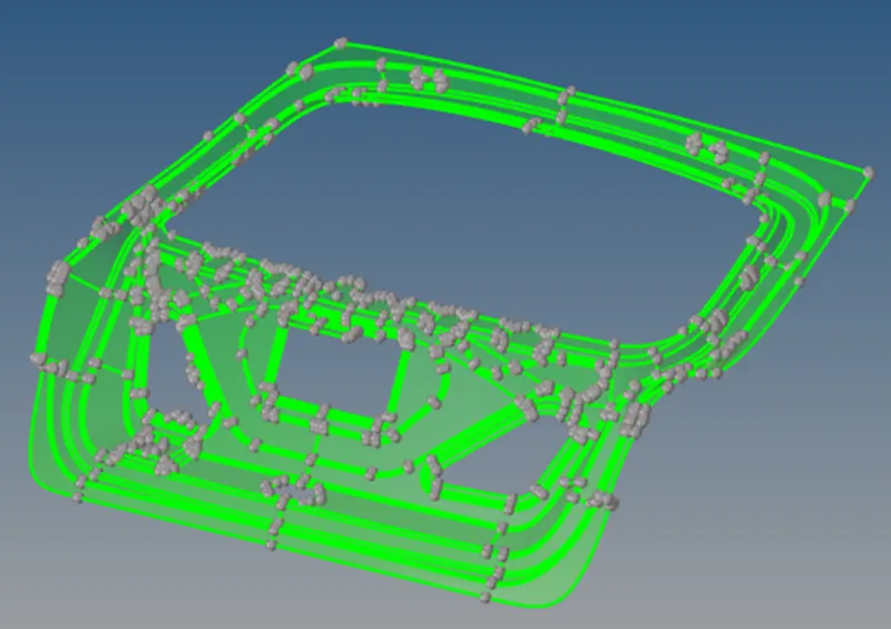
It can be observed that the inner panel is a solid. Since the bounding face is green, it belongs to one solid.
Setting mesh criteria as per our objective:
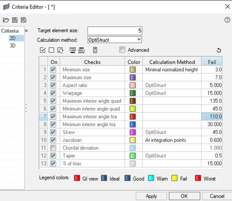
- Upper Body
Removing fillets b/w 1-5mm radius:
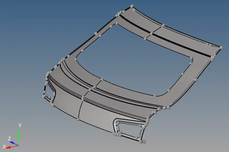
The component has no solid but it has lot of fillets. Depending upon industry standards, if the fillet is below 5mm we can delete it. If fillets are more than 8, 9 or 10 mm, then we have to mesh the fillet with 1,2,3 elements respectively.
Measuring the fillet distance
Press f4 (distance option)
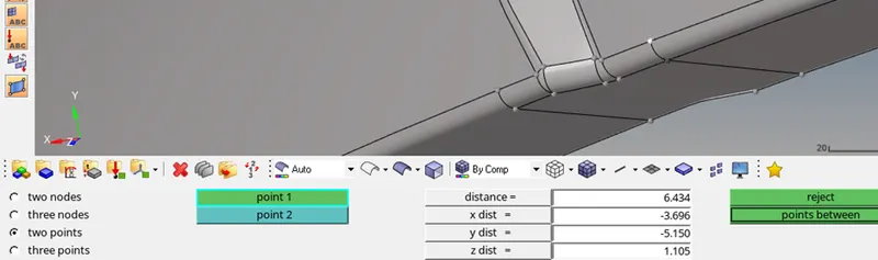
Defeaturing fillets bellow 5mm
Geom -> Defeature -> surface fillet


Select the ‘displayed’ option and then find.
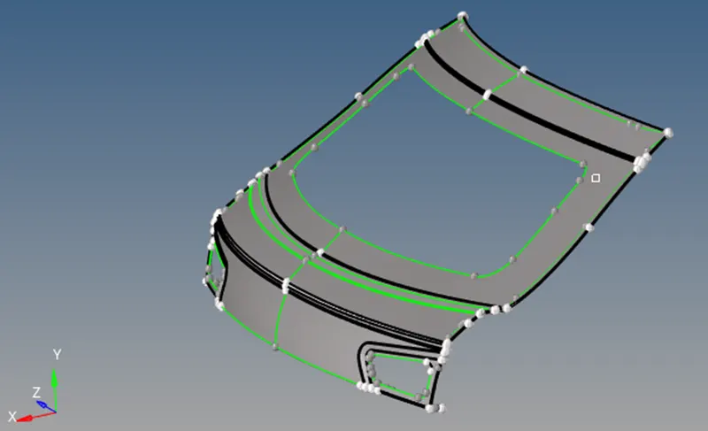
This will highlight all the fillets between 1 to 15mm.

Now select ‘remove’ to delete all the fillets.
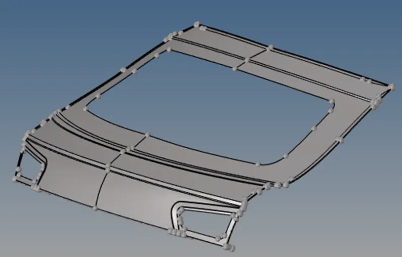
On removing the fillets by using hypermesh auto selection, we found that all the fillets are not removed & some surfaces have been distorted, as shown below.
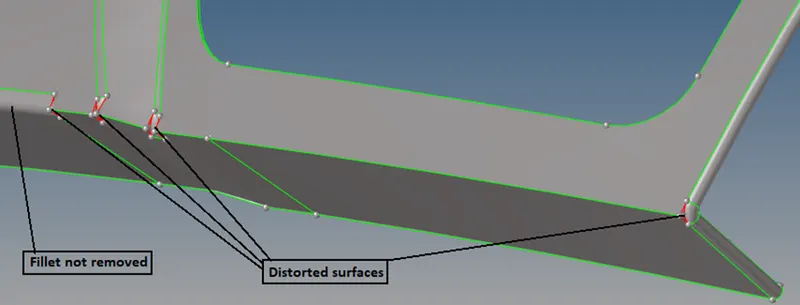
So, manually removing the fillet, by selecting the surface, in order to remove the remaining fillets.
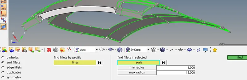
We can also select the fillet, and click on remove.
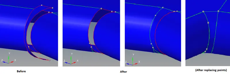
We can also ‘replace points’ to remove fillets as shown below:
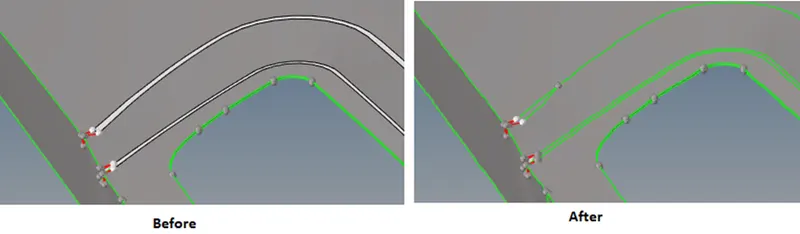
Even after removing majority of the fillets, we found that some of the distorted surfaces could not be healed. So, we will avoid removing fillets instead we will toggle unnecessary feature lines during geometric clean-up.
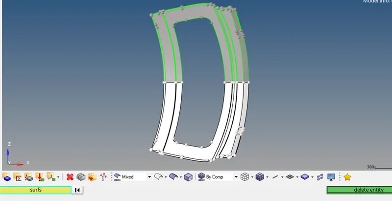
Deleting one half of the surface:
Geometric clean up:
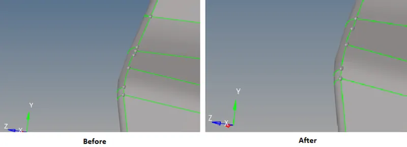
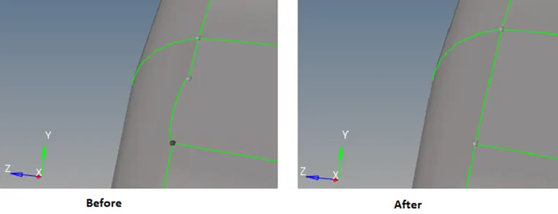
Replacing points:
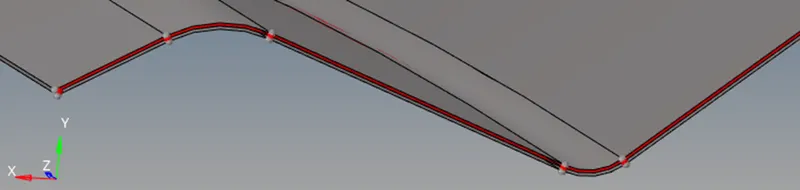
In order to make split line more uniform, unwanted points should be removed. This could be done by replacing one point with another.
Auto-clean up:
Go to geom-> auto-cleanup
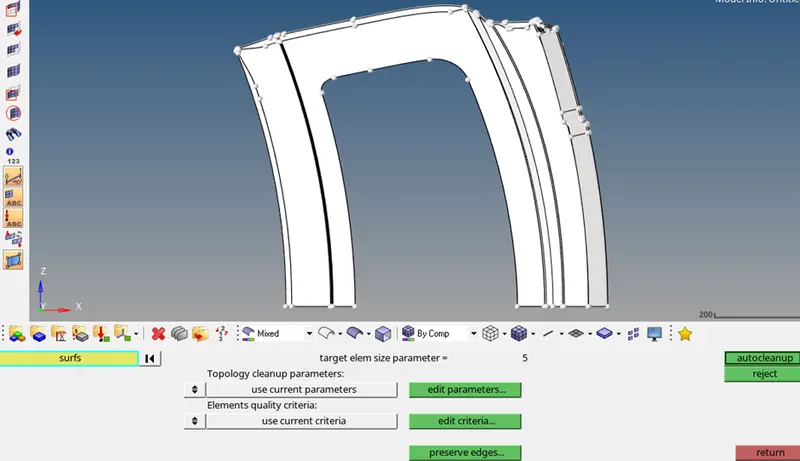
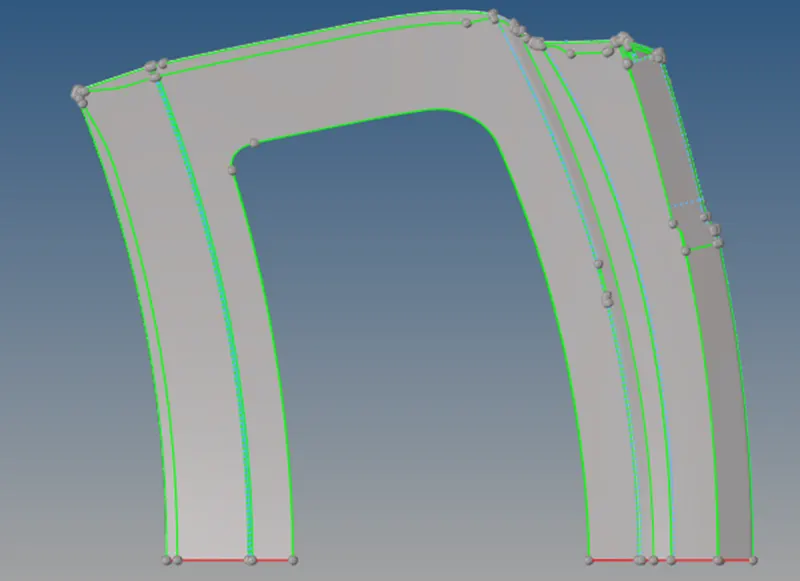
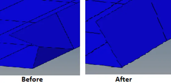
Since auto clean up has toggled some important feature line so we will reject the output and then toggle the unnecessary feature line manually.
Creating manual mid-surface by off-setting the surface:
When we deal with complex geometry with different thicknesses, this manual mid surfacing is very helpful.
Measure distance between two points:
Press f4
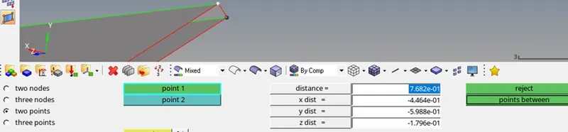
so we can see the distance between two points is 0.7682. Hence the surface should be off-setted by 0.3841
Creating new component namely ‘upper-mid surface’.
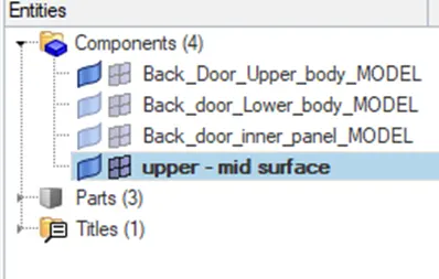
Now go to ‘geom’ -> surface edit
before off-setting duplicate the surface to current component.
Now select the surface and click on offset
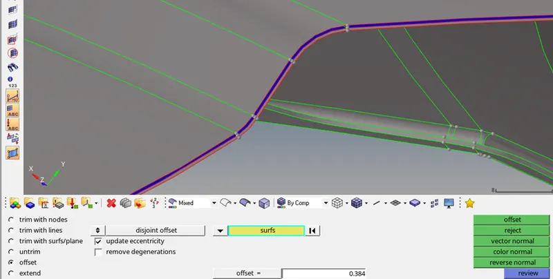
After inspection we can observe that a part of the surface is not off-set well (as shown below). And also, it is unable to move off-set in reverse direction. So, deleting and creating a fresh surface in its place.
To create a new surface, go to, geom -> surfaces -> spline/fillers.
Then select the line and surface will be created automatically.
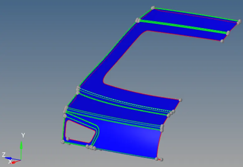
Final mid surface:
- Lower Body:
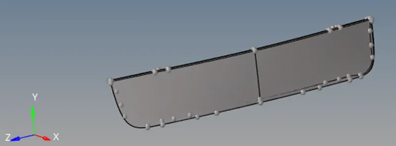
Deleting one half of the surface:
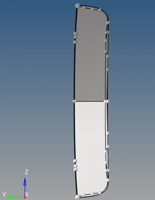
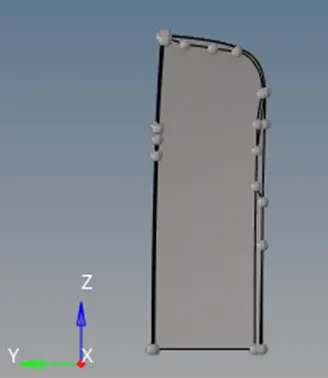
Geometric Clean-up:
After visual inspection, an unwanted surface and a missing surface can be seen.
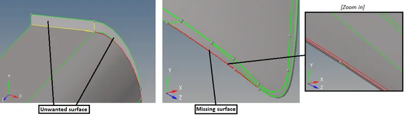
The ‘unwanted surface’ is deleated. ‘Missing surface’ is filled by going to surfaces->ruled, and then choosing the ‘line list’.
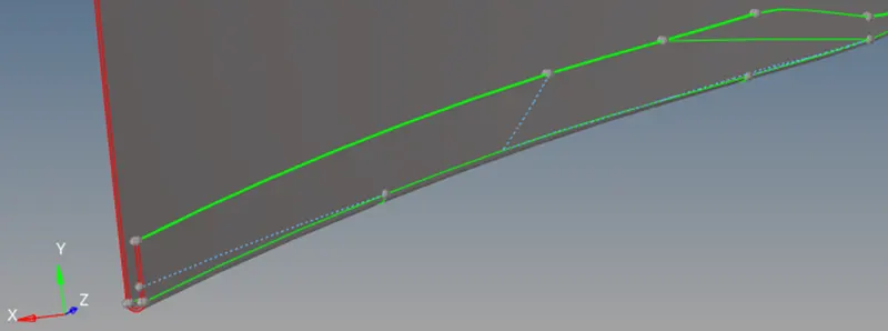
Now ‘toggle’ all unnecessery feature lines:
Creating manual mid surface by off-setting the surface:
When we deal with complex geometry with different thicknesses, this manual mid surfacing is very helpful.
Measure distance between two points:
Press f4
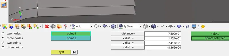
so, we can see the distance between two points is 0.75. Hence the surface should be off-set by 0.375.
Now, creating new component namely ‘lower-mid surface’.
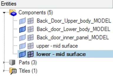
Now go to ‘geom’ -> surface edit
before off-setting, duplicate the selected surface to current component.
Now select all the required surfaces that are needed to be off-set and click on ‘offset’
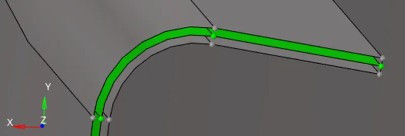
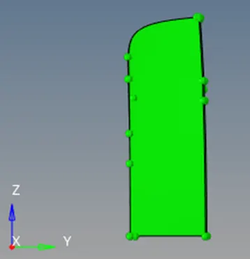
As wee can see a mid-surface have been created from the following image.
- Inner Panel:
Similar process could be repeated for the inner panel.
Extracting mid surface of the inner panel:
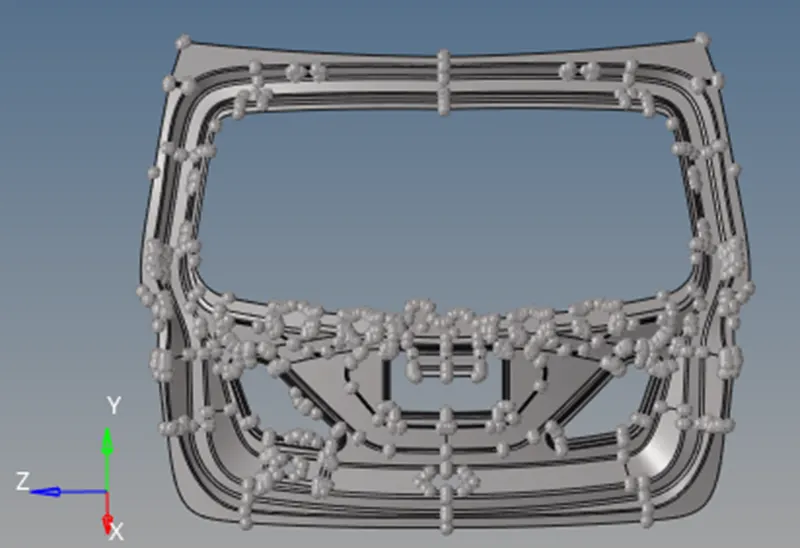
Since the model is a complete solid, we need to make it a shell element by deleting solids.
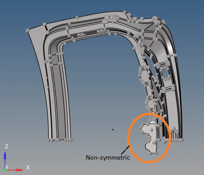
Deleting one half of the surface:
As we can see in the image below, a part of the model is not symmetric, hence it has not been meddled with.
Creating manual mid surface by off-setting the surface:
When we deal with complex geometry with different thicknesses, this manual mid surfacing is very helpful.
Measure distance between two points:
Press f4
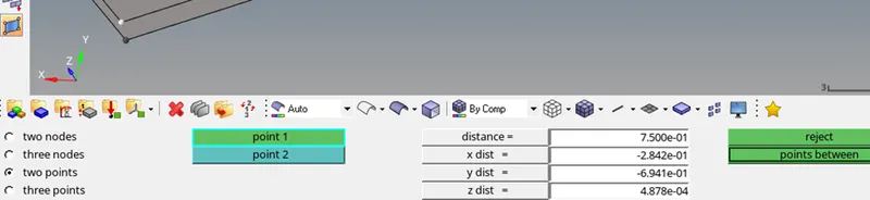
so, we can see the distance between two points is 0.75. Hence the surface should be off-set by 0.375.
Now, creating new component namely ‘inner panel - mid surface’.
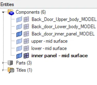
Now go to ‘geom’ -> surface edit
before off-setting, duplicate the selected surface to current component.
Now select all the required surfaces that are needed to be off-set and click on ‘offset’
As we can see a mid-surface have been created from the following image.
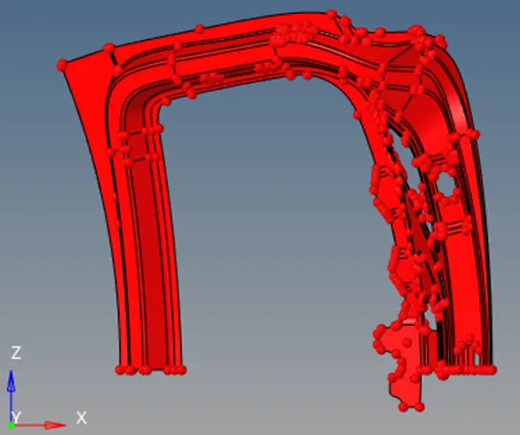
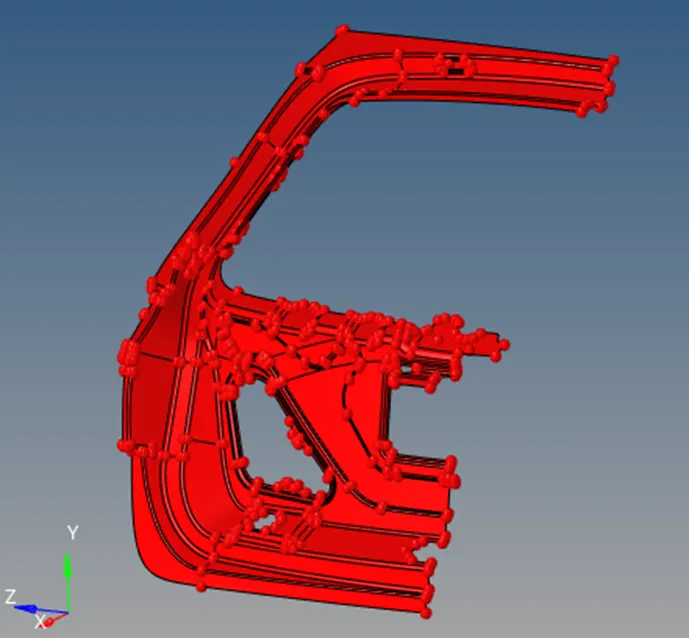
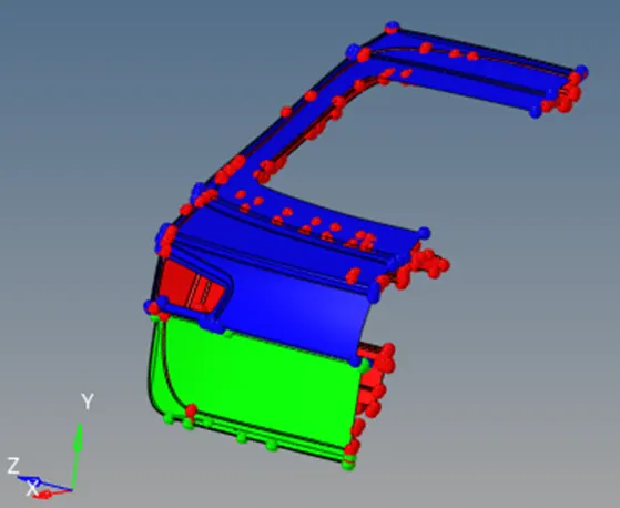
Mid surface of all three parts:
Meshing the mid surface:
Lower Body:
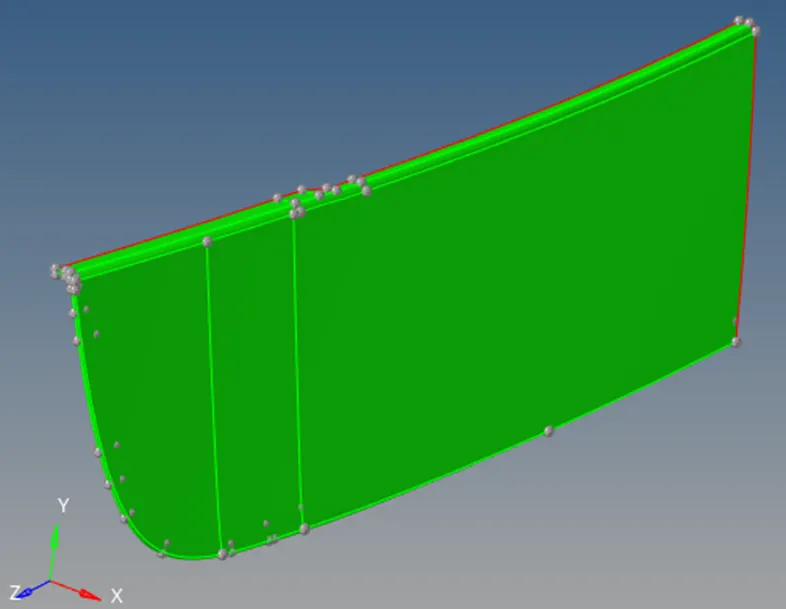
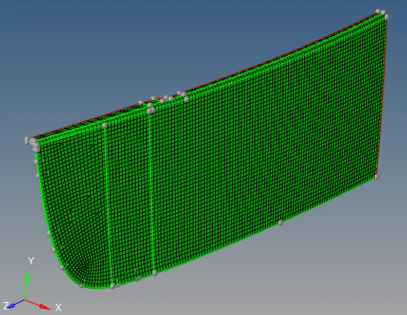
Upper Body:
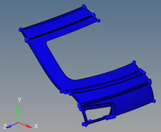
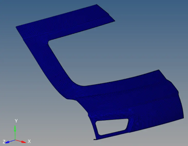
To make the mesh smooth following functions could be performed:
- Re-mesh reverse tria
- Dragging trias
- Smoothing
- Deleting and re-creating elements using ‘element edit’
Inner panel:
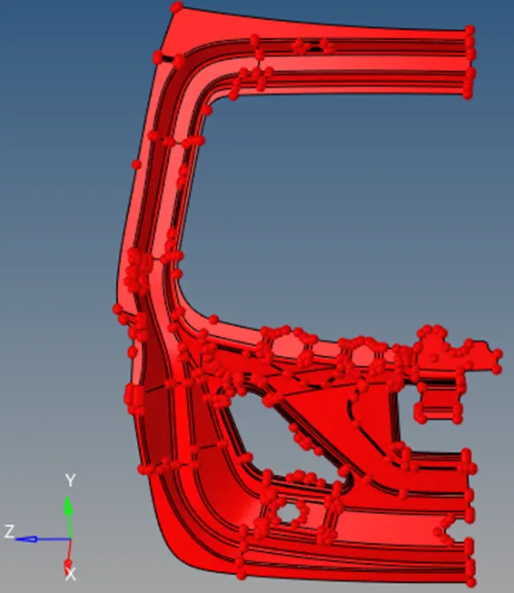
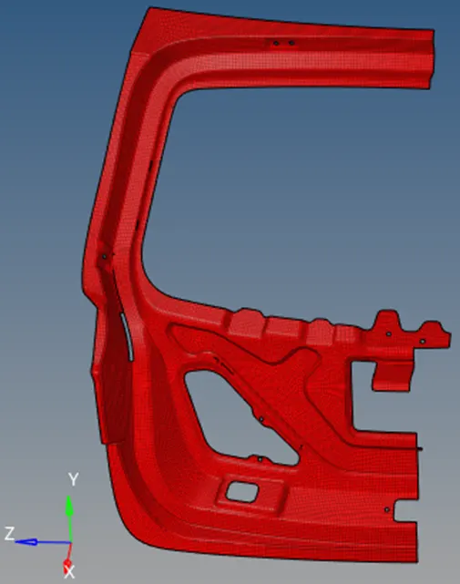
- Reflecting to get entire mesh:
After meshing one half, we can reflect and duplicate its mesh element along an axis to get the entire meshed geometry.
But before reflecting make the component your current component.
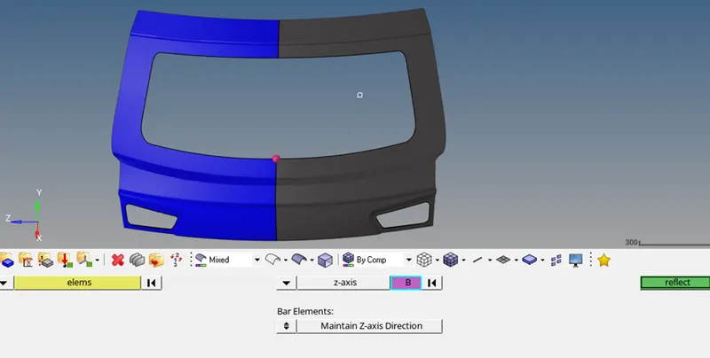
Go to, Edges -> find edges
Edges will be marked by ‘red line’.
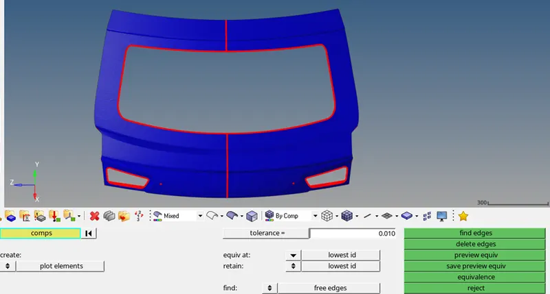
Click on ‘equivalence’ to fill the edge.
If the ‘equivalence’ does no work.
Go to 2D - > replace
Check equivalence and midpoint box.
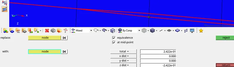
Use red edge line as a guide line to replace the nodes.
While replacing the nodes Hypermesh may throw some error saying “the mesh will be distorted if continued’. Click ‘no’. come back and select the ‘replace’ option again. Try switching the nodes to be replaced this time. Continue till all the nodes are replaced.

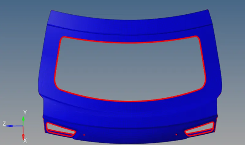
After replacing all edges, go to -> tools- -> edges -> find edges.
The free edge has been filled.
Similarly:
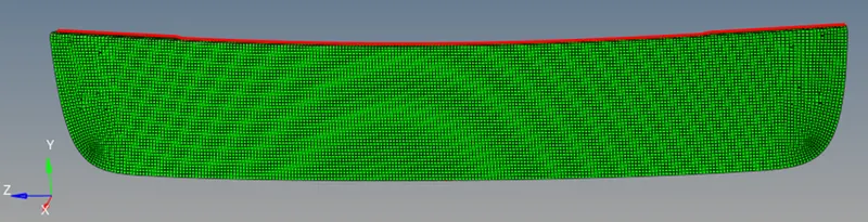
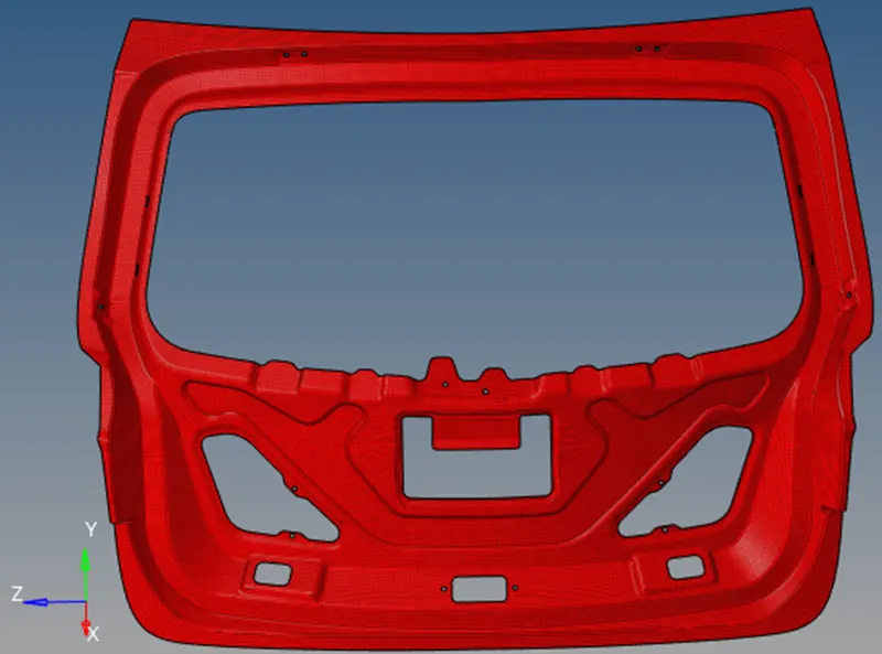
- Final Mesh: