Internal Geneva Mechanism
MOTION ANALYSIS OF AN INTERNAL GENEVA MECHANISM
AIM
Create 3D models for internal Geneva driven and driver wheels and perform motion analysis with different driver wheel speeds. Also using this speed difference find out the kinematic characteristic’s and obtain some plots.
INTRODUCTION
One of the most commonly used devices for producing intermittent rotary motion, characterized by alternate periods of motion and rest with no reversal in direction. It is also used for indexing (i.e., rotating a shaft through a prescribed angle). The name Geneva drive is derived from the devices earliest application in mechanical watches, which were popularized in Geneva, being the classical origin of watchmaking industry. The mechanism is frequently used in mechanical watches, since it can be made small and is able to withstand substantial mechanical stress. The Geneva drive is also called a "Maltese cross mechanism" due to the visual resemblance when the rotating wheel has four spokes. In the most common arrangement of the Geneva drive, the client wheel has four slots and thus advances the drive by one step at a time (each step being 90 degrees) for each full rotation of the master wheel. If the steered wheel has n slots, it advances by 360°/n per full rotation of the propeller wheel. Because the mechanism needs to be well lubricated, it is often enclosed in an oil capsule.
THEORY
Motion study is a systematic way of determining the best method of doing the work by scrutinizing the motions made by the worker or the machine. The Geneva drive or Maltese cross is a gear mechanism that translates a continuous rotation movement into intermittent rotary motion. The rotating drive wheel is usually equipped with a pin that reaches into a slot located in the other wheel (driven wheel) that advances it by one step at a time. The drive wheel also has an elevated circular blocking disc that "locks" the rotating driven wheel in position between steps. There are three different standard type Geneva mechanisms known as "External", “Internal" and "Spherical" Geneva mechanisms. Each of these has advantages and disadvantages when compared to the other types. Depending on the type of operation in demand, a decision may be made on the selection of the compatible type.
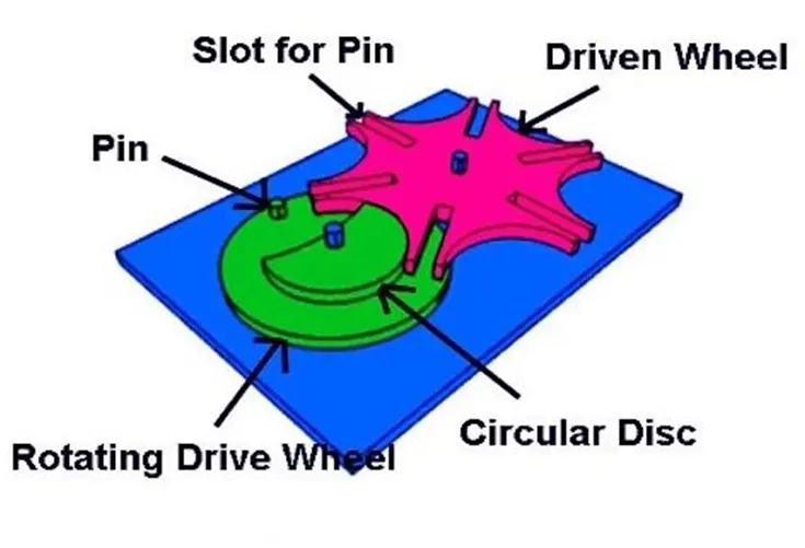
INTERNAL GENEVA MECHANISM
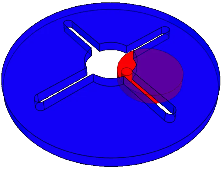
Here we are going to study about internal Geneva mechanism. An internal Geneva drive is a variant on the design. The axis of the drive wheel of the internal drive can have a bearing only on one side. The angle by which the drive wheel has to rotate to effect one step rotation of the driven wheel is always smaller than 180° in an external Geneva drive and always greater than 180° in an internal one, where the switch time is therefore greater than the time the driven wheel stands still.
The "indexing" period starts from the initial engagement of the driver pin with one of the slots of the driven member/wheel. This period ends with the complete disengagement of the pin from the slot. The "dwell" period starts at the end of the index period and ends exactly at the initial engagement of the driver pin with the "next" (ready to be indexed) slot. While the driver experiences constant angular motion, the driven member can only rotate during the index period.
KINEMATIC CHARACTERISTICS
Kinematic analysis is the process of measuring the kinematic quantities used to describe motion. In engineering, for instance, kinematic analysis may be used to find the range of movement for a given mechanism and working in reverse, using kinematic synthesis to design a mechanism for a desired range of motion. In addition, kinematics applies algebraic geometry to the study of the mechanical advantage of a mechanical system or mechanism.
(i)Angular displacement: It is defined as “the angle in radians (degrees, revolutions) through which a point or line has been rotated in a specified sense about a specified axis”. It is the angle of the movement of a body in a circular path.
⸫ θ=l/r
For example, if a body rotates 360° around a circle of radius r, the angular displacement is given by the distance travelled around the circumference which is 2πr divided by the radius: θ=2πr/r which easily simplifies to: θ=2π. Therefore, 1 revolution is 2π radians.
(ii)Angular velocity: The angular velocity is the rate at which displacement is changing with respect to the time in circular motion. In the simplest case of circular motion at radius r, with position given by the angular displacement ϕ(t) from the x-axis, the orbital angular velocity is the rate of change of angle with respect to time:
⸫ ω=dϕ/dt
(iii)Angular acceleration: Angular Acceleration is defined as the time rate of change of angular velocity. It is usually expressed in radians per second per second. The angular acceleration is also known as rotational acceleration.
⸫ α=dω/dt
STUDY SETUP
- Type of study: (motion analysis) It gives the most realistic simulation, taking into account all available types of motion objects and providing accurate and numerical results.
- Motor: set the driving wheel as motor for rotate at constant speed about its center axis with different speeds.
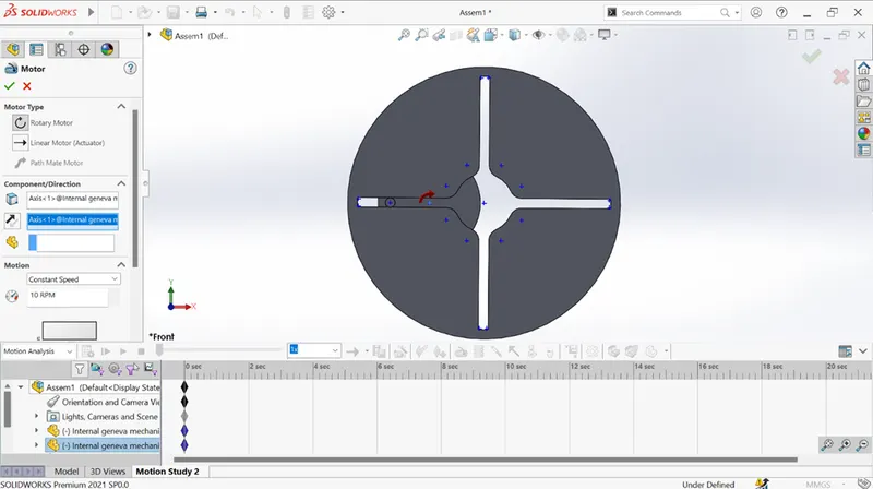
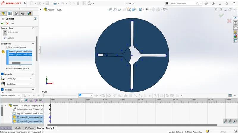
- Contact: simulate contact between driven and driving wheels of Geneva mechanism for ensure the contact between pin and slot. And steel material had been used for both the wheels to use present values for friction and elastic properties.
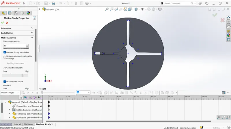
- Property: to specifies the simulation properties for this motion study. Frame per second is 60 for 10rpm speed and similar to 120fps for 20rpm speed.
RESULT
The motion analysis for internal Geneva mechanism was completed after well designed 3D model for it. Using the proper mates, the final assembly of internal Geneva also finished. Center axis distance between both wheel is 226.27mm and it was taken as 225mm for the requirement. The center of driving wheel was taken as motor that’s rotate at clockwise direction at 10 and 20rpm. Contact for both wheels also set. Because without this one the driving wheel will rotate separately, not rotates the driven wheel. Finally, the plots for this study are obtained.
Case(i): speed=10rpm(60fps) without precision
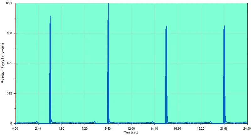
Contact force
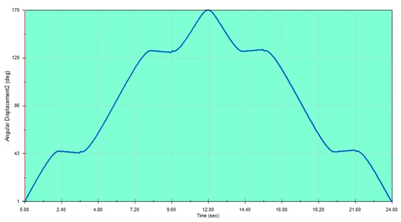
Angular displacement of driven wheel
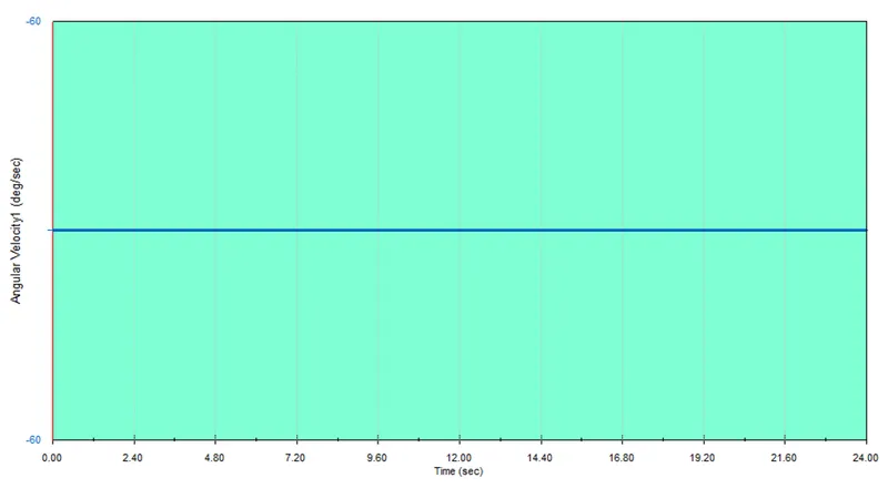
Angular velocity of driving wheel
Case(ii): speed=20rpm(120fps) without precision
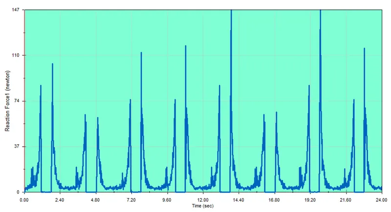
Contact force
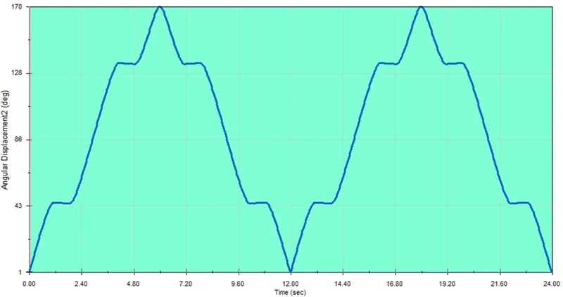
Angular displacement of driven wheel
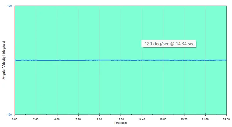
Angular velocity of driving wheel
Case(iii): speed=10rpm(60fps) with precision
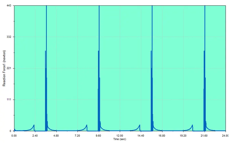
Contact force
Case(iv): speed=20rpm(120fps) with precision
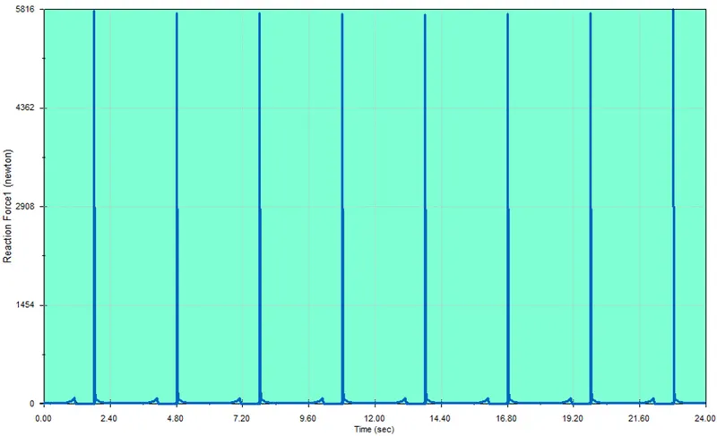
Contact force
OBSERVATION
- The contact force always maximum while first time the pin and the slot contact each other. After that the force almost zero because the driven wheel rotate freely duo to initial force by pin and slot. You can see clearly on contact force without precision plots having ups and down peak, while with precision the peaks almost meet at similar value. Also, the small peaks are arrived during the pin leaves the slot every time.
- Angular displacement of driven wheel is constant during the pin and the slot without contact. After that it rotate 90° about center axis. If we set the driving wheel speed 20rpm, the one revolution of driven wheel is completed in 12sec.
- Angular velocity of driving wheel is always constant. But the minimum distraction will happen during contact occurred by pin and slot.