Induction motor characteristics and speed control methods
Aim- Induction motor characteristics and speed control methods
Objectives-
- To understand the contrast between induction motor operation and mechanical clutch.
- To calculate the starting time of IM with given parameters
- To obtain the equilibrium points and determine the stability of the induction motor.
- To make a MATLAB script file for plotting speed-torque characteristics of IM for frequency control method.
Introduction
Induction motors are widely used in the industrial applications because they require lower maintenance and are more efficient than DC drives. With the availability of IGBTs and transistors induction motors have found place requiring variable speed applications. They are used in variety of applications such as fan, cranes, conveyers, underground installations and electric vehicles.
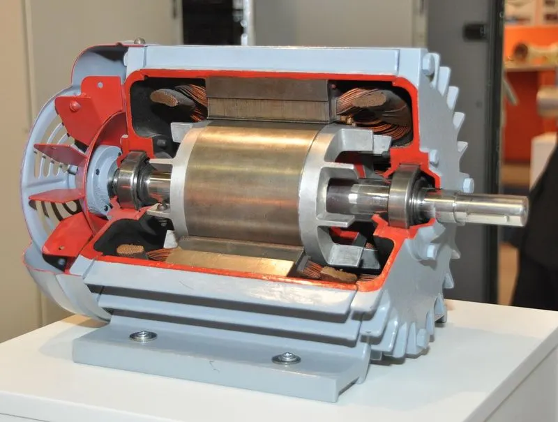 |
| Figure 1: Cut section of Induction motor |
Analogy of Induction motor operation with clutch
Clutch operation
A clutch is a mechanical device that engages and disengages the power transmission with input shaft and the output shaft.
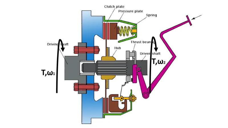 |
| Figure 2: Single-plate clutch |
In the above figure, the torque is being transferred between driving and the driven shafts. The angular speed of the shafts is not equal due to the presence of various friction losses, this difference of speed is called slip.
| `s=(ω_1-ω_2)/ω_1` |
(1) |
|
| `ω_2=ω_1 (1-s)` |
(2) |
Loss in clutch-
| `"loss=input-output"` | ||
| `loss=Tω_1-Tω_2` | ||
| `loss=Tω_1-T{ω_1 (1-s)}` | ||
| `loss=T(1-s)` |
Induction motor operation
Induction motor operates in a similar fashion
 |
|
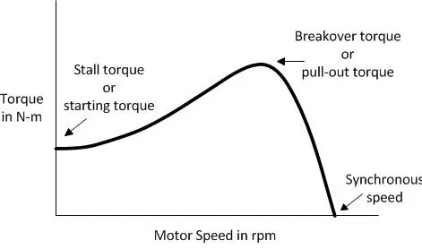
Figure 3: Speed-torque curve of an Induction motor |
The above figure shows the working of an induction motor, from stating torque point to the pull-out torque point the motor is not operational to overcome the l`T_m=15+0.5ω_m`oad which is similar to clutch being disengaged. After pull-out torque to synchronous speed point the induction motor is operational with load and it satisfies the steady state stability condition which contrasts with clutch engagement situation.
This is exactly similar to the clutch, where the load is engaged when the speed rises. The load torque is also higher than the engine torque, hence it limits the speed by not reaching infinite values and also doesn’t retard the engine to zero.
Therefore, for an induction motor the rotor speed is given by
| `ω_m=ω_ms (1-s)` |
(3) |
Starting time of Induction motor
Starting time of motor is defined as the time taken by the motor to fully engage the load and start functioning. It is actually the time taken by the motor to reach from starting torque point to the break over torque point.
Given parameters-
|
Moment of inertia (J) |
`J=10 kg-m^2` |
|
Motor torque (Tm) |
`T_m=15+0.5ω_m` |
|
Load torque (Tl) |
`T_l=5+0.6ω_m` |
A motor-load system is described by the following equation-
| `T_m-T_l=d/dt (Jω_m )=J (dω_m)/dt+ω_m dJ/dt` |
(4) |
For constant inertia drives it becomes
| `T_m=T_l+J (dω_m)/dt` |
(5) |
Consider steady-state
| `T_m=T_l` | ||
| `15+0.5ω_m=5+0.6ω_m` | ||
| `ω_m=100 rps` |
Thus
| `(dω_m)/dt=(T_m-T_l)/J=1-0.01ω_m` |
(6) |
A slip of 5% is assumed in the system.
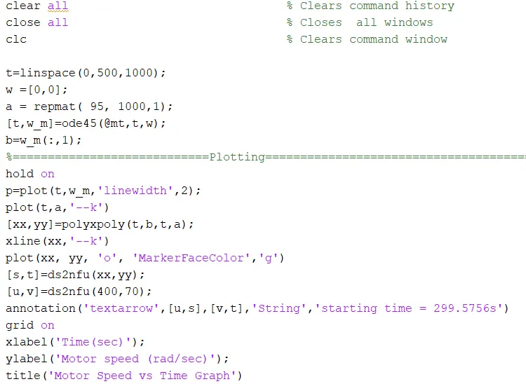
In MATLAB we can solve this differential equation using ode45 solver and can plot a curve for the same.
 |
|
Figure 4: Motor-Load system modelled in MATLAB |
 |
|
Figure 5: MATLAB script for solving the differential equation |
 |
|
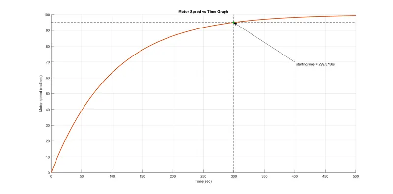
Figure 6: Image showing the starting time of Induction motor |
Apart from doing it in a graphical way we can do it by integrating the motor-load system equation as well
After rearranging the equation-
| `dt=(Jdω_m)/(T_m-T_l )` |
(7) |
Integrating both sides
| `t=∫_(ω_1)^(ω_2)(Jdω_m)/(T_m-T_l )` |
(8) |
Now substituting the values in the above equation
| `t=∫_(ω_1)^(ω_2)(1/(1-0.01ω_m )) dω_m` |
(9) |
Let’s assume the slip to be 5% therefore the speed with slip will be 95 rad/s.
Now,
| `t=∫_0^95(1/(1-0.01ω_m )) dω_m` |
(10) |
 |
|
Figure 7: Integration using MATLAB |
 |
|
Figure 8: Starting time of Induction motor |
Equilibrium points and Stability of Induction motor
Stability of a system can be defined as the ability of a system to regain equilibrium after disturbance. Equilibrium speed of a motor-load system is obtained when motor torque equals the load torque. Drive will operate in steady-state at this speed, provided it is the speed of stable equilibrium. Concept of Steady State Stability of Drive has been developed to readily evaluate the stability of an equilibrium point from the steady-state speed-torque curves of the motor and load, thus avoiding solution of differential equations valid for transient operation of the drive. [1]
Consider the dynamic equation of motion of Induction motor drive with constant moment of inertia.
| `T_m-T_l=J (dω_m)/dt` |
(11) |
Let a small change in speed,`Δω_m` , results `ΔT_m` in `ΔT_l` and change in `T_m and T_l` respectively.
| `(T_m+ΔT_m)-(T_l+ΔT_l)=J (dω_m)/dt+J (dΔω_m)/dt` |
(12) |
Subtracting 11 from 12 we get
|
`ΔT_m-ΔT_l=J (dΔω_m)/dt` |
(13) |
For small change, we can write
|
`(dT_m)/(dω) Δω_m-(dT_l)/(dω) Δω_m=J (dΔω_m)/dt` |
(14) |
|
| `J (dΔω_m)/dt+((dT_l)/(dω)-(dT_m)/(dω)) Δω_m=0` |
(15) |
The equation obtained is a first order linear differential equation
If initial deviation in speed at `t = 0` be `(Δω_m)_0`then the solution
|
`Δω_m=(Δω_m)_0e^{-1/J ((dT_l)/(dω)-(dT_m)/(dω))t}` |
(16) |
An operating point will be stable when approaches zero as t approaches infinity. For this to happen the exponent in must be negative.
Thus, for stability
|
`(dT_l)/(dω)-(dT_m)/(dω)>0` |
(17) |
Given parameters
|
Motor torque (Tm) |
`T_m=1+2ω_m` |
|
Load torque (Tl) |
`T_l=3√(ω_m )` |
For steady-state
|
`T_m=T_l` |
||
|
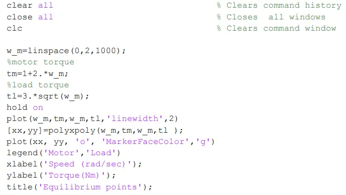
`1+2ω_m=3√(ω_m )` |
||
|
`4ω_m^2-5ω_m+1=0` |
Thus operating points are-
|
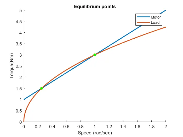
`ω_m=1 or 0.25 " rad/sec"` |
From the stability condition equation
|
`T_m=1+2ω_m` |
||
|
`(dT_m)/(dω)=2` |
||
|
`T_l=3√(ω_m )` |
||
|
`(dT_l)/(dω)=3/(2√(ω_m ))` |
||
|
`3/(2√(ω_m ))-2>0` |
When `ω_m=0.25`
|
`3/(2√0.25)-2>0` |
||
|
`2.2412640>0` |
When`w_m=1`
|
`3/(2√1)-2>0` |
||
|
`-0.5>0` |
Thus only `ω_m=0.25 " rad/sec"` is a stable operating point for this induction motor.
 |
|
Figure 9: MATLAB script for finding operating point |
 |
|
Figure 10: Speed torque characteristics showing operating points of motor |
Induction motor control using variable frequency method
Equivalent circuit of Induction motor
Equivalent circuit analysis enables us to examine the characteristics of the machine and predict its operating behaviour.
Given below is the equivalent circuit for an Induction motor.
 |
|
Figure 11: Equivalent Circuit of Induction motor |
Here,
|
R1 |
Stator resistance |
|
R2 |
Rotor resistance with respect to stator |
|
X1 |
Stator leakage reactance |
|
Xm |
Magnetising reactance to cross air gap |
|
Rc |
Core losses (eddy current & hysteresis) |
|
X2 |
Rotor reactance with respect to stator |
The torque developed by induction motor is given by-
| `T=3/(ω_(ms) ) ((V^2 R_2∕s)/((R_1+R_2/s)^2+(X_1+X_2 )^2 ))` |
(18) |
Where `ω_(ms)` the synchronous speed in rad/sec, V is the voltage applied to the stator, `R_2` and `X_2` are rotor resistance and reactance with respect to stator respectively, `R_1` and `X_1` are stator resistance and reactance respectively.
Slip is defined by
| `s=(ω_(ms)-ω_m)/ω_(ms)` |
(19) |
Where `ω_(ms)` & `ω_m` are synchronous and rotor speed respectively. Further
| `ω_(ms)=(4πf)/P` |
(20) |
Where f and P are frequency and number of poles respectively.
Torque-Speed control with variable frequency control
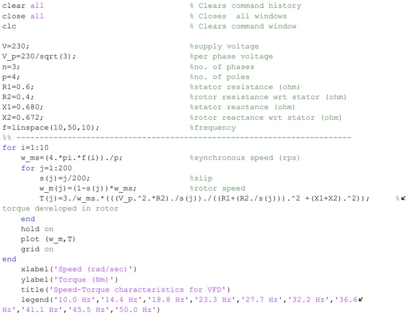
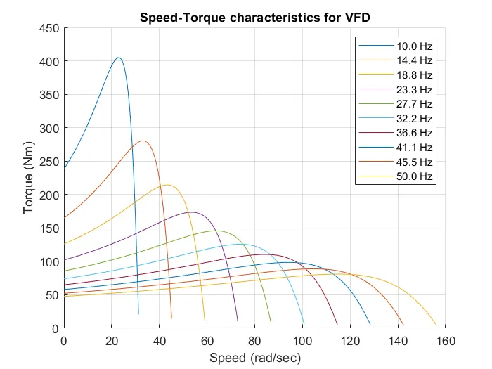
By varying the frequency we can change synchronous speed therefore, motor speed can be controlled by varying supply frequency. The voltage induced in stator is proportional to the product of supply frequency and air gap flux. The operating flux φ is kept constant to reduce the core and stator copper losses.
| `E=4.4K_c∅fN_(st)` |
(21) |
where `K_c` is the machine constant, E is the induced voltage in the stator, φ is the rated flux in the air-gap, `N_(st)`is the number of turns in the stator.
 |
|
Figure 12: Induction motor control using variable frequency control |
 |
|
Figure 13: Speed torque characteristics for variable frequency drive |
References
- K. Dubey. Fundamentals of Electrical Drives, Alpha Science International Ltd., 2001.
- Michelle Hirsch (2021). Data space to figure units conversion (https://github.com/michellehirsch/MATLAB-Dataspace-to-Figure-Units), GitHub. Retrieved May 2, 2021.
- (2018, December 22). Steady State Stability of Drive. EEEGUIDE.COM.https://www.eeeguide.com/steady-state-stability-of-drive/.
- Daware , K. (n.d.). Speed control methods of induction motor. electricaleasy.com. https://www.electricaleasy.com/2014/02/speed-control-methods-of-induction-motor.html.
- McFadyen, S. (2014, May 13). Induction Motor Equivalent Circuit . myElectrical.com. https://myelectrical.com/notes/entryid/251/induction-motor-equivalent-circuit.
- Jeffry. (2021, February 24). Speed vs torque characteristics of frequency controlled Induction motor using MATLAB. skill-lync.com. https://skill-lync.com/projects/speed-vs-torque-characteristics-of-frequency-controlled-induction-motor-using-matlab