Independent Research Project
Aim- To study the aerodynamics of airfoil body by varying the angle of attack.
Introduction-
Airfoil-
Airfoil, also spelled Aerofoil, shaped surface, such as an airplane wing, tail, or propeller blade, that produces lift and drag when moved through the air. An airfoil produces a lifting force that acts at right angles to the airstream and a dragging force that acts in the same direction as the airstream.
A solid body moving through a fluid produces an aerodynamic force. The component of this force perpendicular to the relative freestream velocity is called lift. The component parallel to the relative freestream velocity is called drag. An airfoil is a streamlined shape that is capable of generating significantly more lift than drag.[1] Airfoils designed for use at different speeds differ in their geometry: those for subsonic flight generally have a rounded leading edge, while those designed for supersonic flight tend to be slimmer with a sharp leading edge. All have a sharp trailing edge. Foils of similar function designed with water as the working fluid are called hydrofoils.
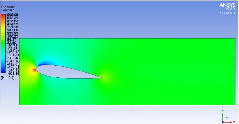
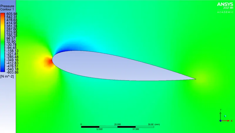
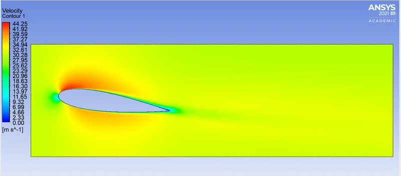
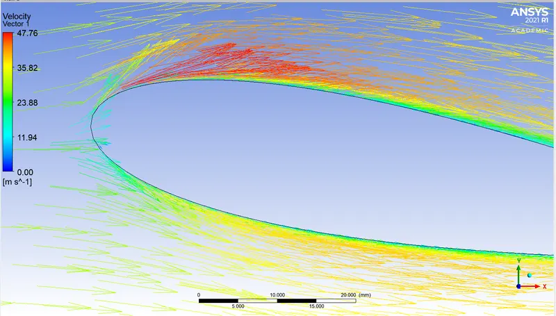
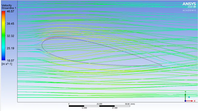
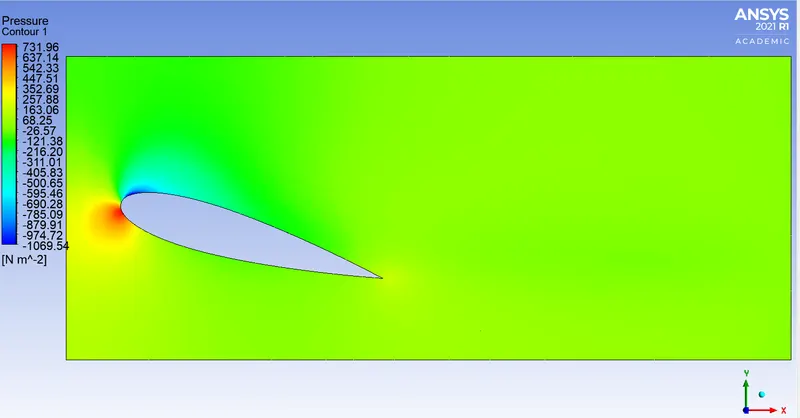
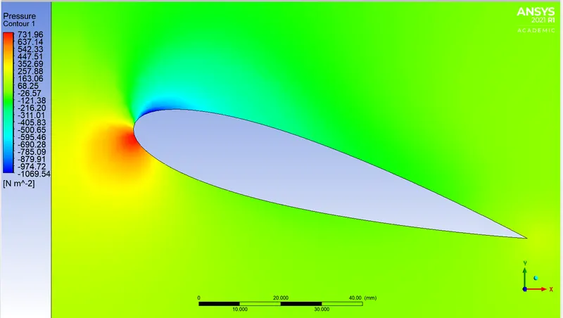
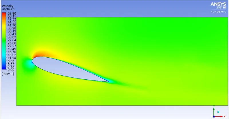
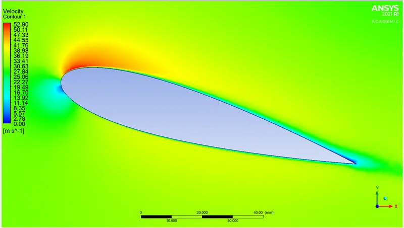
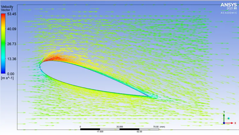
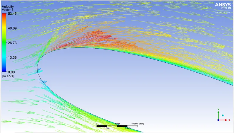
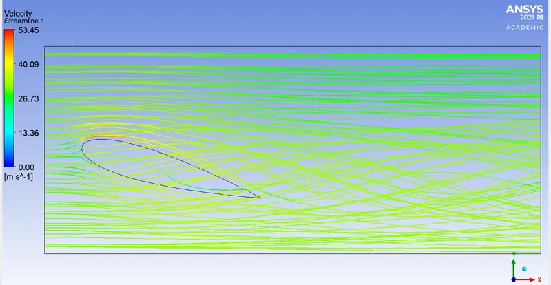
The lift on an airfoil is primarily the result of its angle of attack. When oriented at a suitable angle, the airfoil deflects the oncoming air (for fixed-wing aircraft, a downward force), resulting in a force on the airfoil in the direction opposite to the deflection. This force is known as aerodynamic force and can be resolved into two components: lift and drag. Most foil shapes require a positive angle of attack to generate lift, but cambered airfoils can generate lift at zero angle of attack. This "turning" of the air in the vicinity of the airfoil creates curved streamlines, resulting in lower pressure on one side and higher pressure on the other. This pressure difference is accompanied by a velocity difference, via Bernoulli's principle, so the resulting flowfield about the airfoil has a higher average velocity on the upper surface than on the lower surface.
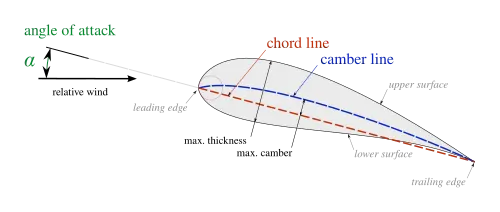
The various terms related to airfoils are defined below:
- The suction surface (a.k.a. upper surface) is generally associated with higher velocity and lower static pressure.
- The pressure surface (a.k.a. lower surface) has a comparatively higher static pressure than the suction surface. The pressure gradient between these two surfaces contributes to the lift force generated for a given airfoil.
The geometry of the airfoil is described with a variety of terms :
- The leading edge is the point at the front of the airfoil that has maximum curvature (minimum radius).[7]
- The trailing edge is defined similarly as the point of maximum curvature at the rear of the airfoil.
- The chord line is the straight line connecting leading and trailing edges. The chord length, or simply chord,
 , is the length of the chord line. That is the reference dimension of the airfoil section.
Different definitions of airfoil thickness-
The shape of the airfoil is defined using the following geometrical parameters:
- The mean camber line or mean line is the locus of points midway between the upper and lower surfaces. Its shape depends on the thickness distribution along the chord;
- The thickness of an airfoil varies along the chord. It may be measured in either of two ways:
- Thickness measured perpendicular to the camber line. This is sometimes described as the "American convention"
- Thickness measured perpendicular to the chord line. This is sometimes described as the "British convention".
Some important parameters to describe an airfoil's shape are its camber and its thickness. For example, an airfoil of the NACA 4-digit series such as the NACA 2415 (to be read as 2 – 4 – 15) describes an airfoil with a camber of 0.02 chord located at 0.40 chord, with 0.15 chord of maximum thickness.
Finally, important concepts used to describe the airfoil's behaviour when moving through a fluid are:
- The aerodynamic center, which is the chord-wise length about which the pitching moment is independent of the lift coefficient and the angle of attack.
- The center of pressure, which is the chord-wise location about which the pitching moment is zero.
Angle of attack-
The angle of attack (AOA) is the angle at which the chord of an aircraft's wing meets the relative wind. The chord is a straight line from the leading edge to the trailing edge.
In fluid dynamics, angle of attack (AOA, α, or  ) is the angle between a reference line on a body (often the chord line of an airfoil) and the vector representing the relative motion between the body and the fluid through which it is moving.[1] Angle of attack is the angle between the body's reference line and the oncoming flow.
In aerodynamics, angle of attack specifies the angle between the chord line of the wing of a fixed-wing aircraft and the vector representing the relative motion between the aircraft and the atmosphere. Since a wing can have twist, a chord line of the whole wing may not be definable, so an alternate reference line is simply defined. Often, the chord line of the root of the wing is chosen as the reference line. Another choice is to use a horizontal line on the fuselage as the reference line (and also as the longitudinal axis).
Theory-
It is fact of common experience that a body in motion through a fluid experiences a resultant force mainly a resistance to a motion. A class of body exists, for which the component of resultant force normal to the direction of motion is many times greater than the component resisting the motion.
An airfoil is a streamlined body found in airplanes, propellers, turbines and many other applications. When an airfoil body is passing through any fluid it produces an aerodynamic force which is due to pressure distribution and shear stress distribution over the body surface. This aerodynamic force can be resolved into two components known as lift and drag. The force which acts in perpendicular to the direction of motion is called as lift force, and the force which is parallel and opposite to the direction of motion is called as drag force. Lift is generated by aerofoil which primarily depends upon surface area and angle of attack. The drag force mainly depends upon the body surface and fluid which flows over it. This lift and drag forces are obtained with the help of wind tunnel. A wind tunnel is a machine which is used in aerodynamic research to study the effects of air moving on solid objects. A wind tunnel consists of a tubular passage with the object under test mounted in the middle. Air is then moving past the object by a powerful fan system or other means. The test object often called a wind tunnel model, is instrumented with suitable sensors to measure aerodynamic forces, pressure distribution, or other aerodynamics-related characteristics. The advance in computational fluid dynamics modeling on a high speed digital computer has reduced the demand for wind tunnel testing. However, CFD results are still not completely reliable and wind tunnels are used to verify CFD predictions.
Solving and modelling approach-
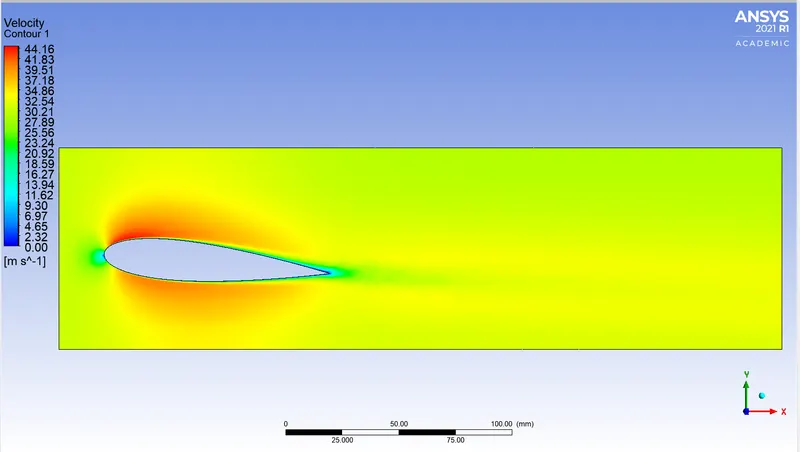
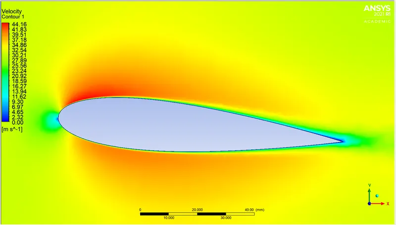
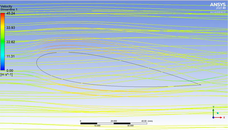
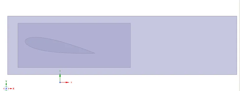
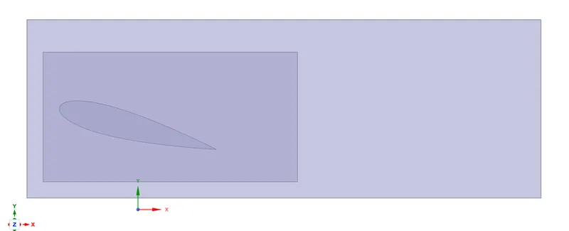
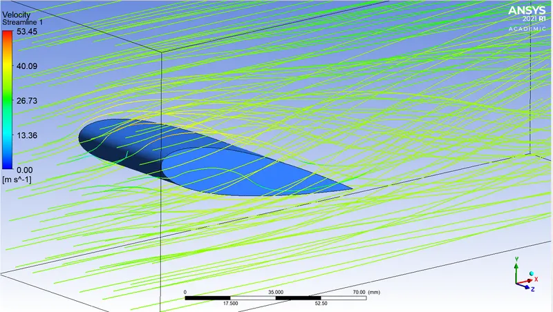
The geometry of the airfoil is downloaded online and loaded in spaceclaim. The enclosures are created around the geometry and then loaded in meshing. Ansys Mesh is used for meshing the geometry. Appropriate named selections are given to the geometry. Initially, a base line mesh is produced which is also used for simulation in Ansys Fluent to have an idea about the contours of various parameters and take a note of the hotspots around the geomtery which would require a refined mesh. After the base line set up is ready with the mesh, it is uploaded in Fluent. The k-omega SST viscous model is used for the simulation with proper boundary conditions. An animation of the velocity contour is also produced along with the coefficient of drag and coefficient of lift plot. 400 iterations will be run with the convergence criteria unchecked. The drag and lift values are noted down after computing it in the console for precision. Now, CFD-Post is booted and the required data is visualised with the aid of contours, vectors, streamlines etc.
Pre-processing and solver setting-
Geometry-
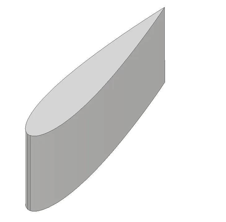
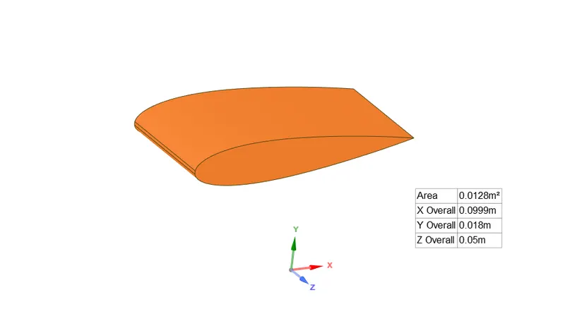
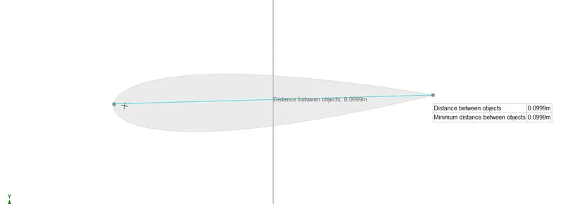
Enclosure for the base line set-up-
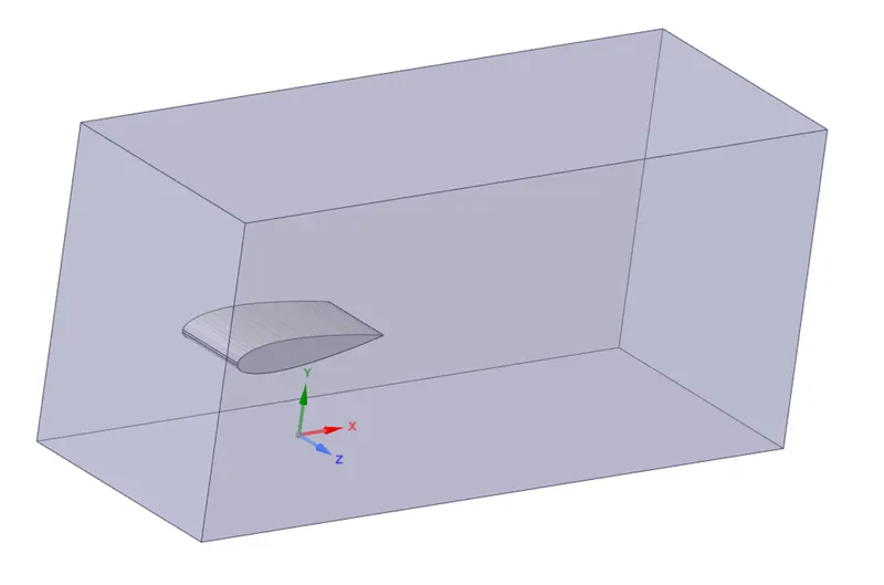
For the base line set-up the angle of attack is set at -2 degrees as this value is the first to start with in this report from where it will be increased up until 16 degrees.
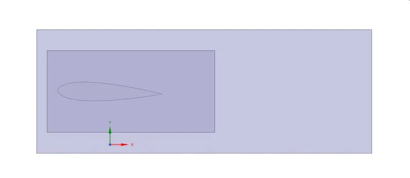
After the enclosure is created around the geometry, the airfoil body is suppressed for physics. This will disallow Ansys Mesh to mesh inside the airfoil body.
Mesh-
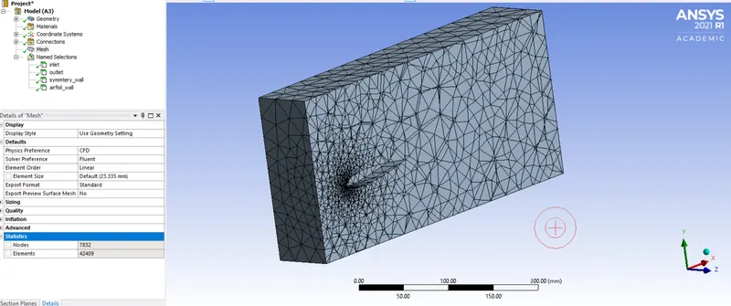
Number of elements = 42409
No mesh refinement efforts were taken and the simulation is performed with this coarse arrangement of mesh.
Fluent-
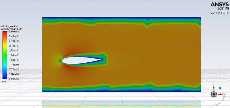
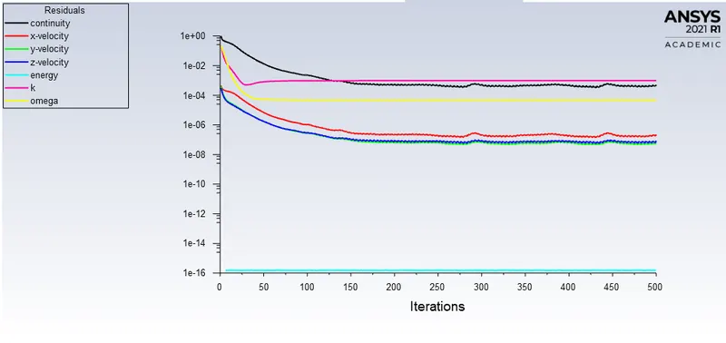
Viscous model - SA model
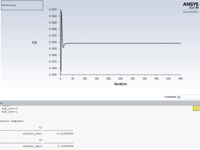
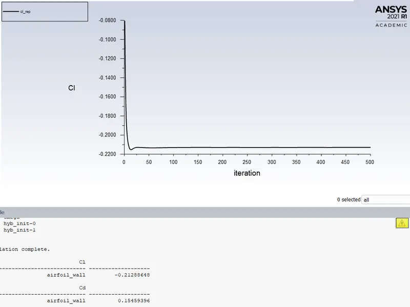
Number of iterations performed = 400 (converged at around 165th iteration)
Coefficient of drag = 0.15459396
Coefficient of lift = -0.21288648
CFD-Post-
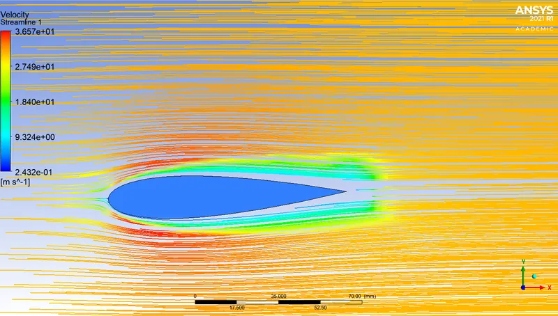
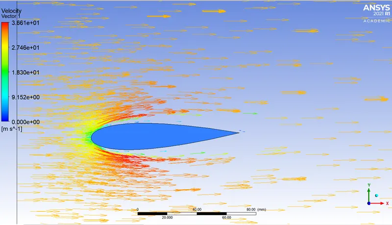
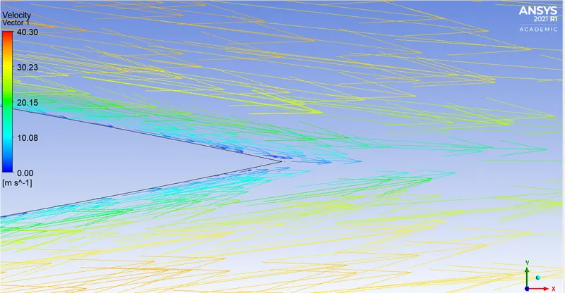
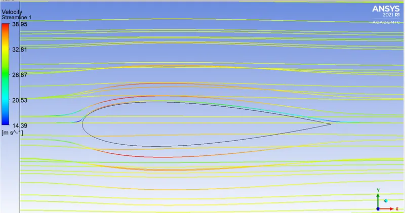
Since the mesh arrangement is coarse the contours generated and the vector plots generated are not reliable for comparing it with any other CFD data, let alone experimental data.
Results-
Now, the further cases will be a series of set-ups with increasing angle of attack on a refined set of mesh.
1. AOA = -2 deg
Geometry-
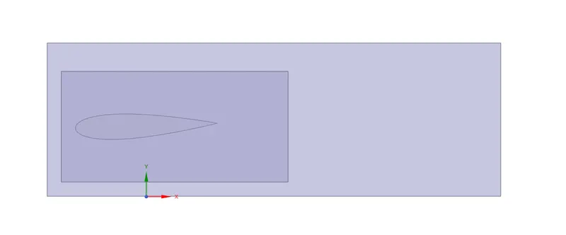
Topology shared and interference terminated.
Mesh-
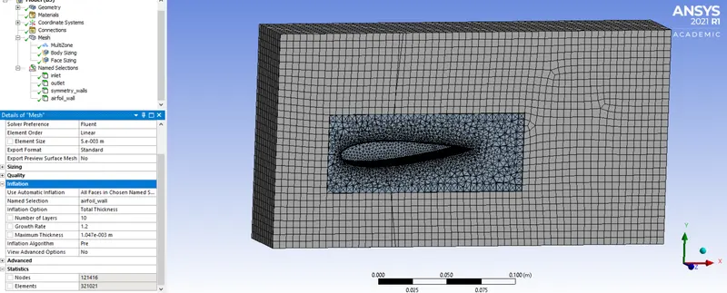
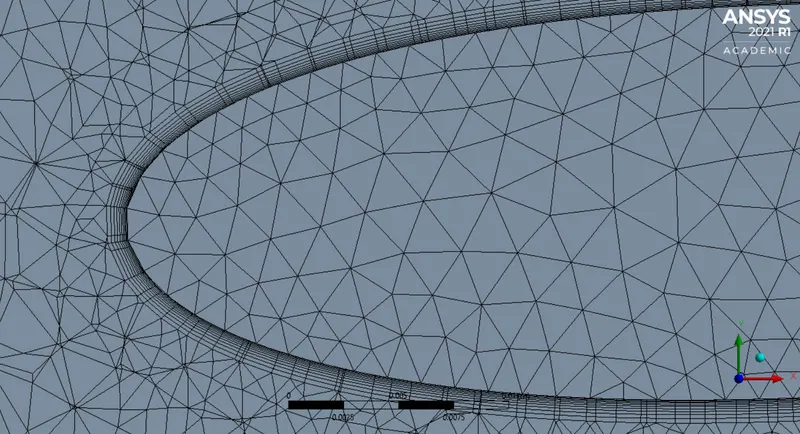
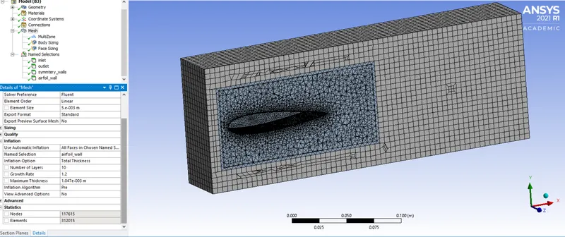
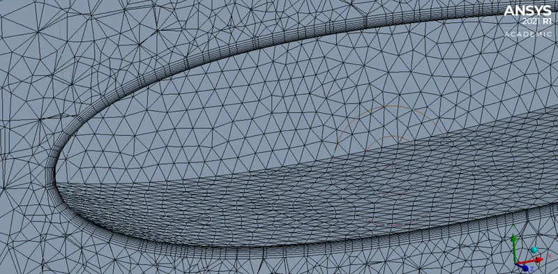
Number of elements = 321021
Element size = 0.005m
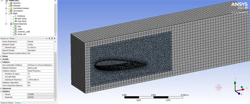
Outer enclosure method applied - Multizone - Hexa(hexa dominant)
Body sizing for inner enclosure = 0.005m (reduced to 0.003m or 0.004m with control over element count)
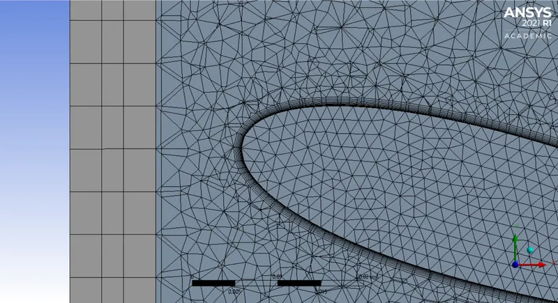
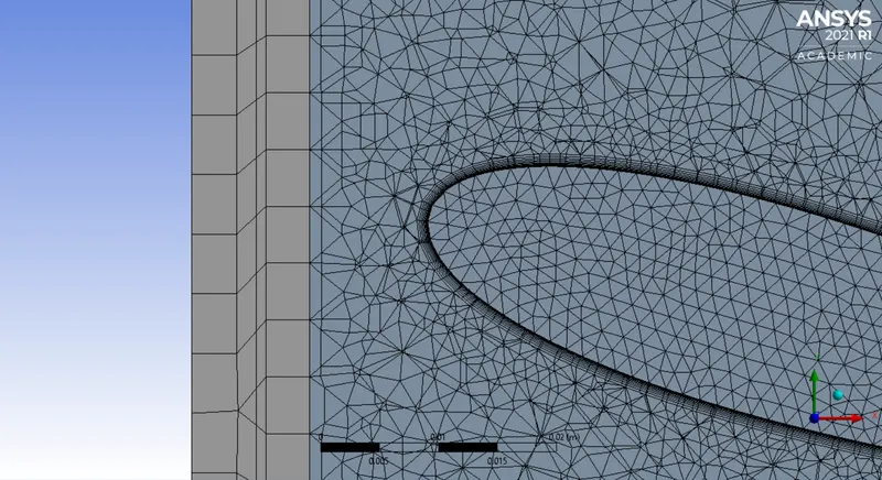
Face sizing for airfoil wall = 0.0015m
Named selections - inlet, outlet, symmetry wall, airfoil walls.
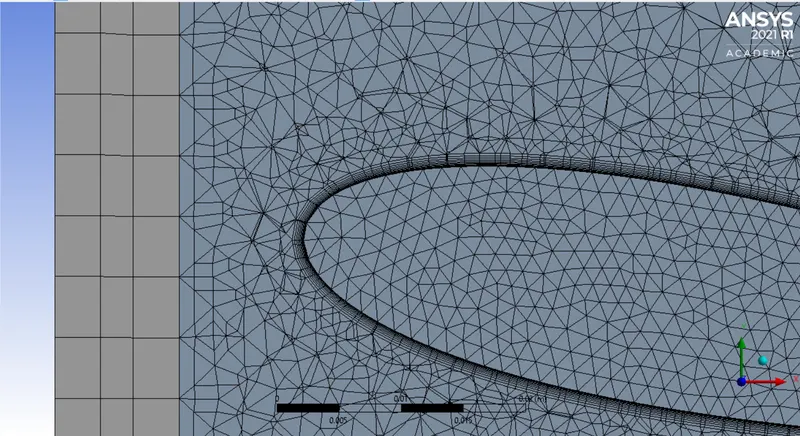
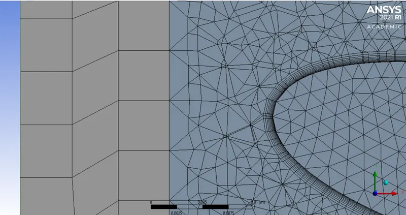
Inflation layers applied to airfoil wall across all cases -
- Total thickness of layer method
- Total thickness = 0.001047m
- Growth rate = 1.2
- Number of inflation layers = 10
Y-plus calculation for inflation layers across all layers -
Velocity, u = 30.48 m/s
Density, ρ = 1.225 kg/m^3
Dynamic viscosity, μ = 0.000017894 kg/m.s
Length (total length in x-direction) = 0.0999m
Y-plus = 4 (assumed between 0 to 5 for k-omega SST model)
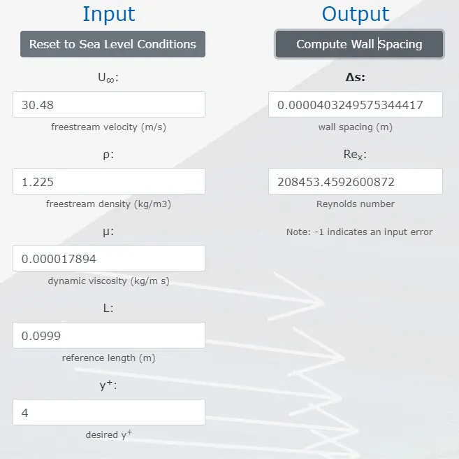
For first layer thickness of 0.000040325m and growth rate of 1.2, the total thickness of the entire layer with 10 inflation layers will be 0.001047m.
Fluent-
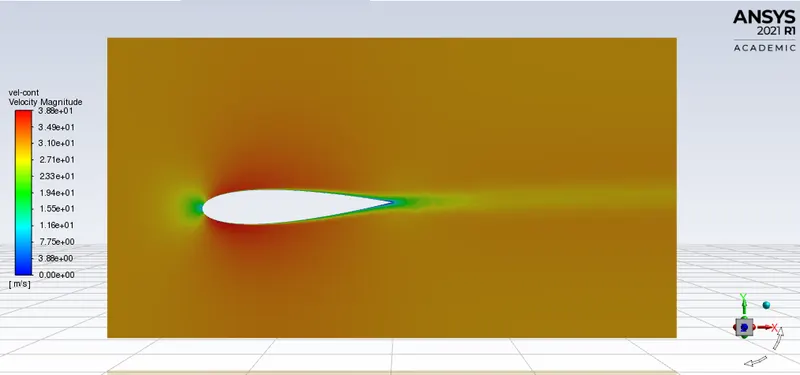
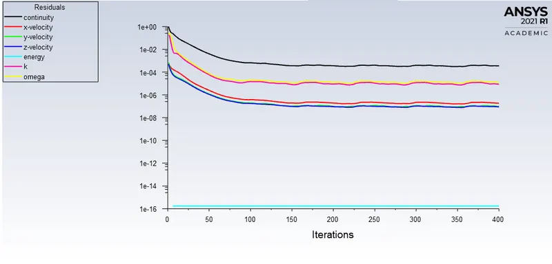
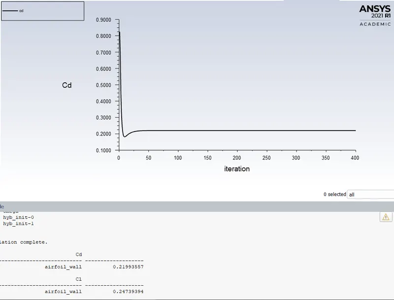
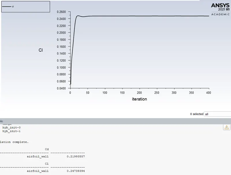
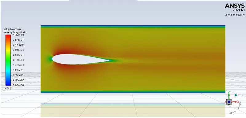
Number of iterations = 400 (solution converged at 160th)
CFD-Post-
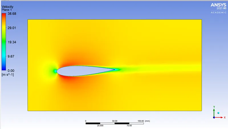
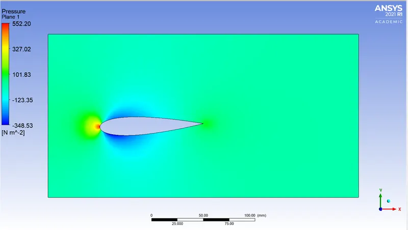
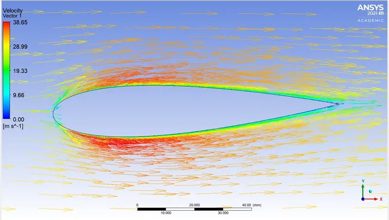
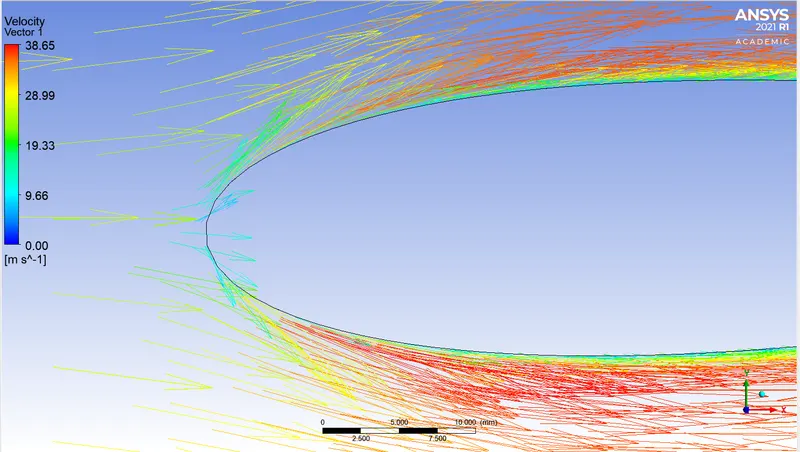
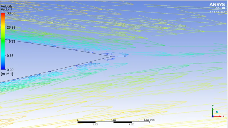
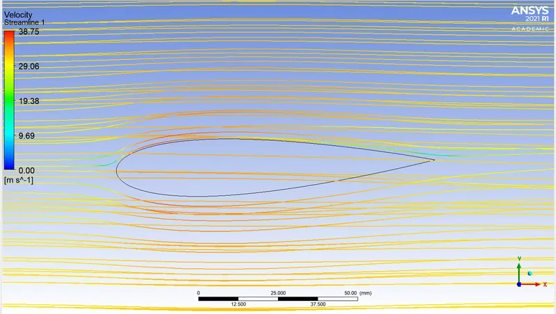
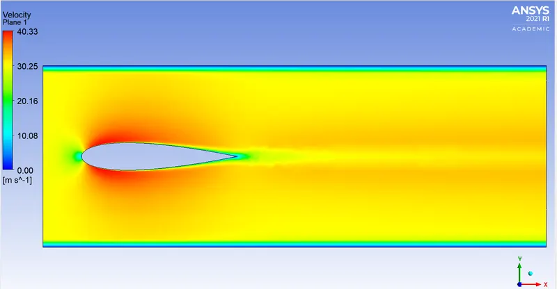
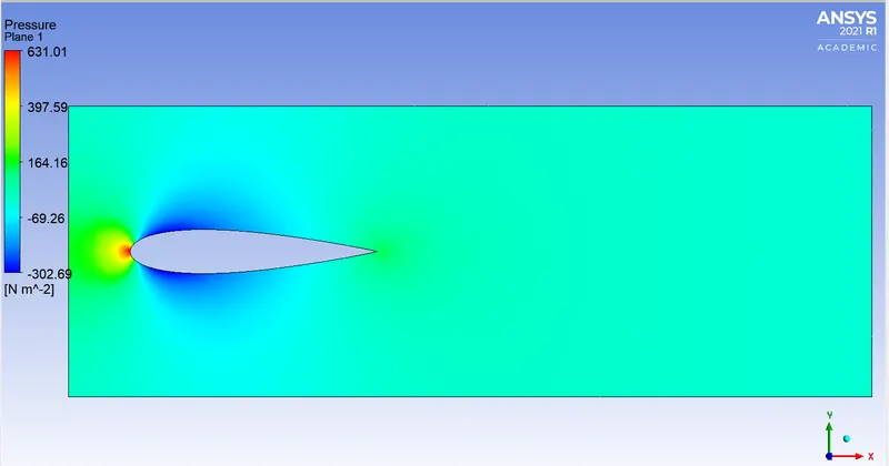
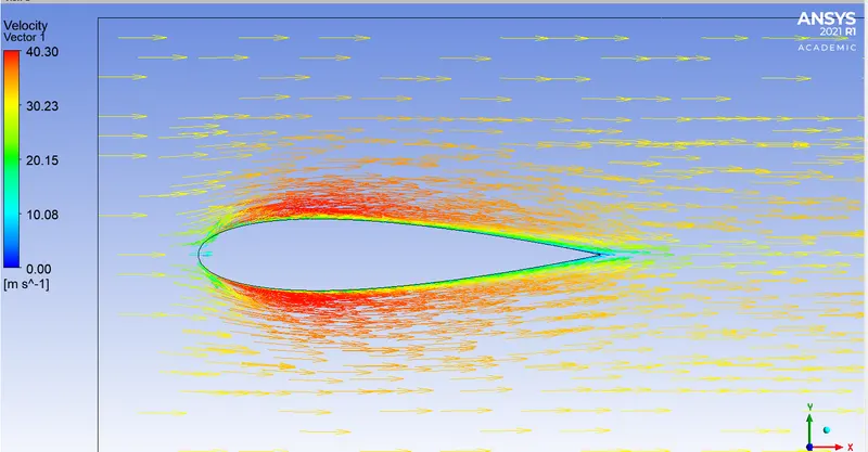
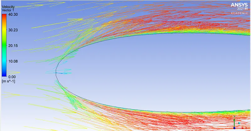
2. AOA = 0 deg
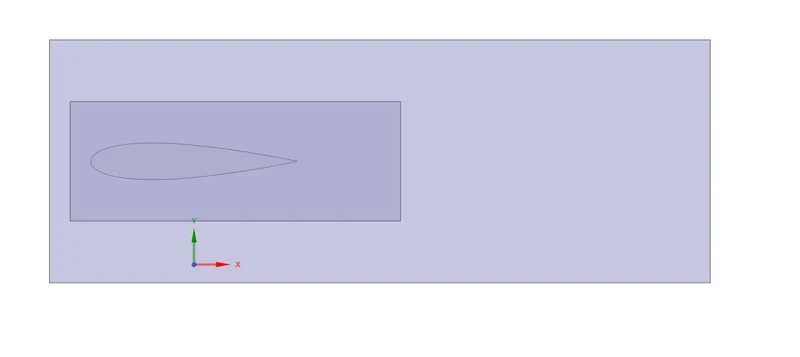
Geometry-
Mesh-
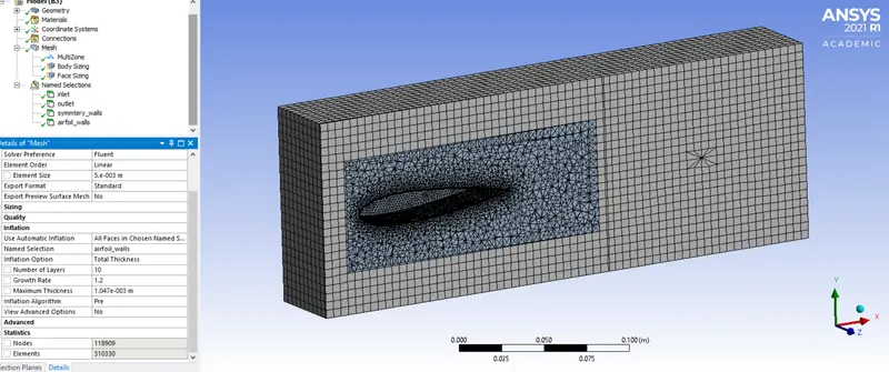
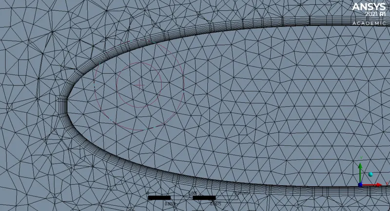
Number of elements = 310330
Fluent-
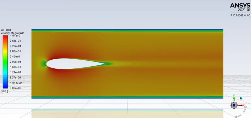
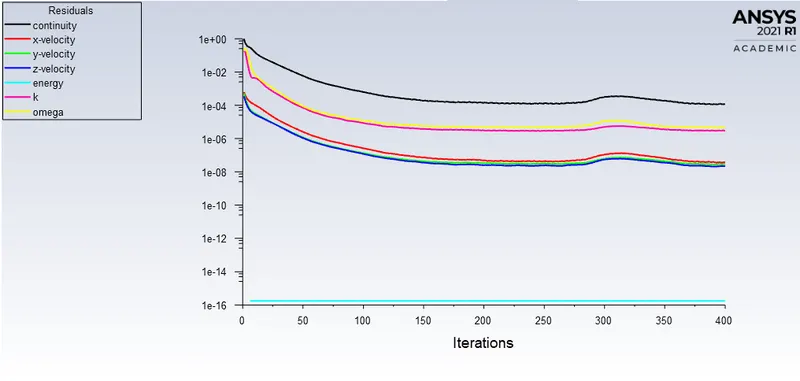
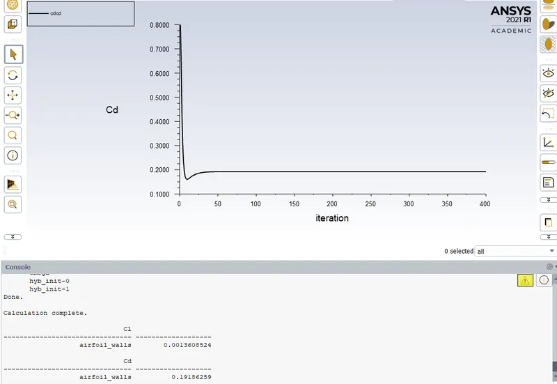

Solution converged at around 180th iteration
CFD-Post-
3. AOA = 2deg
Geometry-
Mesh-
Fluent-
CFD-Post -
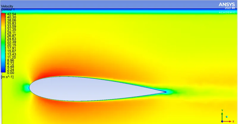
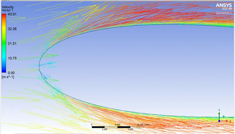
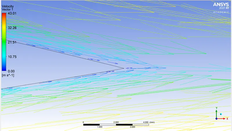
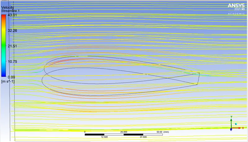
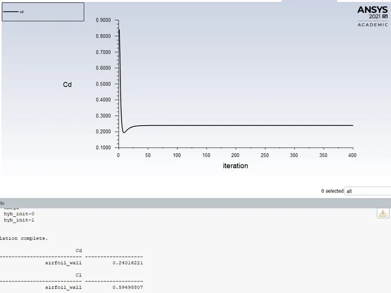
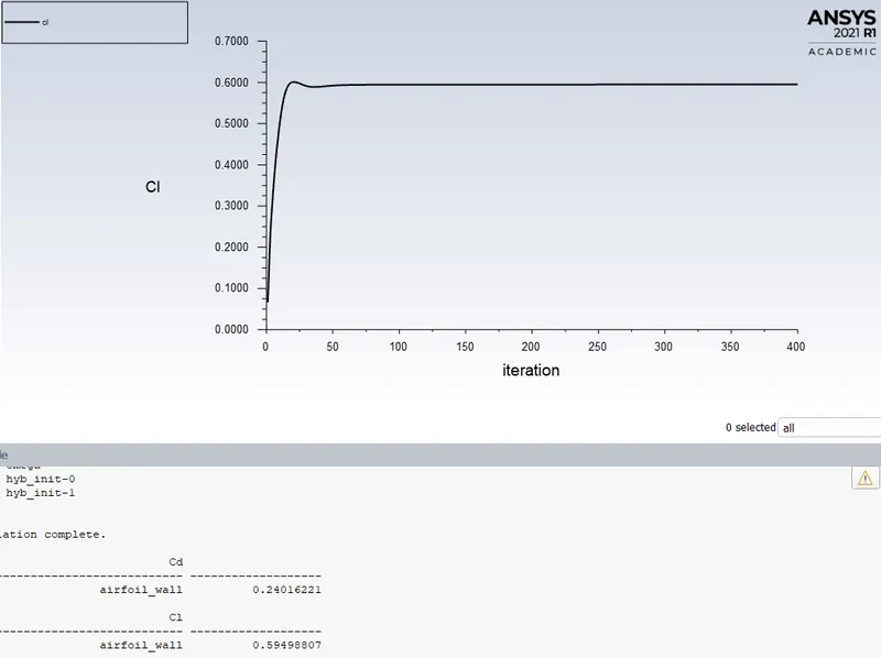
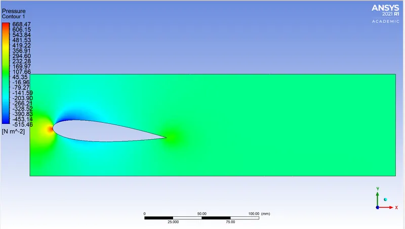
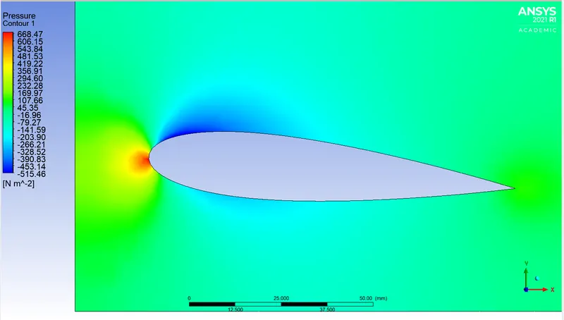
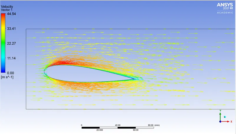
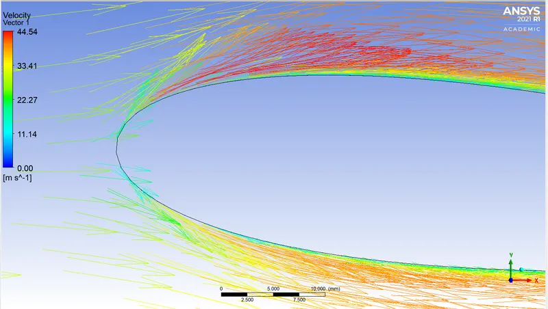
4. AOA = 5 deg
Geometry -
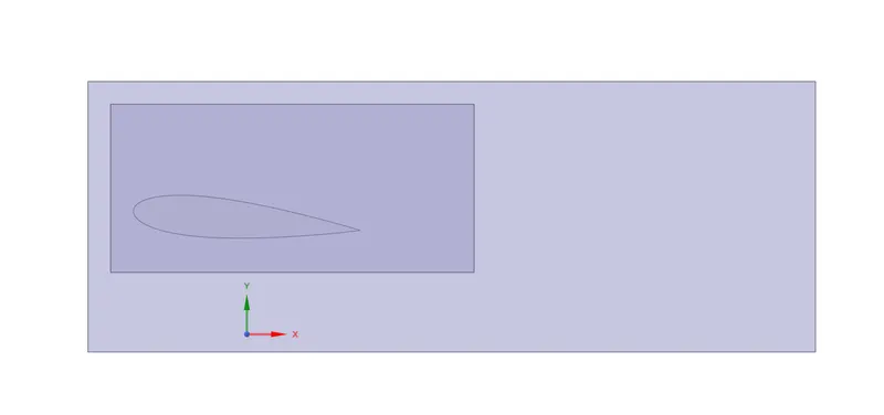
Mesh -
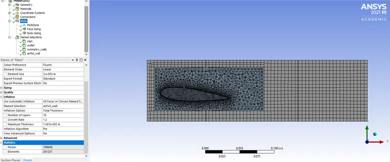
Number of elements = 291237
Fluent-
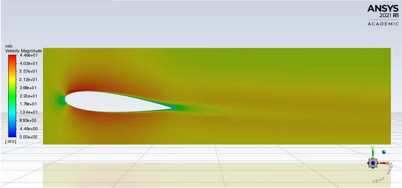
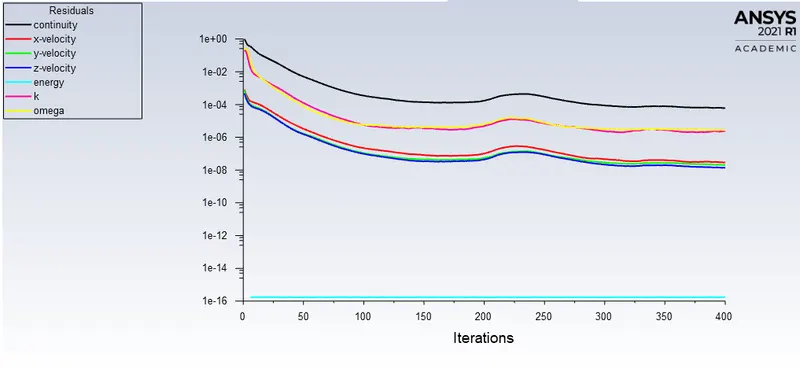
Solution converged at 325th iteration.
CFD-Post -
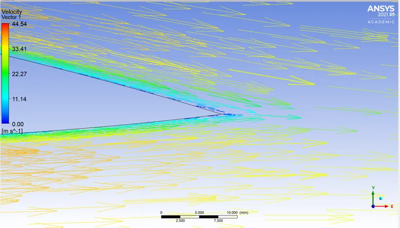
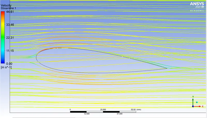
5. AOA = 8 deg
Geometry -
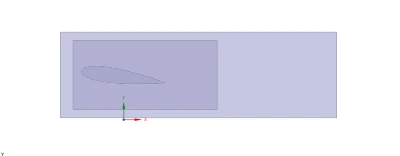
Mesh -
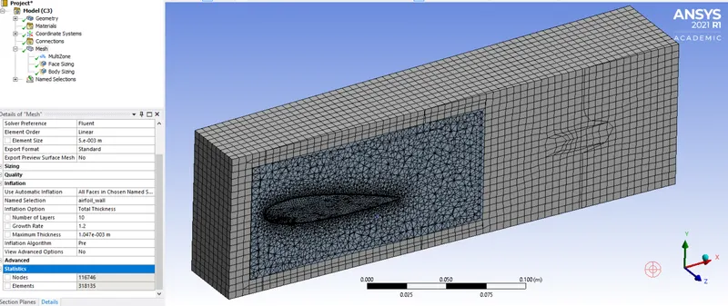
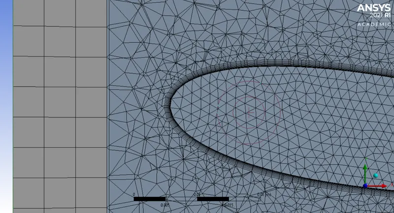
Number of elements = 318135
Fluent -
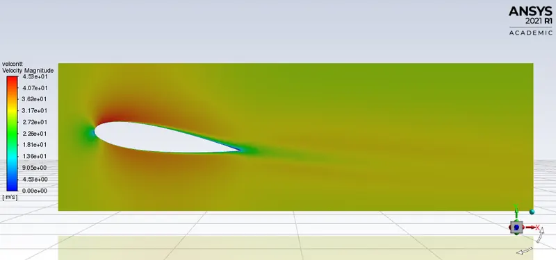
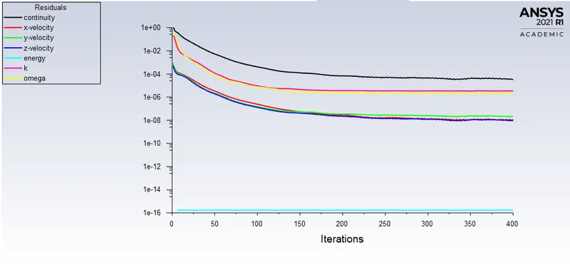
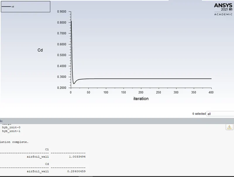
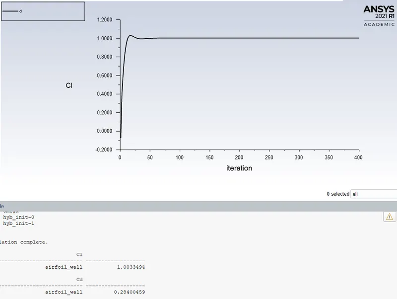
Solution converged at 250th iteration
CFD-Post -
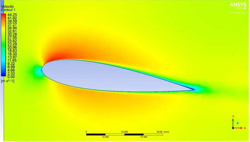
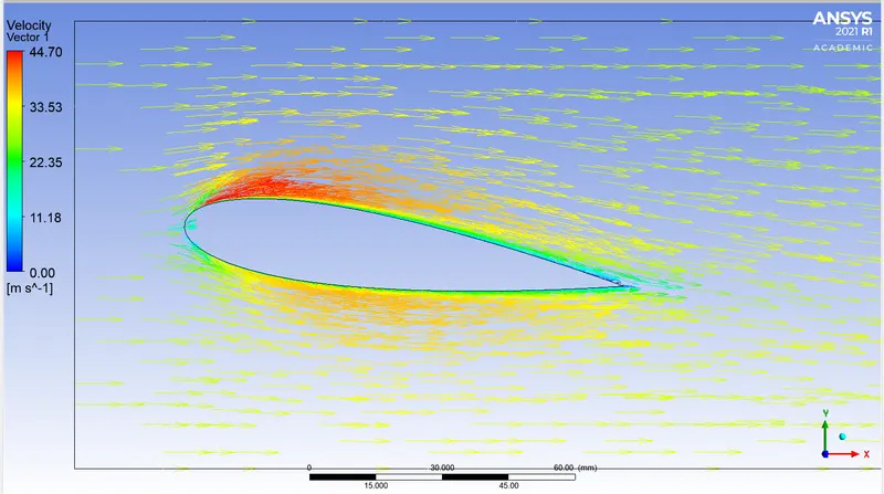
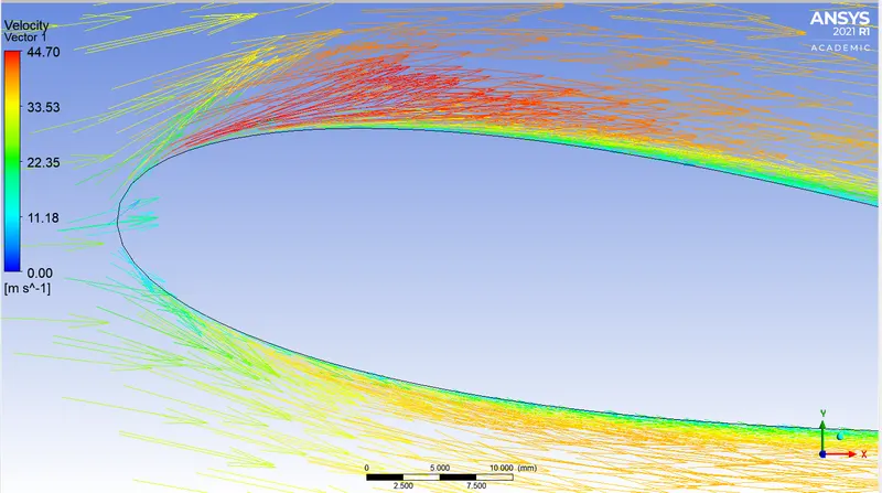
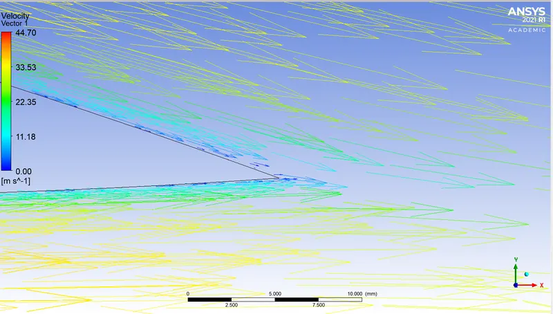
6. AOA = 10 deg
Geometry -
Mesh -
Fluent -
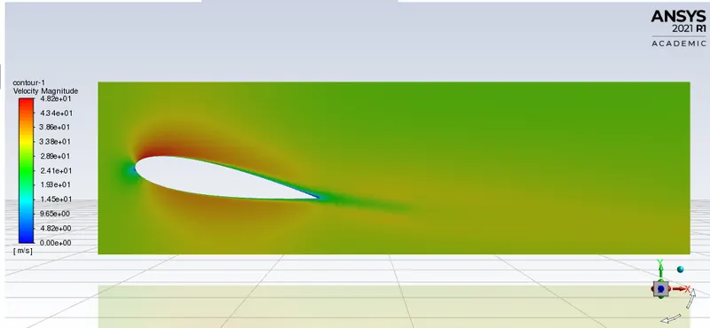
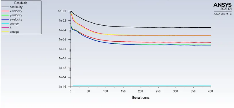
Solution converged at 150th iteration
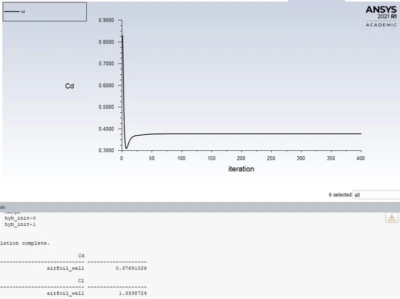
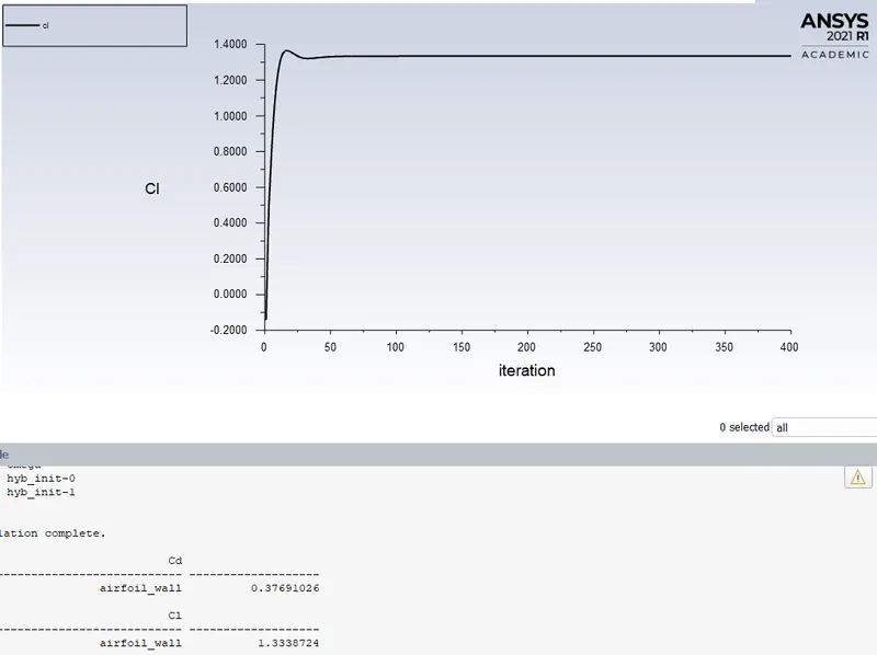
CFD-Post -
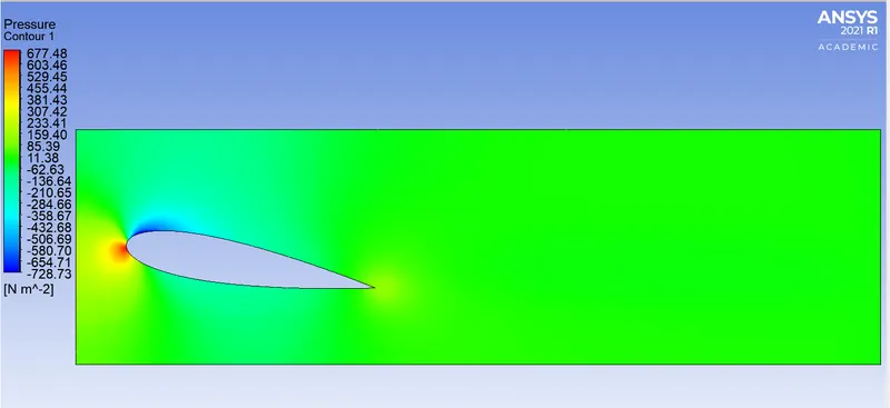
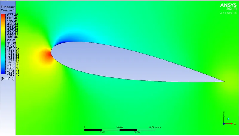
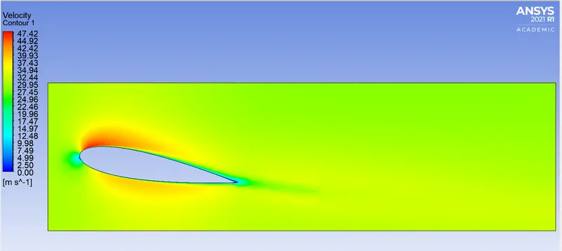
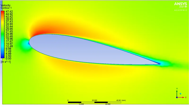

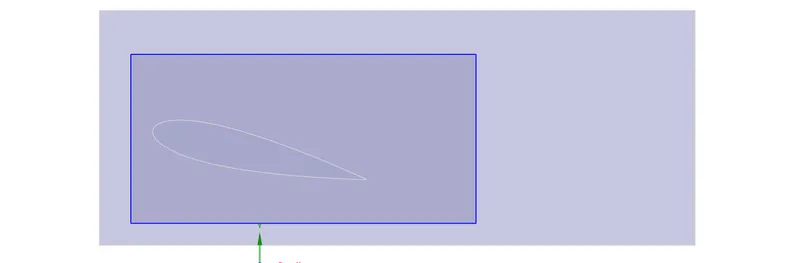
7. AOA = 13 deg
Geometry -
Mesh -
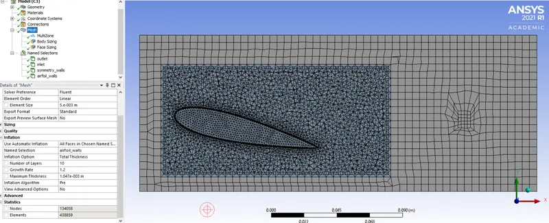
Number of elements = 438859
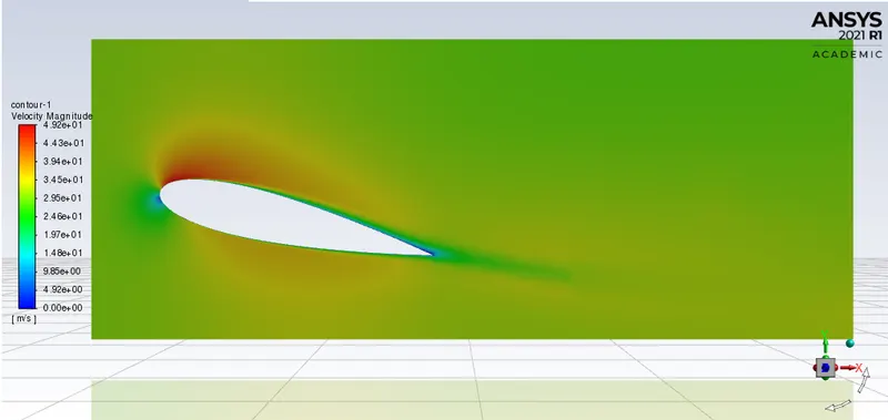
Fluent -
 r
r
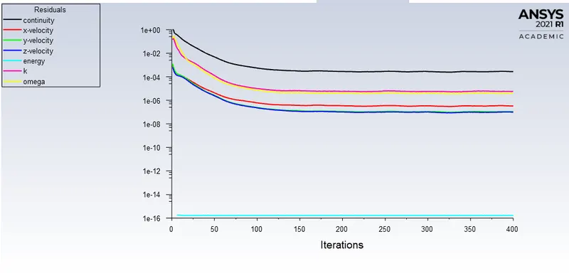
Solution converged at 160th iteration.
CFD-Post -
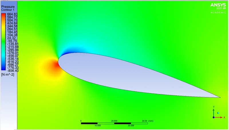
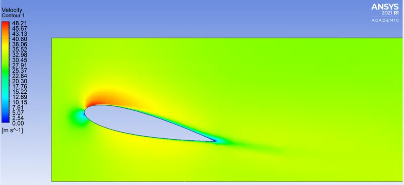
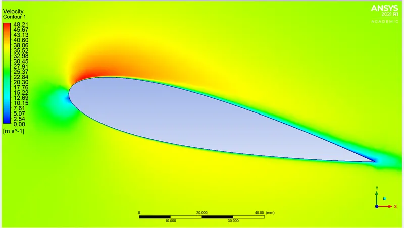
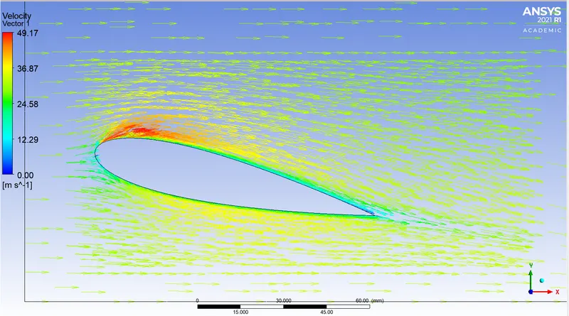
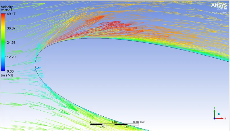
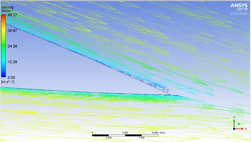
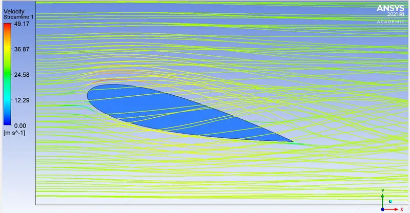
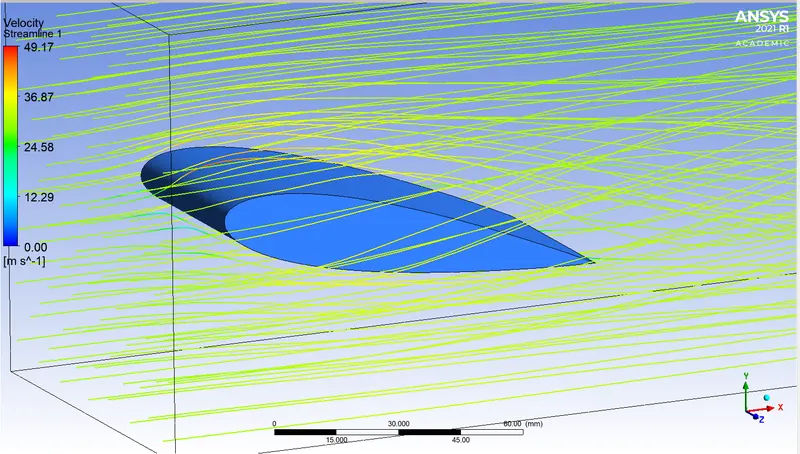
8. AOA = 15 deg
Geometry -
Mesh -
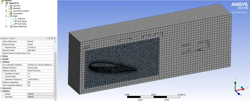
Number of elements = 450593
Fluent -
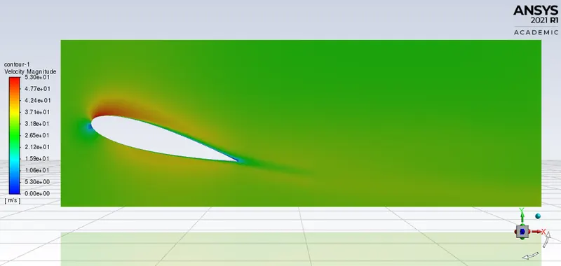
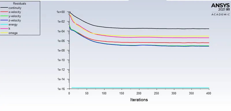
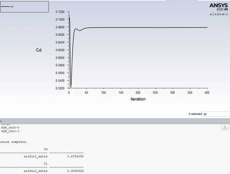
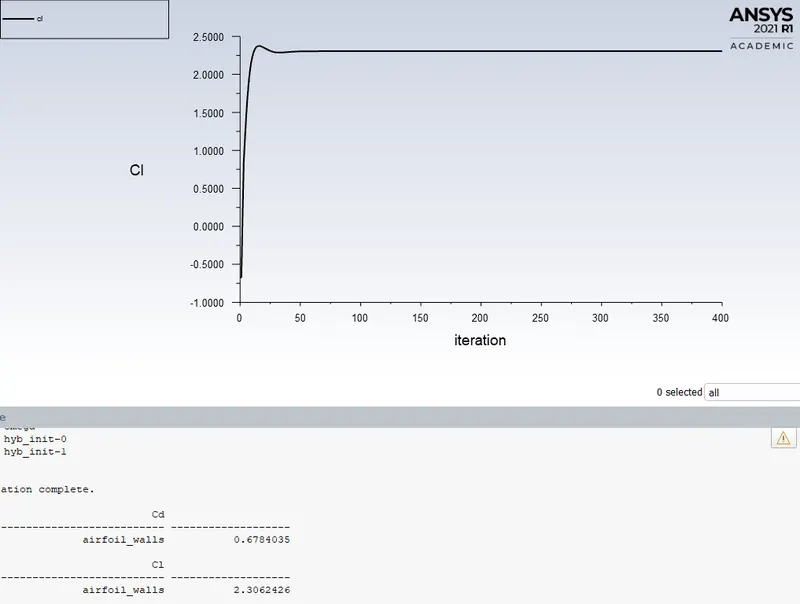
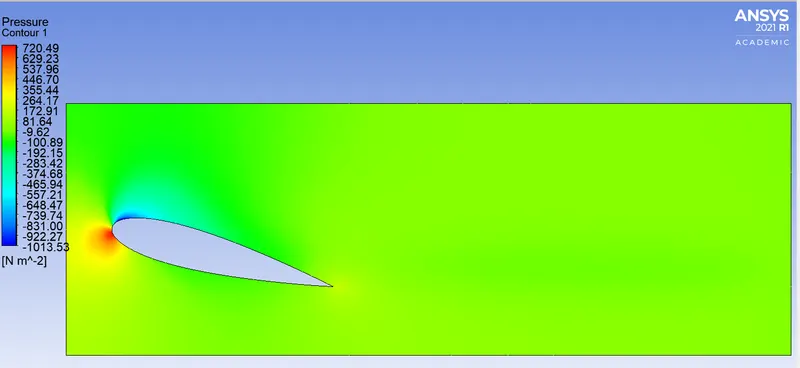
Solution converged at 160th iteration.
CFD-Post -
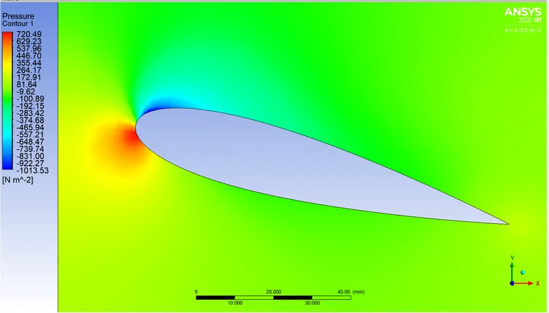
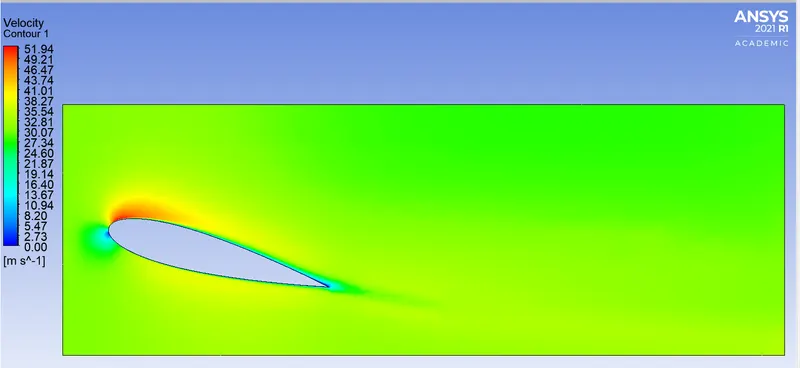
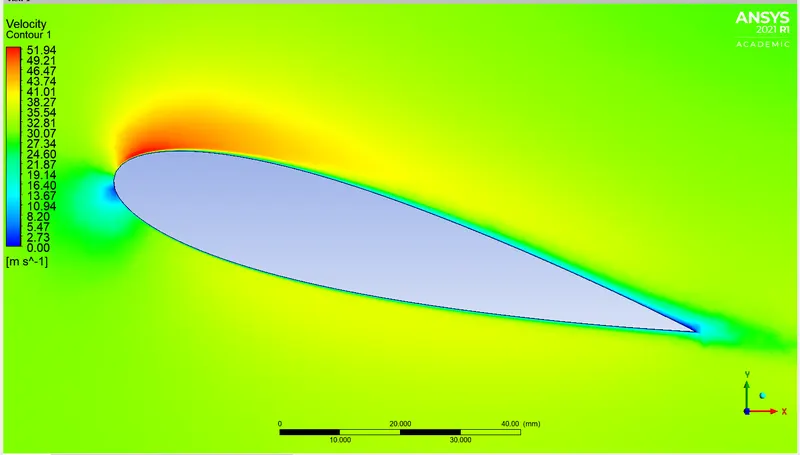
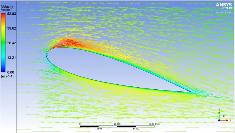
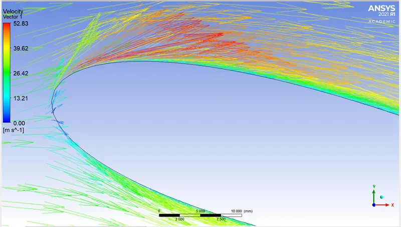
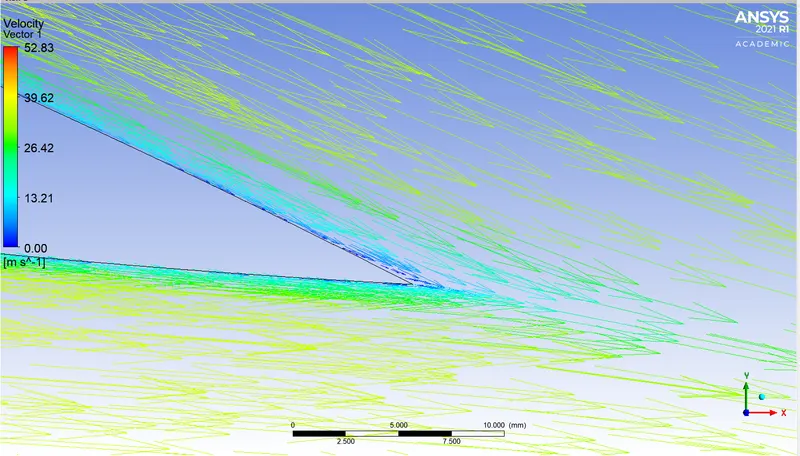
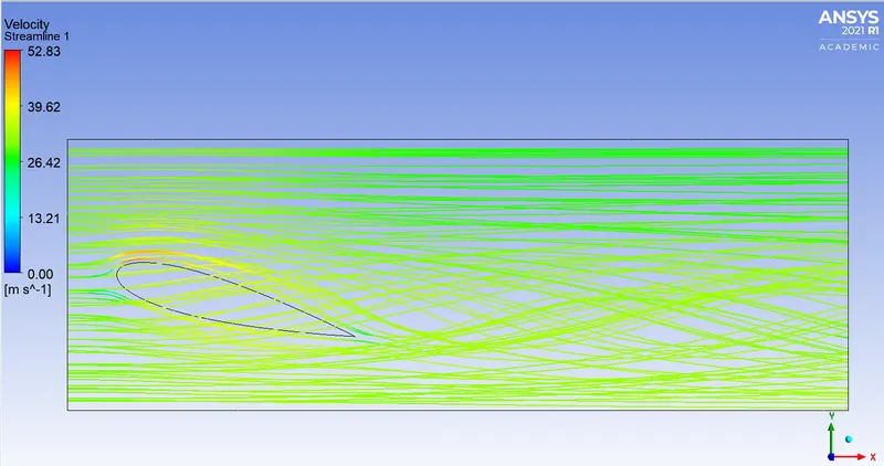
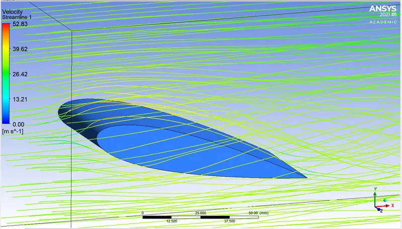
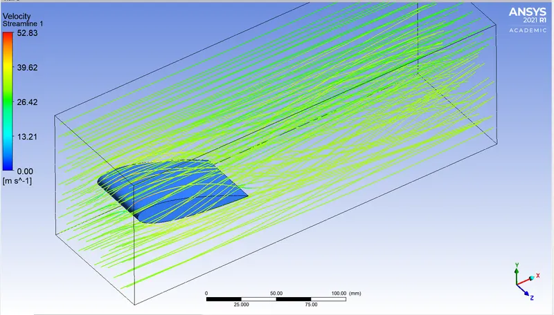
9. AOA = 16 deg
Geometry -
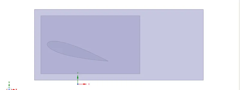
Mesh -
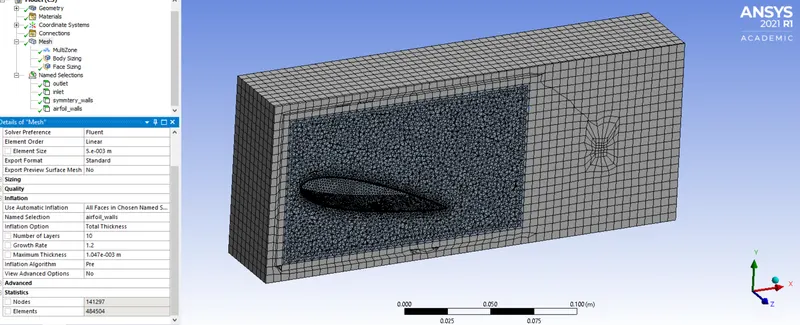
Number of elements = 484504
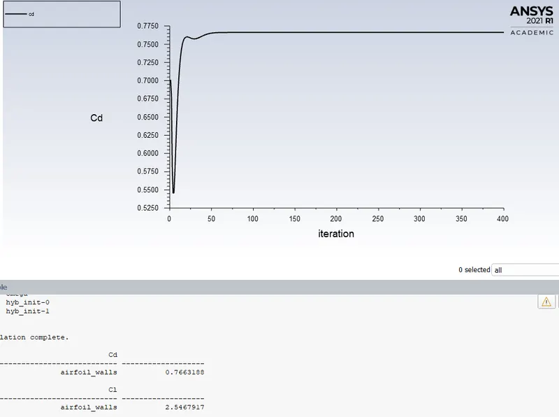
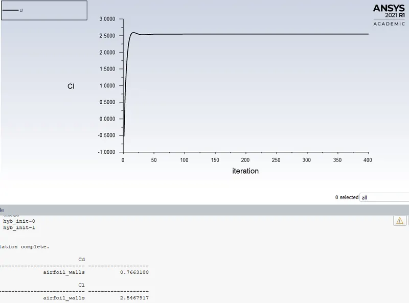
Fluent -
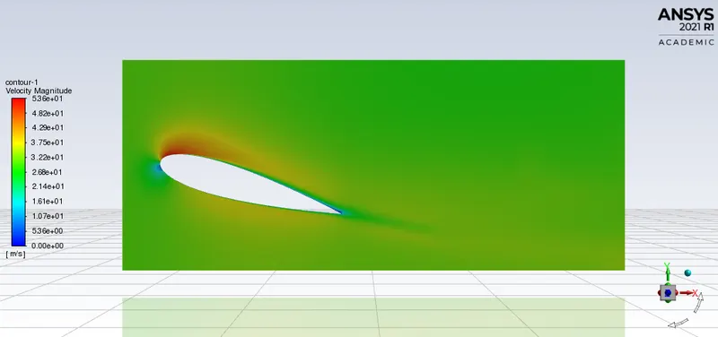
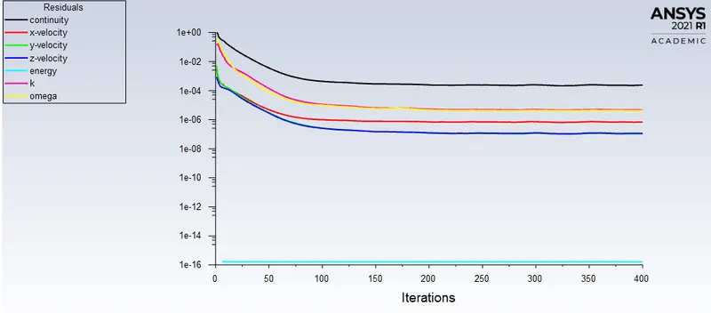
Solution converged at 150th iteration.
CFD-Post -
Conclusion-
Table for values of Coefficient of lift and drag obtained through CFD.
| Angle of attack | Coefficient of lift | Coeffcient of drag |
| -2 | -0.23350 | 0.15536 |
| 0 | 0.00136 | 0.19186 |
| 2 | 0.24739 | 0.21993 |
| 5 | 0.59498 | 0.24016 |
| 8 | 1.00335 | 0.28400 |
| 10 | 1.33387 | 0.37691 |
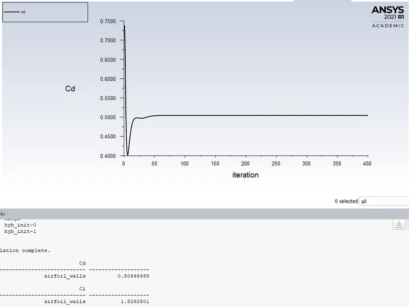
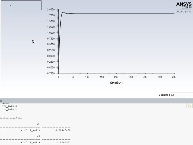
| 13 | 1.82925 | 0.50446 |
| 15 | 2.30624 | 0.67840 |
| 16 | 2.54679 | 0.76632 |
Table of comparison between coefficient of lift obtained experimentally and through CFD.
| Angle of attack | CFD values | Experimental values |
| -2 | -0.23350 | -0.0939 |
| 0 | 0.00136 | 0 |
| 2 | 0.24739 | 0.175 |
| 5 | 0.59498 | 0.2532 |
| 8 | 1.00335 | 0.4 |
| 10 | 1.33387 | 0.5353 |
| 13 | 1.82925 | 0.6784 |
| 15 | 2.30624 | 0.8924 |
| 16 | 2.54679 | 0.8491 |
(Experimental values are obtained from an online paper, included at the end of this report as a reference)
- From the data in the table we can conclude that the CFD values of the coefficient of lift shows promising, consistent results.
- Due to the differences in the scale of the airfoil body used in the wind tunnel and the one drafted for the simulation there is a significant difference in the CFD and the experimental values.
- For -2, 0, 2 and 5 degrees the values are not far from each other in comparison of the two different methods.
- The coefficient of lift is gradually increasing with the increase in the angle of attack. The increase in angle from 0 degree to 16 degrees increases the coefficient of lift significantly from 0.00136 to 2.54679.
- Since, we know that the aerodynamic force is the resultant force of lift and drag forces, the higher lift and drag coefficients suggest higher aerodynamic forces acting on the body with higher angle of attack.
- The lift coefficient is close to being zero for angle of attack equal to zero.
- A gradual increase in the angle of attack will help increase the lift force acting on the body, which is the same approach adopted for airplane flights while taking off.