Identification of Cracks
Identification of Cracks
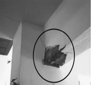
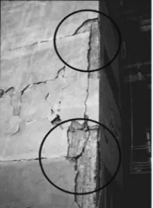
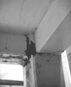
Q.1.What is the mode of failure or damage of the beams in the figure? Would you characterize the case as damage or as a failure? Are the damages repairable? Elaborate.
a)
Ans=
The above figure represents the Flexural cracks developed at the bottom flange of the beam.
- Failure, with concrete crushing and bar buckling at bottom flange next to the column Flexural damage is mostly associated with cracking and spalling of concrete and yielding of the reinforcement. By contrast, flexural failure comes with disintegration of concrete beyond the cover, often with buckling (or even rupture) of bars. Such effects, shown in figure above, happen only at the bottom flange of a beam, because the slab provides the top flange with abundant cross-sectional areas of concrete and steel reinforcement. The vertical crack at the face of the support, across the full depth of the beam, tends to remain open and increase in width for each cycle of deformation; bottom bars may buckle and then rupture under the large cyclic excursions of strain across the open crack.
b)
Ans=
- Pullout of beam bars from narrow corner column, due to short straight anchorage there - Beam bars with insufficient anchorage in a joint may pull out in an earthquake. Such a failure of bond and anchorage shows up at the end section as a crack through the full depth of the beam. A characteristic feature of a pull-out crack is its large width, well in excess of the residual crack width typical of yielding of the steel (which is a fraction of a millimetre or around 1 mm). The impact of this type of bond failure on the global behaviour is not dramatic: the beam cannot develop its full moment resistance at the end section and the force resistance and stiffness of the frame it belongs to drops accordingly. The loss of beam anchorage prevents a proper plastic hinge from forming at the ends of beams. The damage is reparable, although the original deficiency, namely the poor anchorage of beam bars in the joint, cannot be corrected easily.
- These type of failures are non-repairable.
c)
Ans=
This figure represents Beam-Column connection failure. It occurs due to the formation of plastic hinge at undesirable locations. These beam column juctions are the weakest links as it fails in shear under lateral seismic loads resulting in unrepairable damage to the buildings. Shear failure governs in beam column connection failure. The shear cracks thus developed, if left unattended can lead to collapse of the building and can cause severe damage to the structure.
The plastic hinge formation at the beam column interface is undesirable which leads to shear cracks, instead the plastic hinge should be formed some distance away from the junction.
This failure can also occur due to inappropriate detailing.
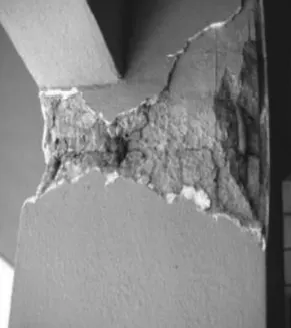
Q.2.What is the mode of failure or damage of the beams in the figure? Would you characterize the case as damage or as a failure? Are the damages repairable? Elaborate.
a)
Ans=
The failure shown in this figure is the Compression failure. This figure shows the concrete crushing.
Compression failure is caused due to excess axial stress. Due to this concrete and steel will reach the yield stress. As a result the concrete crushes and the steel buckles.
This type of failure is non-repairable.
b)
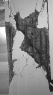
Ans=
This figure depicts the Confinement failure of column.
This failure is mainly caused due to inappropriate detailing of plastic hinge location. Shear force increases during an earthquake especially at columns and beam-column joints.Seismic design requires increasing of ductility of structures for performance-based design approach. In particular, columns of buildings can be having sufficient transverse reinforcement in the plastic hinge region. Therefore, structural elements which have such details show low performance against dynamic loading and loose their shear and axial load carrying capacity.
These failure are also irrepairable.
c)
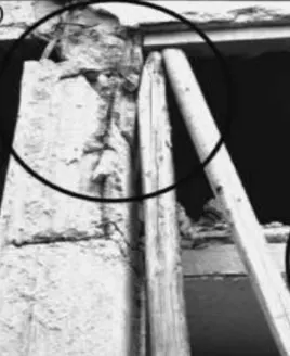
Ans=
The failure depicted in this figure is the Short column failure or Influence of partial height infill increasing column shear force.
This type of failure can be caused due to structural adjustments or due to continous openings at the top of infill walls between columns. Lateral forces that occured by an earthquake are carried by column and shear walls. Length of columns is an important factor for dissipation of these loads. When the length of column decreases, the column becomes stiffer and brittle than other columns and this columns attracts more shear forces. Thus shear failure which is the critical type of concrete column damage occurs at these columns.
This failure is also non-repairable.