Hood design-Week 2
1. AIM :
HOOD DESIGN AND DEVELOPMENT
2. OBJECTIVE :
- Design Hood outer panel, Inner panel and the necessary reinforcements by following the Master section mentioned with the design parameter.
- Submit an assembly of Hood inner panel, outer panel, latch, hinge and the reinforcements.
3. BODY OF THE CONTENT :
The Hood is an opening body panel that covers the engine in a front-engine vehicle. The hood is also considered as another type of door in a vehicle as it consists of an outer panel and inner panel. The inner panel provides strength while the outer panel functions as the metal cover. In design perspective hood should meet some specific conditions like Pedestrian safety, Hood head zone for the lock striker, force distribution when subjected to frontal collision (occupant safety), manufacturability etc.
A typical hood assembly consist of hood outer panel, inner panel, striker, hinge, hood stay. Hood stay is an apparatus for supporting the engine hood of a vehicle in its open position. Common types of hood stays are Support Rod and Gas Stay. Support rods are manually operated and they are cost effective and simple to design whereas gas stays require no man power but they are costly. Hood are typically made out of the same material as the rest of the bodywork. Deep drawing, hemming, blanking and piercing are the common sheet metal operations that are used in manufacturing hoods in automotive industries.
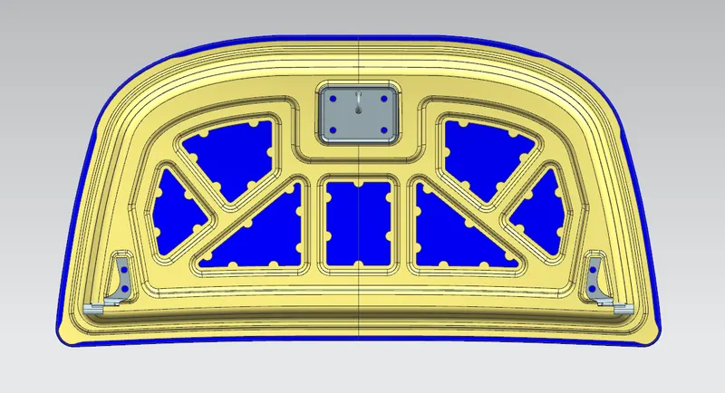
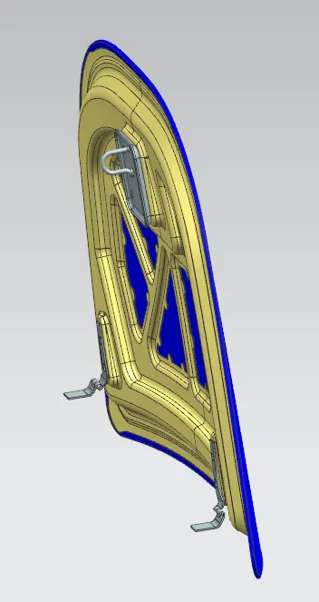
Components
1. Hood outer panel
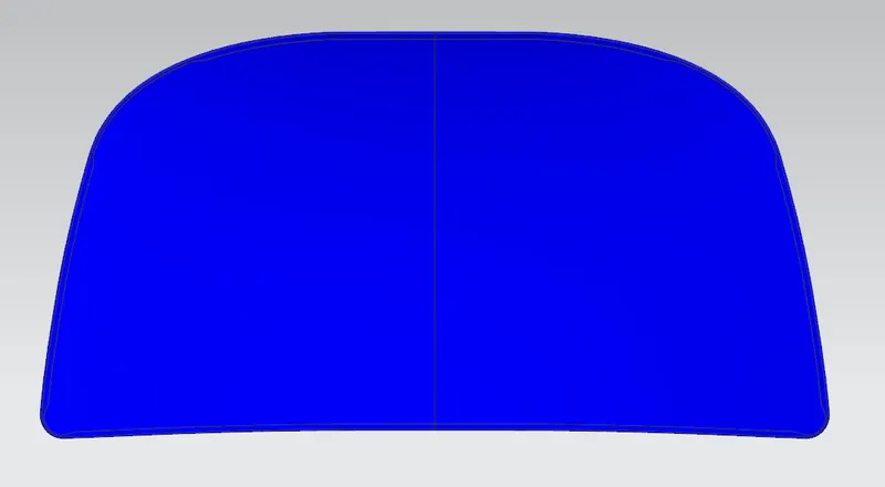
Outer panels are the aesthetic elements of a car. It is the styling team who provides the skin for the outer panel. The shape, position and size of the hood should satisfy the safety norms. So while designing the hood we should give more importance to pedestrian safety. The outer panel is attached to the inner panel by hemming. So, it is necessary to provide required hemming flange and reliefs for the hemming operation. We also provide mastic sealants between outer panel and inner panel to reduce vibration.
2. Hood inner panel
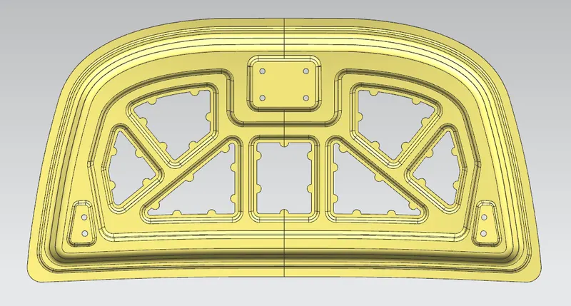
Inner panel is the part that gives strength and rigidity to the outer panel. The master section represents the initial emboss shape and size. Then we provide the emboss for the lateh and hinge elements after fixing the location.
3. Reinforcement
Reinforcements are provided according to the design requirements. Mainly it is provided at the hinge and latch regions to improve the strength locally. Usually thickness of reinforcements will be higher than that of the inner panels and the value varies according to cost and requirement. According to the design requirement here it is given 1.5mm thickness to both hinge and latch reinforcements.
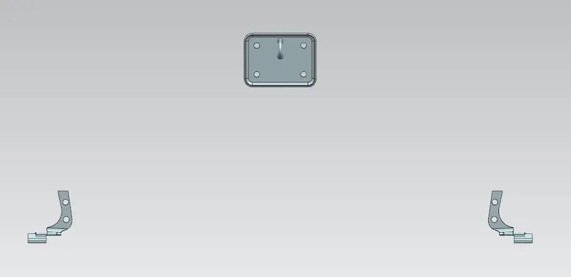
4. Latch and Striker reinforcement
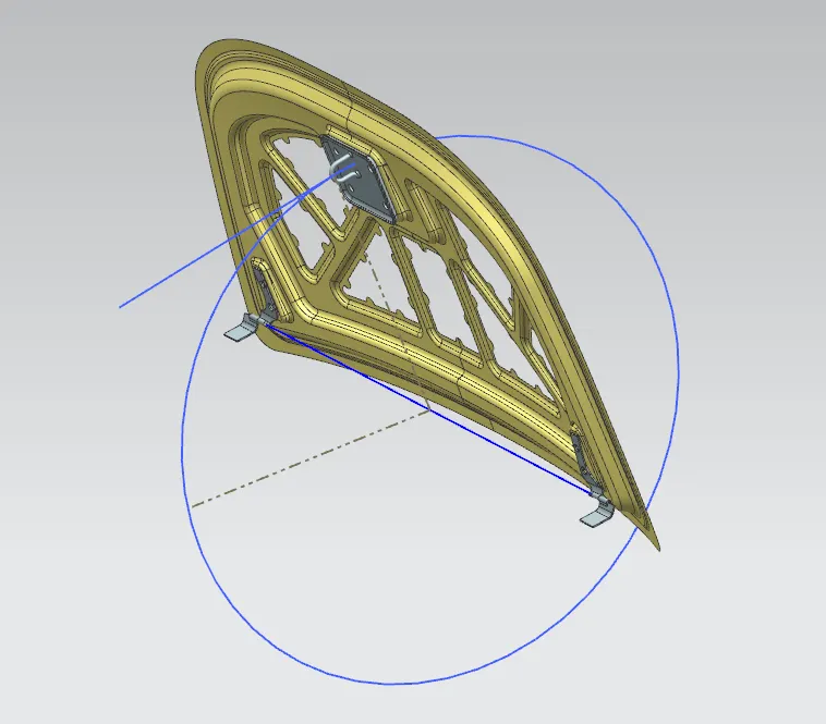
Latch trajectory is given by the circle drawn from the hinge axis point. Hinge axis point is the centre point of the hinge axis. First, we can fix either the latch or the hinge. If we have fixed the hinge position then we should plot the Trajectory circle for the latch. For proper mating condition the striker axis through the tip of the striker should be tangential to the latch trajectory.
Materials
Hoods are typically made of the same material as the rest of the bodywork. This may include steel, aluminum, fiberglass or carbon fiber. However, some aftermarket companies produce replacements for steel hoods in fiberglass or carbon fiber to make the vehicle lighter. Before designing, let understand the rules and regulation standards for designing the hood.
- A perfect hood design means it should have a great impact distribution angled outside the car.
- In Japan and Europe, regulations have come into effect that places a limit on the severity of pedestrian head injury when struck by a motor vehicle. This is leading to more advanced hood designs, as evidenced by multicore hood inner panel designs.
- European Enhanced Vehicle-Safety Committee (EEVC), European New Car Assessment Program (euro NCAP)
Functional and Safety Requirements
- The most important safety requirement to be considered while designing the Hood is the frontal collision requirements. The design intention of the hood according to the frontal collision requirement is that the hood crushes and dissipates forces in the upward direction and to the hard points on the hood thereby deflecting the force on to the body and not the passengers.
- The second major function of the hood is the opening and closing of the hood. This is done with the help of the lateh and striker. To position the latch and striker effectively, we first position the hinge and draw the hinge axis. Now, using the hinge axis from the centre we draw a big circle to the position there we need to place the latch.
1. Pedestrian- Vehicle Collision
When a car crashes on the pedestrian, the whole human body wraps around the front shape of the car and the head impacts on the bonnet or the windscreen. The distance on which the head impacts on the car from the ground is called as the Wrap Around Distance (WAD). To be specific the Wrap Around Distance is a measurement of distance from the ground to the head impact zone over the outer surface of the car. The wrap around distance is measured longitudinally in the center of the vehicle from the ground. 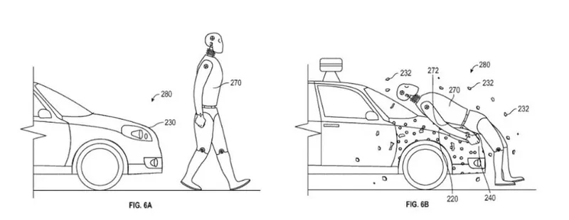
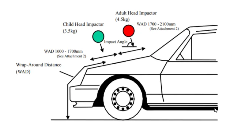 The severity of the injury caused by the frontal crash depends on the type and shape of the vehicle, speed of the vehicle and the movement of the pedestrian relative to the vehicle. In addition to these parameters, the wrap around distance plays a major role in the safety measurement of a pedestrian. During the crash analysis, based on the Wrap Around Distance (WAD), two test areas will be created namely Child head impact zone and the Adult head impact zone. The child head impact zone is between 1000 to 1700 mm WAD and the adult head impact zone ranges between 1700 to 2100 mm WAD.
2. Hood head zone for the lock striker
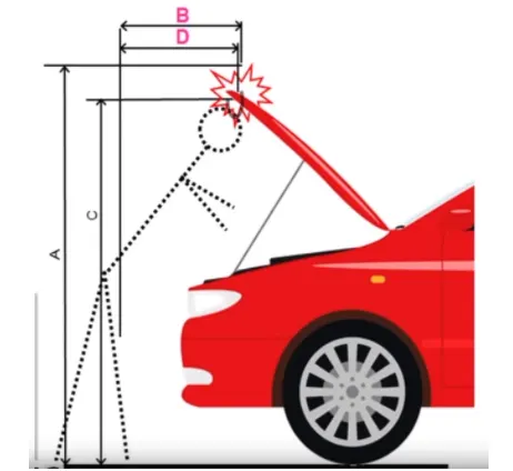
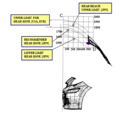
The opening angle of hood will give A, C, B And D with respect to the ground. those A, B, C & D are decided in the head zone. Opening angle varies from region to region depending on average human weight. Depending on the standards we are deciding the angle. so from the angle data, Support rod or Gas stay is designed.
Mastic Data
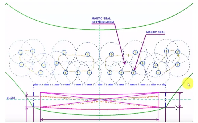
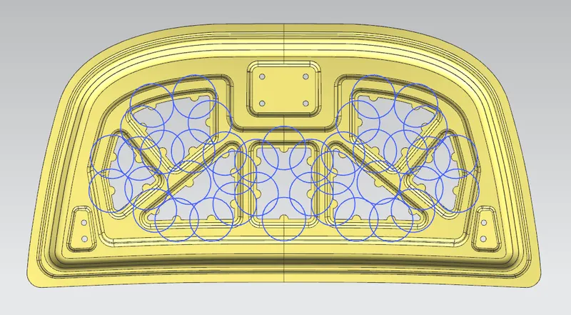
Hood commonly possess large surface area and hemming can only be provided through its boundary. We cannot use other joining techniques like welding, riveting etc because they leave marks on the outer panel which spoil its aesthetic appearance. So, mastic sealants are used to stick the inner surfaces of outer panel and inner panel. Mastic seglants are elastic compound that behave like rubber. It is applied between the inner and outer panels at specified spots. Each spot of mastic sealants has its effect arouiid a circular region of 80mm diameter. Thus, the mastic points are arranged in such a way that it covers the areas away from the hemming which are more vulnerable to vibrate and it reduce noise and harshness.
Deep Drawing
Deep drawing is a common process in industry for manufacturing products from sheet metals. The process is widely used for producing different products such as automotive parts, cans, sinks and housing, and the application areas are getting larger every day. In the deep drawing process, the sheet metal is radially drawn into the die cavity by the mechanical action of a punch. In this process the workpiece is put onto the die and the blank holder is then introduced on the top of the workpiece, which is not deformed by the punch. The role of the blank holder is to control the sliding of the workpiece during the process. After closing the blank holder, the punch moves down and deforms the workpiece to its final shape. The punch possesses the shape of the product to be drawn.
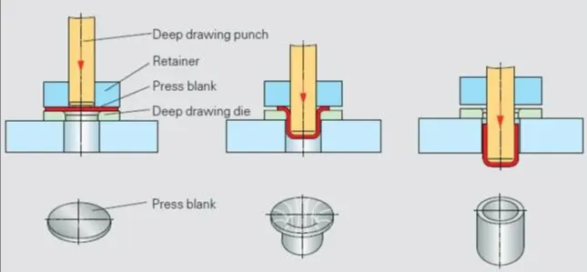
The stress in the flange region during the deep drawing process is a combination of radial tensile drawing stress and a tangential compressive stress (hoop stress). The main defects of deep drawn parts are wrinkling and/or necking. Wrinkling usually occurs at the flange region by excessive compressive stresses leading to local buckling of the sheet. On the other hand, necking is due to the excessive radial tensile stress. The blank-holder at the top of the workpiece exerts a compressive force at the upper surface of the blank during the drawing process. By controlling the blank-holder force during the process, it is possible to control the flow of the metal into the die cavity. The blank-holding force is usually applied by the outer ram of a double-action hydraulic press or by a cushion in a single-action press. A proper blank-holder force can prevent wrinkling of the drawn cup and delay necking. A blank-holder force profile which starts from zero at the beginning of drawing and reaches a maximum, and then reduces to zero at the end of the process is desirable for minimizing frictional resistance at the flange area and eliminating wrinkling.
Embossing
Embossing is a metal forming process for producing raised or sunken designs or relief in sheet materials by means of matched male and female roller dies, theoretically with no change in metal thickness or by passing sheet or a strip of metal between rolls of the desired pattern.Various embosses were made in the hood inner panel by keeping in mind the following design considerations.
- Pedestrian safety during the frontal crash.
- This helps in weight reduction of the hood and also to dissipate the force during collision.
- The embosses were designed in such a way that the distance between the hood inner panel and the outer panel was kept 5 mm from the points it had to be attached to each other.
- Hinge emboss was done keeping in mind the striker and hinge axis correlation.
Hemming
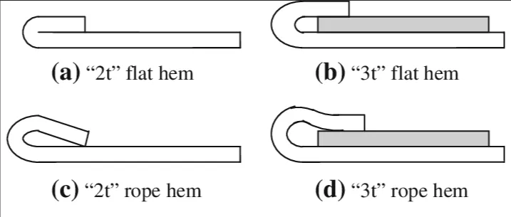
Hemming is a forming operation in which the edges of the sheet are folded or folded over another part in order to achieve a tight fit. Normally hemming operations are used to connect parts together, to improve the appearance of a part and to reinforce part edges. In car part production, hemming is used in assembly as a secondary operation after deep drawing, trimming and flanging operations to join two sheet metal parts together. Typical parts for this type of assembly are hoods, doors, trunk lids and fenders. The accuracy of the hemming operation is very important since it affects the appearance of the surface and surface quality. Material deformations, which occur during the hemming process, can lead to dimensional variations and other defects in parts. Typical hemming defects are splits or wrinkles in the flange, material overlaps in the corner areas or material roll-in.
There are various types of hemming operations:
1. Conventional die hemming: Conventional die hemming is suitable for mass production. In die hemming, the flange is folded over the entire length with a hemming tool. Normally the actual hemming is a result of a forming operation in which the flange is formed with a hemming tool after the drawing and trimming operations have been completed. The formed flange is then hemmed in several process steps. These steps include, for example, the pre-hemming and final hemming depending on the respective opening angle of the flange. Production plants for conventional die hemming are very expensive, but the cycle times are very low.
2. Roll hemming: Roll hemming is carried out incrementally with a hemming roller. An industrial robot guides the hemming roller and forms the flange. Roll hemming operation can also be divided into several pre-hemming and final hemming process steps. Roll hemming is very flexible to use and tool costs are significantly lower as compared to those of conventional die hemming. However, the cycle times are much higher since the hemming is realized using a hemming roller which follows a defined path.
4. CONCLUSION :
Creating a hood panel with given dimensions and provide hemming data.