Hood design-Week 2
OBJECTIVE:
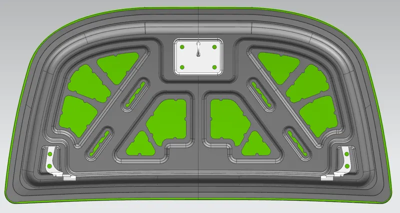
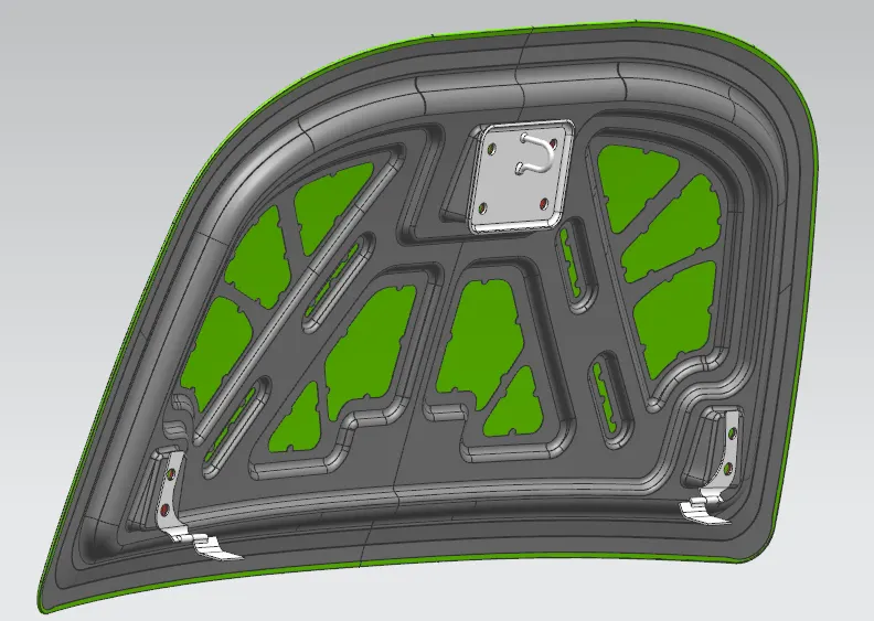
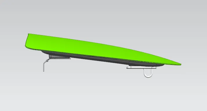
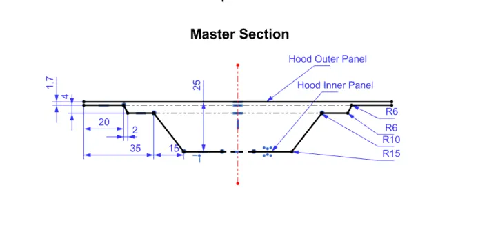
Design Hood Outer Panel, inner Panel and the necessary reinforcements by following the Master Section between the panels, and add hinge, striker into the assembly.
THEORY:
Hood or Bonnet of a car is BIW enclosure, it is hinged cover that rests over the engine of a front-engine vehicle. Hoods are usually made from the same material as the rest of the body. This can be steel, aluminum, fiberglass, or carbon fiber. Its purpose is to provide access to the engine for repair and maintenance. In design perspective there lot of things to be consider like, strength of the hood assembly, opening angle, impact on hitting etc. A concealed latch is typically used to hold down the hood. The hood assembly is an important system in a car from the safety point of view and has a direct relationship with the appearance aspect of the car.
Hood Assembly consist of
- Hood outer panel
- Hood inner panel
- Latch and striker
- Hinge
DATA GIVEN:
For designing the inner panel of the hood:
Hood Thickness Information
- Outer Panel Thickness = 0.75mm
- Inner Panel Thickness = 0.75mm
- Reinforcement Thickness = 1.5mm
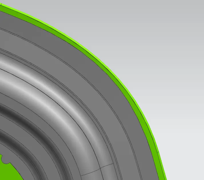
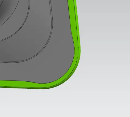
Give a relief at the corners with a 3 mm
COMPONENTS:
1. Hood Outer Panel
This part of the hood assembly is provided by the styling team. From a design perspective, the outer panel provides an aesthetic look for a car. Nowadays pedestrian safety and walker safety are very important in designing the outer hood. It also depends on the safety rating of the car, and there are lots of studies going on. The inner and outer panels are held together using hemming, it is very important to give hemming and relief at the corners. We use a mastic sealant in between the panels for reducing vibration during motion.
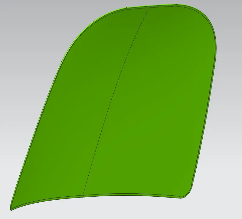
Front Relief and Rear Relief:
2. Hood Inner Panel
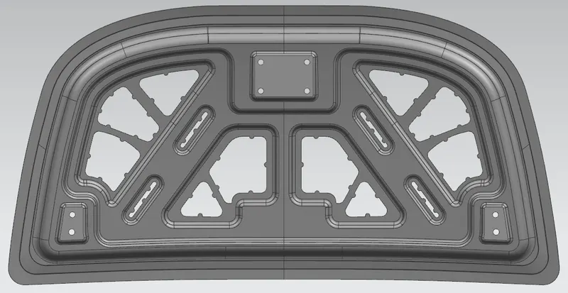
Hood inner panel for a vehicle is provided to improve rigidity, durability, and pedestrian protecting performance by comprising a composite structure. We design the inner panel with respect to the master section, other than this we give design embosses. And we provide an area for hinge and latch striker assembly..
3. Reinforcement
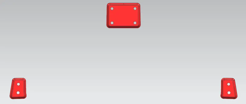
It is given with respect to design requirements, mainly it is given in hinge, and striker areas for giving extra strength locally. Reinforcement is given extra to the thickness of the inner panel. Usually reinforcement thickness is highr than the inner panel thickness, and the thickness will according to requirements and cost.
4. Striker
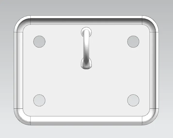
Strikers are hooks or bolts that latch up the hood and vehicle. The striker is designed to create a tight fit between the hood and the cab.
5. Hinge Assembly
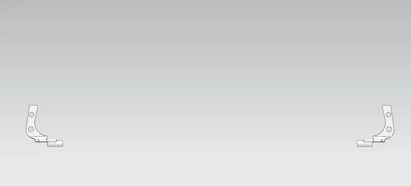
The automotive door hinge helps to close, open, and keep the open-angle of the hood.
6. Latch Trajectory
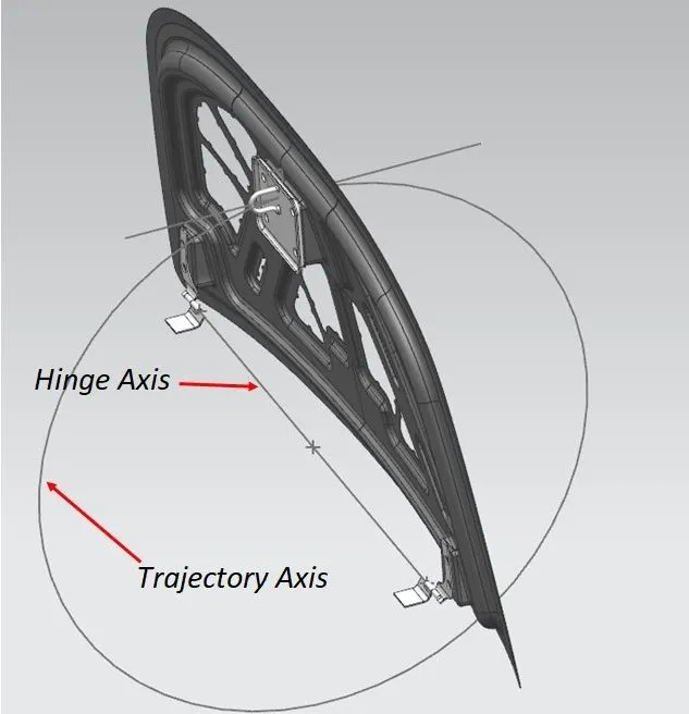
It is an imaginary path, but it helps place the striker with respect to the hinge position. First, we make a 3D line connecting the hinges axis that is placed on the hood inner panel and marks a mid point at the 3D line, taking that as the center point of the trajectory circle. We can find the position of the striker on the hood inner panel.
7. Embosses Definition
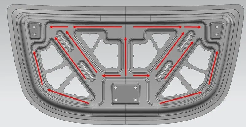
It is provided at the inner panel of the hood assembly, it gives stiffness to the inner panel and it helps to direct the force on an impact or collision. It ensures more safety to passengers. This emboss definition is designed such a way that force is directed towards the corners. And the design will change with respect to the requirements.
8. Mastic Data
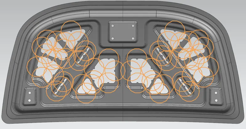
Hemming helps to hold the inner and outer panel together only at the end, it doesn't provide proper bond between the panels, so we need to provide bonding in between them. But the conventional techniques like welding, reviting will make marks on the outer panel that will effect the asthetic look. So the solution is Mastic bond .It can be used to fill the gaps between panels and provide resistance to the vibration. They are elastic in nature and they act like rubber, each mastic point has an effect of around 80mm diameter. It covers the area away from hemming.
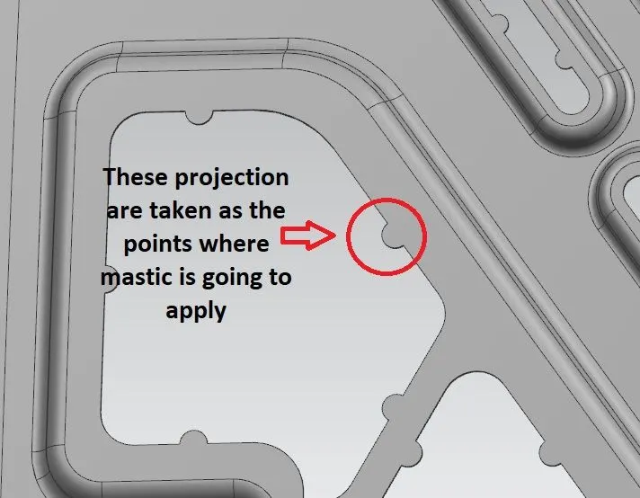
Example:
Manufacturing Processes
1. Deep Drawing
Deep drawing is one of the most widely used processes in sheet metal forming. Apart from its use in many other sectors, it is applied in the automotive industry for the manufacturing of car body parts. The deep drawing process is a forming process that occurs under a combination of tensile and compressive conditions. A flat sheet of the metal blank is formed into a hollow body open on one side or a hollow body is formed into a hollow body with a smaller cross-section.
The blank is placed over an open die with the help of blank holder. The blank holder provides a necessary force to hold the blank. The punch which is attached with a mechanical or hydraulic press moves downward and provide a necessary drawing force at blank. This force tends to deform metal sheet and forces it into the die cavity and convert it into a desired shape (it will change with respect to the die shape). If this force is high it causes elongation of walls to thin and if excessive, it causes tearing of sheet. So the punch force should remain a certain limit to avoid tearing during operation
2. Hemming
Hemming is a forming operation in which the edges of the sheet are folded or folded over another part in order to achieve a tight fit.
Normally hemming operations are used to connect parts together, improve the appearance of a part, and reinforce part edges.
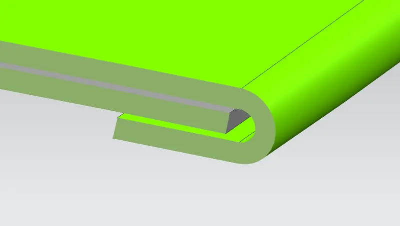
In-car part production, hemming is used in assembly as a secondary operation after deep drawing, trimming, and flanging operations to join two sheet metal parts (outer and inner) together. Typical parts for this type of assembly are hoods, doors, trunk lids, and fenders.
The accuracy of the hemming operation is very important since it affects the appearance of the surface and surface quality. Material deformations, which occur during the hemming process, can lead to dimensional variations and other defects in parts. Typical hemming defects are splits or wrinkles in the flange, material overlaps in the corner areas, or material roll-in. This is why it is important to use simulation tools in order to, on the one hand, better understand the hemming process and, on the other hand, significantly reduce the number of “trial and error” loops during tryout and production.
There are various types of hemming operations:
- Conventional die hemming
- Roll hemming
Conventional die hemming is suitable for mass production. In die hemming, the flange is folded over the entire length with a hemming tool. Normally the actual hemming is a result of a forming operation in which the flange is formed with a hemming tool after the drawing and trimming operations have been completed.
A rolling hemming uses a special foot on your sewing machine – called the rolled hem foot, appropriately enough – to roll the edge of the fabric onto itself and stitch it in place.
Final Assembly