Hood design-Week 2
Aim:
To create a Outer and Inner Panel of a car Hood ( Bonnet) from given Clas A surface.
Explanation:
A car hood, also referred to as a bonnet in some other countries, is the hinged cover that rests over the engine of a front-engine vehicle. Its purpose is to provide access to the engine for repair and maintenance. A concealed latch is typically used to hold down the hood.It is made up of sheeet metal and it is placed along the latch and strikers trajectory. Hood is very important in a vehicle as it provides as a shield for the engine and engine bay as there are many parts and components in the engine bay . Nowadays hoods are of different shapes and sizes as they play a major role in aerodynamic of a vehicle. In the case of outer panels in a vehicle the the requirement of pedestrian safety along with light weight structural rigidity has increased over the years and now let us look into them.
Bonnet Side Reference Line
The Bonnet Side Reference Line is defined as the geometric trace of the highest points of contact
between a straight edge 700mm long and the side of a bonnet, as defined in leading edge and A-Pillar,
when the straight edge, held parallel to the lateral vertical plane of the car and inclined inwards by 45
is traversed down the side of the bonnet top and A-Pillar, while remaining in contact with the surface
of the body shell, any contact with door mirrors is ignored. Multiple or continuous
contacts occur the most outboard contact shall form the bonnet side reference line.
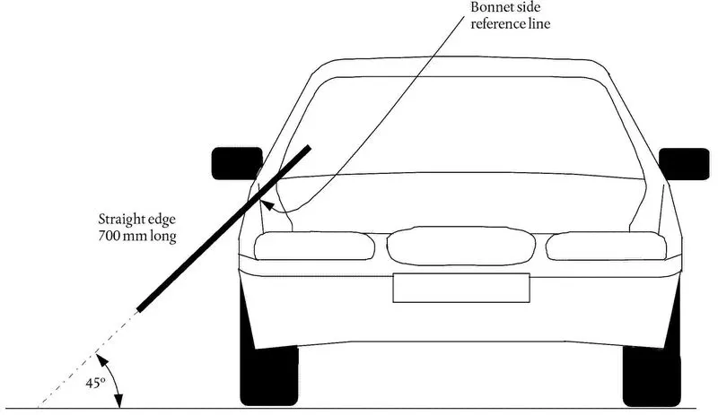
Fix a straight edge that is 700mm long at 45 to the vertical. With this edge in a plane parallel
to the lateral vertical plane of the car, position the straight edge at the front of the front wing
and in contact with, the bonnet.Mark the uppermost point of contact of the straight edge and wing.Pull the straight edge away from the wing, move it towards the other end of the vehicle by
not more than 100mm and then back into contact with the wing.Mark the uppermost point of contact of the straight edge and wing. Repeat moving the edge along the length of the wing, A-Pillar and Cant Rail if required (depending on the anticipated position of the 2100 Wrap AroundDistance).Using a flexible rule, join the marks on the vehicle to form a line. This line may not becontinuous but may ‘jump’ around the wing/wheel arch.Repeat for the other side of the vehicle. A partial modification of the side reference lines may be necessary subsequent to the determination of the corner reference points.
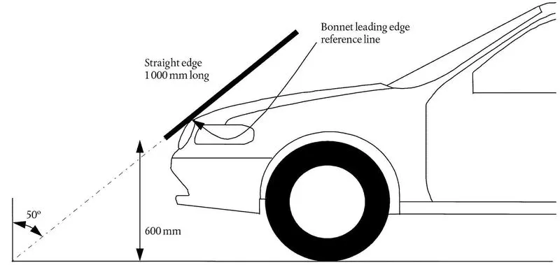
Bonnet Leading Edge Reference Line
The Bonnet Leading Edge Reference Line is defined as the geometric trace of the points of contact
between a straight edge 1000mm long and the front surface of the bonnet, when the straight edge, held
parallel to the vertical longitudinal plane of the car and inclined rearwards by 50 and with the lower
end 600mm above the ground, is traversed across and in contact with the bonnet leading edge, see the figure below. For vehicles having the bonnet top surface inclined at essentially 50, so that the straight edge
makes a continuous contact or multiple contacts rather than a point contact, determine the reference
line with the straight edge inclined rearwards at an angle of 40. For vehicles of such shape that the
bottom end of the straight edge makes first contact then that contact is taken to be the bonnet leading
edge reference line, at that lateral position. For vehicles of such shape that the top end of the straight
edge makes first contact then the geometric trace of 1000mm wrap around distance will be used as the
Bonnet Leading Edge reference line at that lateral position. The top edge of the bumper shall also be
regarded as the bonnet leading edge, if it is contacted by the straight edge during this procedure.
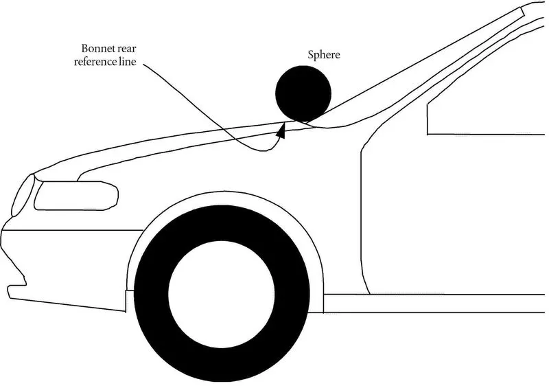
Bonnet Rear Reference Line
The Bonnet rear reference line is defined as the geometric trace of the most rearward point of contact
between a 165mm sphere and the frontal upper surface, when the sphere is traversed across the frontal
upper surface, while maintaining contact with the windscreen.Remove the wiper blades and arms. Place a 165mm sphere at the vehicle centreline on the frontal upper surface so that therearmost point of contact of the sphere is always on the glass.Mark the most forward point of contact between the sphere and the vehicle’s frontal uppersurface. Repeat this at suitable increments moving outboard until the sphere contacts the side
reference line on both sides of the vehicle. Refer the image below.
If the bonnet rear reference line is located at a wrap around distance of more than 2100mm,the bonnet rear reference line is defined by the geometric trace of the 2100mm wrap arounddistance. Where the bonnet rear reference line and side reference line do not intersect, the bonnet rearreference line is extended and/or modified using a semi-circular template, of radius 100mm.The template shall be made of a thin flexible sheet material that easily bends to a single curvature in any direction. The template shall, if possible, resist double or complex curvaturewhere this could result in wrinkling. The recommended material is a foam backed thin plasticsheet to allow the template to ‘grip’ the surface of the vehicle.
Marking Wrap Around Distances
The headform test area is defined as the outer structure that includes the upper surface of all outer structures. It includes, but is not limited to, the bonnet, wings, windscreen scuttle, wiper arms/spindles, windscreen frame, A-pillars and roof. It is bounded by the geometric trace of the1000mm wrap around line in the front, the Bonnet Side Reference Lines and the 2100mm wraparound distance (WAD). Begin at the vehicle centreline. Place the end of a flexible tape measure or graduated wire on the floor vertically below thefront face of the bumper.Wrap the tape or wire over the bumper, bonnet windscreen and roof ensuring that it ismaintained in a vertical longitudinal (X, Z) plane and that its end is still in contact with theground. The tape should be held taut throughout the operation, vertically below the front faceof the bumper, see Figure below.
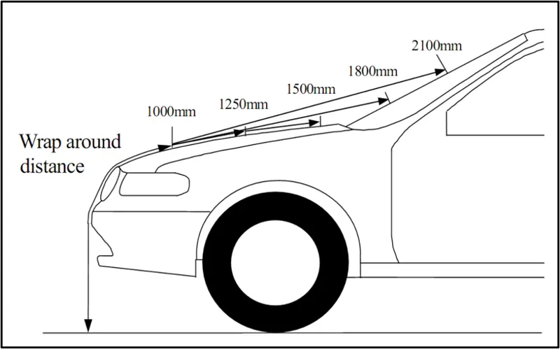
Mark on the bumper/grille, bonnet top, windscreen, A-pillars and/or roof the wrap around distances of 775mm, 930mm, 1000mm, 1500mm, 1700mm and 2100mm. These are thegeometric traces described on the outer surface of the vehicle by the end of flexible tape or wire 775mm, 930mm, 1000mm, 1500mm, 1700mm or 2100mm long, when it is held in a vertical fore/aft plane of the car and traversed across the front of the bonnet and bumper. Where any of the WAD’s lie below the outer contour of the vehicle, for example in the gap
behind the bonnet, using the tape or wire approximate the outer contour of the vehicle horizontally rearward from the last point of contact and project the WAD vertically down onto the underlying structure. Reposition the end of the tape on the ground no further than 100mm laterally outboard starting at the vehicle centreline up to the Corner of Bumper. The tape should be stretched over the A-pillars where necessary. Repeat steps until the width of the vehicle has been marked up to the Side Reference Lines. Join the points marked on the bonnet to form lines at wrap around distances of 775mm,930mm, 1000mm, 1500mm, 1700mm and2100mm. Points located from 1000mm to1500mm WAD inclusive will be assessed using the child/small adult headform. Points from 1700mm to 2100 mm WAD inclusive will be assessed with the adult headform, Where the bonnet rear reference line is between 1500mm and 1700mm WAD, points forward of and directly on the bonnet rear reference line will be assessed using the child/small adult impactor. Where the BRRL is rearward of 1700mm WAD, the child/small adult headform shall be used up to and including 1700mm. Points rearward of the bonnet rear reference line between 1500mm and 1700mm WAD will use the adult impactor.
Now as we have the Euro-Ncap criteria of Hood Design let us develop a Hood from given Class A.
Design Procedure:
- First we have a Class A of Hood given to us by the styling team. So we take that Surface and split it into two halves as we can later symmetry or mirror the splitted half to get a complete surface.
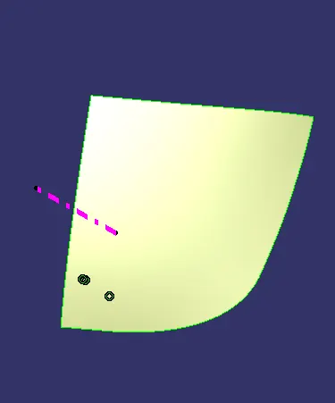
The above shown imgae is the splitted half of the Class A surface.
- The we offset the splitted half to a distance of 2mm on the under side of the class A and take the boundary of the surface and offset that boundary using parallel curve to a distance of 20mm and spilt it as we need only the outer surface.
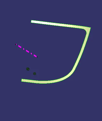
The above shown image is the splitted suface which is offseted to 2mm.
- And we repeat the same process but this time we offset it to 4mm on the downside and split the surface at 35mm and keep the oter surface.
- Next we do the same process but here we offset the surface to 25mm on the downside and split at 50mm and keep the inner side of the surface.
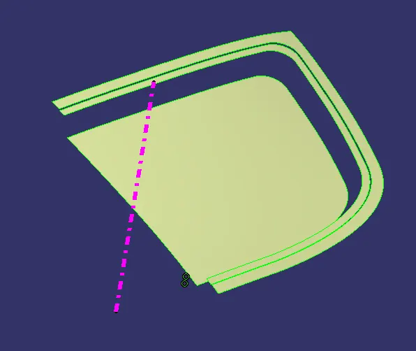
The image above shows all three offeted surface.
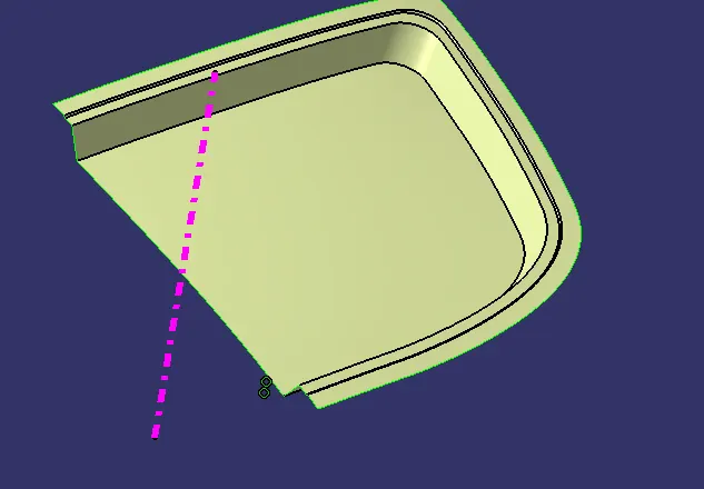
The above shown image shows all three surface joined using sweep or extrude and later joined to make it a single surface.
- Now we sketch on the surface of third offset for emboss purposes and we split the surface according to ou design with keeping in mind leaving a space fro striker and hinges.
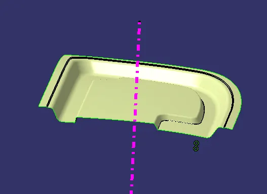
Embossed image.
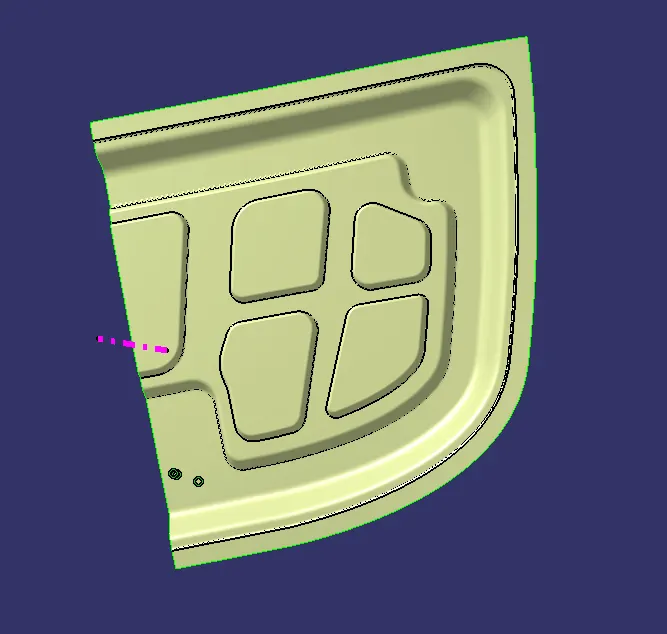
And now we create another layer of emboss for the mastic points positioning.
Mastic point are areas where the inner hood panel is joined with the outer panel hem using a mastic glue. This mastic glue keeps the inner panel stuck to the outer panel. The main purpose of the outer panel is for the aesthetic look.
- Now we create place for mastic points by sketching and splitting the surface .
- Later we position the hinges in a its axis and we randmly place it in its place and extract the lower surface of the hinge where it is going to be fixed to the bonnet and sweep its boundary and trim it with the bonet surface and make it into a single surface.The placement of hinges is done after symmetrying the embossed surface.
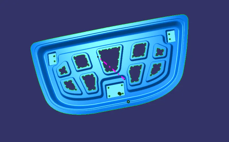
The above shown image is the final inner panel without the hinges and striker.
- The striker and the hinges are given to us and the images are shown below.
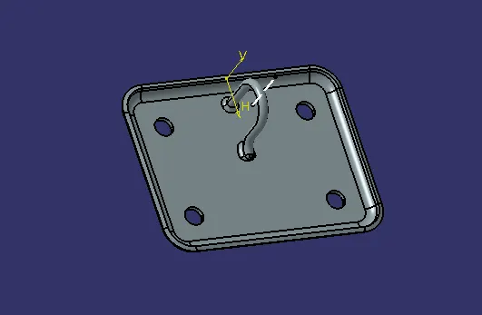
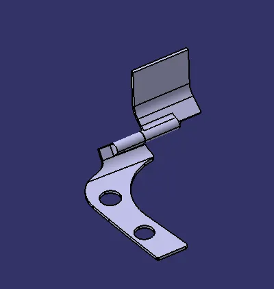
- Now Hemming process, Hemming is the process in which the edge is rolled flush to itself, while a seam joins the edges of two materials. Hems are commonly used to reinforce an edge, hide burrs and rough edges, and improve appearance.
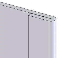
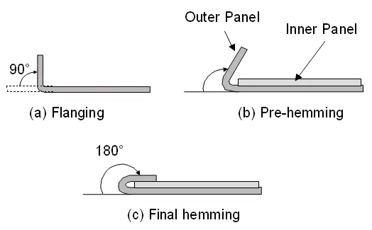
The above shown images depict how hemming is carried out.
For this we offset the Class A surface on below the iner panel at a distance of 0.75mm(width of hemming surface)+0.75mm(width of inner panel)+0.75mm(width of outer panel)+0.20mm( clearance). And after it is offseted we use multisection and join the surface and wrap around the ine panel.
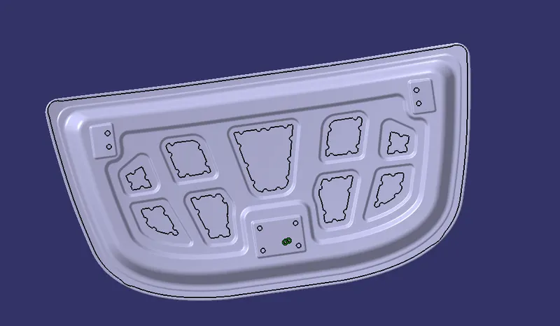
The above shown image is outer panel and inner panel along with hemming.
The image below is the final Hood design,
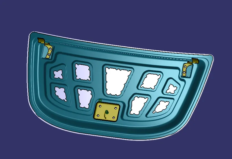
- The Outer panel and the inner panel is then thickened as measurements shown below.
Hood Thickness Information
- Outer Panel Thickness = 0.75mm
- Inner Panel Thickness = 0.75mm
- Reinforcement Thickness = 1.5mm
After everything is done the striker and hinge surface which come in contact with the Inne panel for attchment is extacted to create a reinforcement .
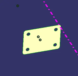

And after placing the striker and hinge reinforcement our model or design is fully complete and ready for poduction after checking with the CAE team.
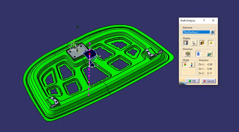
Draft Analysis on the Hood: