Hood design-Week 2
Designing and Assembling of Hood
Introduction
Hood Often called as Bonnet which is situated in front side of Cars. They mainly are for closure of Engine compartments and component which is situated at the front side. They also serve a purpose of protecting passenger inside the car and pedestrians during the event of accident/incident.
Definitions
- Latch: It is the material used in hood for closing/holding the hood within the body, when you pull the knob inside the car to open the hood, the hood latch cable opens the latch.
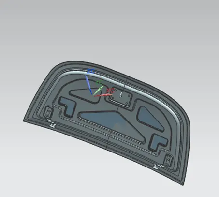
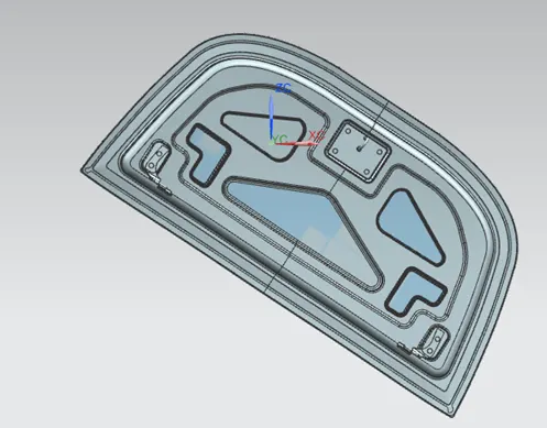
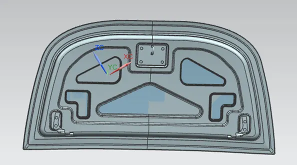
- Inner Panel of Hood: The inner panel of the hood is generally not visible to the people but it is the replica of the outer panel with engineering features embedded within.
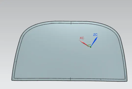
- Outer Panel of Hood: Outer panel is a smooth surface which will be holding the inner panel.
- Emboss: Embossing is a metal stamping process for producing raised or strip between rolls of the desired pattern
- Offset: It is bringing the shape of curve either inside/outside for required diameter
- Law Extension: It is Extending an existing surface or sheet based on the laws for distance and the angle of the extension
- Hemming: It is a process in which sheets are joined by bending it
Designing of Inner Panel
- Offset the surface of the outer panel
- The offsetting process should be as per the required dimensions
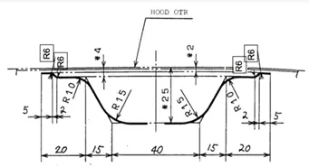
- After making the three offsets as per the requirement of dimensions, the make a through curves
- Trim the unwanted areas using Trim and Extend.
- Then the areas are covered up using through curves feature
- The through curve feature we enable a curve to connect from one point to another
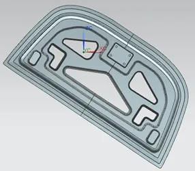
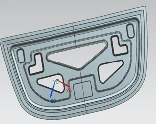
- Now create a sketch opposite to inner panel and project the sketches inside inner panel
- Using the feature Emboss select the sketch and make it emboss
- You can do emboss using offset geometry and law extension features
- Law extension feature extend the feature from one surface with angle to another
- Once the emboss is create using the feature of edge blend, blend the edges
- Using the feature face blend bend the required faces
- Trim the unwanted areas
- Using the feature mirror geometry, mirror the geometry
- You can extended and trim with respect to plan and also mirror the geometry
- Examine the geometry for gaps
- Sew the geometry
Assemblying of Hinge
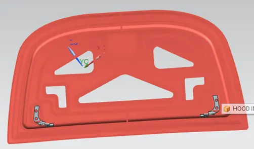
- Insert the componet
- Move the component near the place were the hinge requireds to be placed using move component feature
- Once the required area is obtained then using feature Geomentry constrians, coonstrain it with the inner panel
- The constrains used will be parallel to the plane and Distance align
- Once the hinge is fitted to required area then mirror the assembly
- While mirroring it should be selected with associative mirror to obtain a opposite mirror images
- Make a line from hinge axis to mirror hing axis
Assemblying of Striker
- From the axis created in the hinge, from the center point create a circle which is parallel to Y axis
- Then create a tangent facing ooposite to the inner panel
- The tangent must be joined on the circle and create a center line
- Once the refence are created. Insert the part in assemble and bring it close to the point need to be placed
- Create a reference point on the striker, the refernce point should be constrained with the tangent on the circle.
- Fix the end point and start point
- Create a zone using wave gemonetry linker and emboss the geomentry to the body
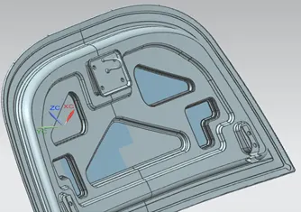
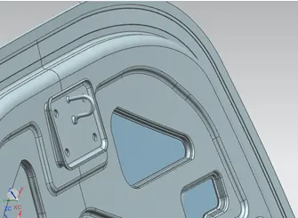
Outer Panel
- Offset the outer panel and use the feature of law extension
- Again offset to required dimension to obtain middle layer
- Again offset to required distance to obtain outer layer
- Using trim and extend, trim the unwanted areas
- Using three face blend feature, blend the three layers
- To get a correct region on corner use curve of surface and trime the section
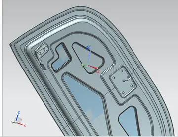
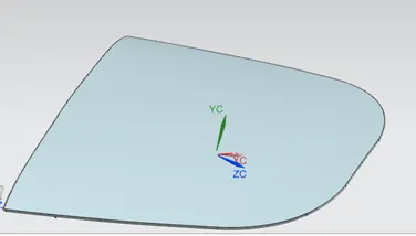
Feature Tree
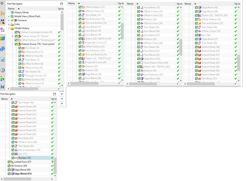
Outer Panel Feature tree
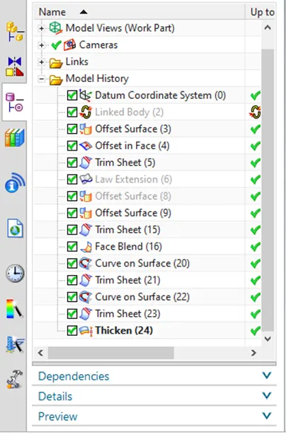
Assembly feature tree
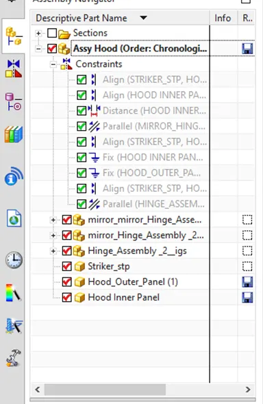
Designed Images