Photo Realistic Rendering
Title
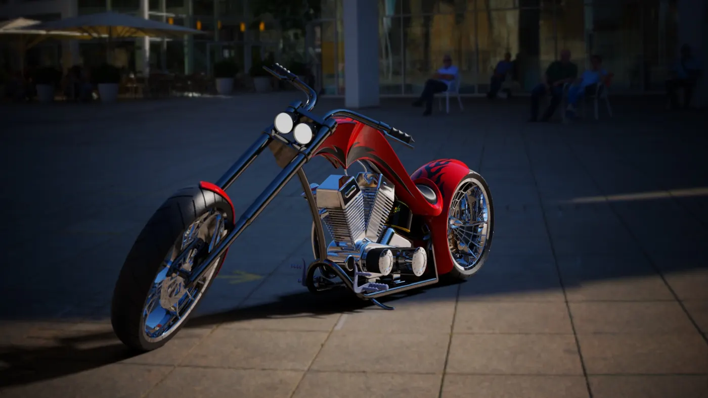
Design and Assembly of American Chopper using SolidWorks
Introduction
The report describes about Designing, Modeling, and Assembling of American Chopper using SolidWorks and Rendering the model using SolidWorks Visualizer to get output as required
Objective
The main objective is to Model American chopper and explore with various tools and its abilities using SolidWorks.
The Modeling is done by various steps but this report consists of
- Individual Part Modeling
- Assembling of Individually modeled part
- Rendering to get natural Output
Definitions
- Transmission: It is the speed-changing gears and the driveshaft by which the power is transmitted from an engine to a live axle
- Kick Stand: It is a metal rod attached to a bicycle or motorcycle, lying horizontally when not in use, that may be kicked into a vertical position to support the vehicle when it is stationary.
- Fender: Fender is the American English term for the part of an automobile, motorcycle or other vehicle body that frames a wheel well. Its primary purpose is to prevent sand, mud, rocks, liquids, and other road spray from being thrown into the air by the rotating tire
- Chain: A chain is a roller chain that transfers power from the area to the drive-wheel of a vehicle, thus propelling it.
- Oil Tank: Tank for containing or storing oil
- Pedal: Tubular metal frame mounted on two sides of motor bike to rest leg and provide actions which will be a part in controlling the bike
- Wheel: A circular object that revolves on an axle and is fixed below a vehicle or other object to enable it to move easily over the ground
- Fork: A fork is the part of a bike that holds the front wheel. A fork typically consists of two blades which are joined at the top by a fork crown. The crown is often at the front.
- Fuel Tank: Tank for containing or storing Fuel
- Engine: A machine with moving parts that converts power into motion or a machine designed to convert one form of energy into mechanical energy.
- Chassis: A chassis is the load-bearing framework, which structurally supports the object in its construction and function
- Plane: A plane is a flat, two-dimensional surface that extends infinitely far. Plane can be described by Top, Bottom and Center
Description
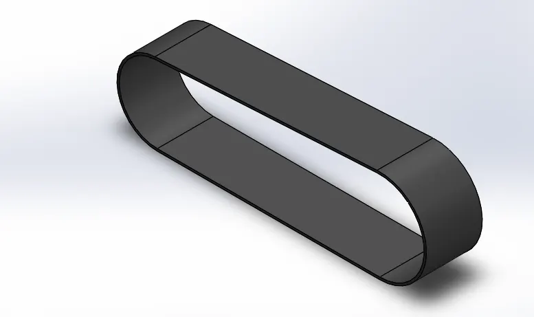
- Transmission
Features: Boss Extrude/ Base and fillet
This part is created by sketching into Front plane. The profile is created with a line, 3 point arc followed by Extrude. Extrude is a feature which convert the 2D sketch into 3D.Apply fillet for the sides. Once the design part is completed it can be saved with a file name.
- Kick Stand
Features: Lofted Boss/Base, Dome, Extrude cut, Boss Extrude/ Base and fillet
This Part is created by sketching in Right Plane. The profile is created by two ellipse followed by a patch which joins the center of two ellipse. The path can be joined using pierce relation to center or directly joining on the center points. Loft is the feature which is used for creating the body of stand. Dome feature is used to create the rounded end. Extrude cut feature is the feature used create a cut on top end which joins the chassis. Once design part is completed it can be saved with file name.
- Chain
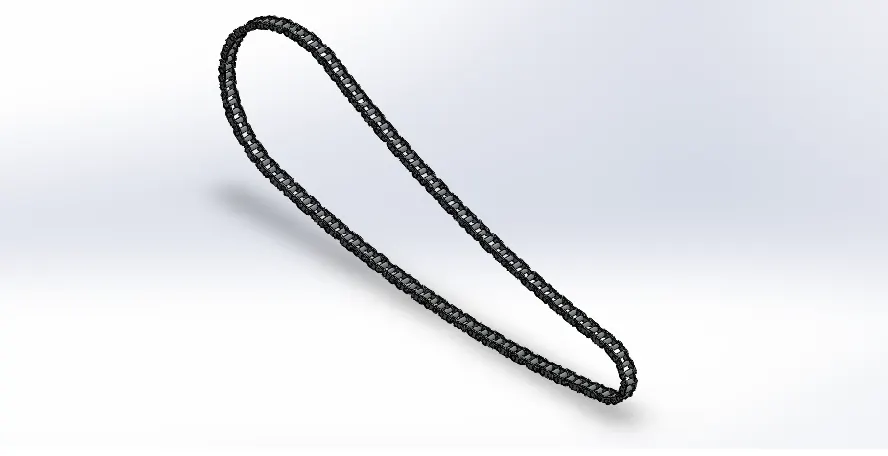
Features: Boss Extrude/ Base, fillet, Circular pattern, Mirror, Combine
This part is created with 3 point arc and line with tangency. In this two inner and outer links of the chain is been created with circles and lines. The link is extruded and they are to be saved as nodes. Those links are to be linked with actual chain sketch and features like curve driven pattern and liner pattern to be used at the appropriate sections. Once all the links are set the final chain link to be manually drawn to confirm that it gets perfect with the other links. The inner, outer chain links and the pins can be stored in folder to avoid confusion. Once all are completed the appearance has to be set to chrome steel.
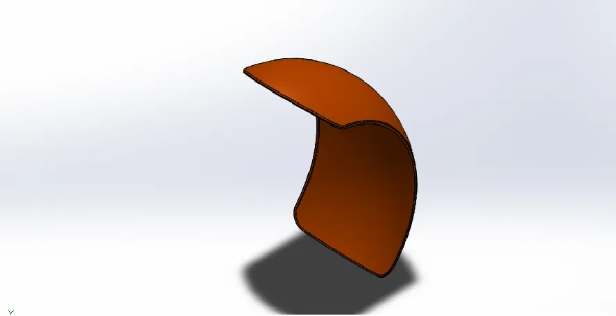
- Rear Fender
Features: Boss Extrude/ Base, fillet, Shell
This part is created by sketching in front plane. It is created by using a 3 point arc and feature like offset is used, the reference line from the origin has been created in order to use the feature revolve in which the face is created additional feature like fillet is used to convert sharp edges to smooth one. The appearance for the part can be created using render tool and save the part with file name
- Rear Wheel
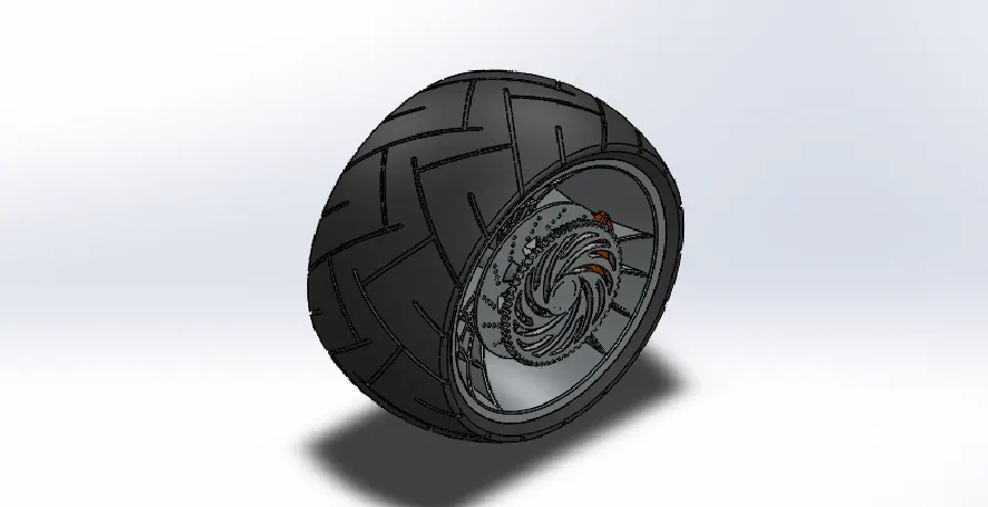
Features: Boss Extrude/ Base, Revolve Boss/Base, Extrude cut, Revolve cut, Circular pattern, Mirror, Combine, Chamber and fillet
In this part we are going to create four integral parts such as
- Rotor
- Caliper
- Sprocket
- Tire
The part Rim is created by sketching in front plane by revolving with the imaginary/ reference axis then the part is extruded. On the Extruded part a sketch is created like a spider web which will indicate the rims, the same sketch is extruded from mid plane using feature Extrude- MidPlane. The entire web feature is constructed using spline and three point arc. The unnecessary regions are trimmed using power trim and the same is mirrored with the reference.
Rotor is created by sketch in front plane and on the face of rotor circles are created and made an extrude cut. Then the circles are expanded using circular pattern.
Caliper is created from the reference of rotor by using lines and arc joining. The part is then Extruded using Midplane extrude feature. The fillet Chambers are used to make the sharp surfaces as smooth.
Sprocket is created using a circle. On the circle a sketch will be performed in order to bring teeth for the sprocket, then the sketch will be made with an extrude cut up to next feature and the cut region will be expanded using circular pattern along with the applied fillets
Tire is created by using the feature of Convert Entities of the rim. Using that as reference the tire is revolved. On revolving the tire will have a good face, on that face geometry will be created using midpoint rectangle. Those sketches will be aligned and given dimensions and will be cut with extrude cut feature for getting the pattern of grips. Once those are done it will be expanded using Circular Pattern feature.
Finally all body will be given an appearance with render tool and will be saving with file name
- Front Tire
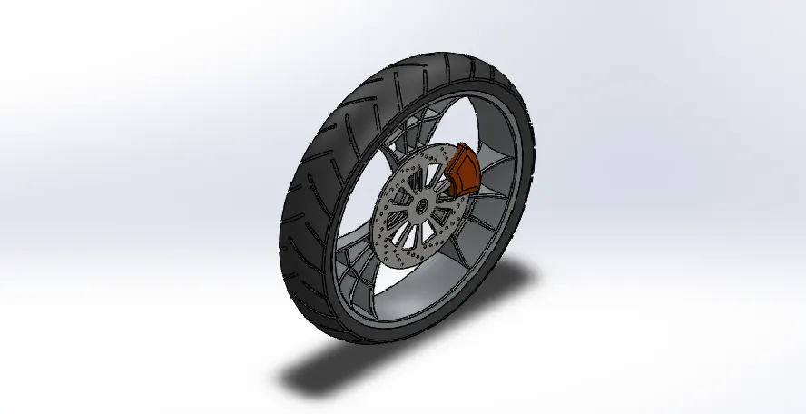
Features: Boss Extrude/ Base, Revolve Boss/Base, Extrude cut, Revolve cut, Circular pattern, Mirror, Combine, Chamber and fillet
In this part we are going to create four integral parts such as
- Rotor
- Caliper
- Tire
The part Rim is created by sketching in front plane by revolving with the imaginary/ reference axis then the part is extruded. On the Extruded part a sketch is crated like a spider web which will indicate the rims, the same sketch is extruded from mid plane using feature Extrude- MidPlane. The entire web feature is constructed using spline and three point arc. The unnecessary regions are trimmed using power trim and the same is mirrored with the reference.
Rotor is created by sketch in front plane and on the face of rotor circles are created and made an extrude cut. Then the circles are expanded using circular pattern.
Caliper is created from the reference of rotor by using lines and arc joining. The part is then Extruded using Midplane extrude feature. The fillet Chambers are used to make the sharp surfaces as smooth.
Tire is created by using the feature of Convert Entities of the rim. Using that as reference the tire is revolved. On revolving the tire will have a good face, on that face geometry will be created using midpoint rectangle. Those sketches will be aligned and given dimensions and will be cut with extrude cut feature for getting the pattern of grips. Once those are done it will be expanded using Circular Pattern feature.
Finally all body will be given an appearance with render tool and will be saving with file name.
7. Pedal
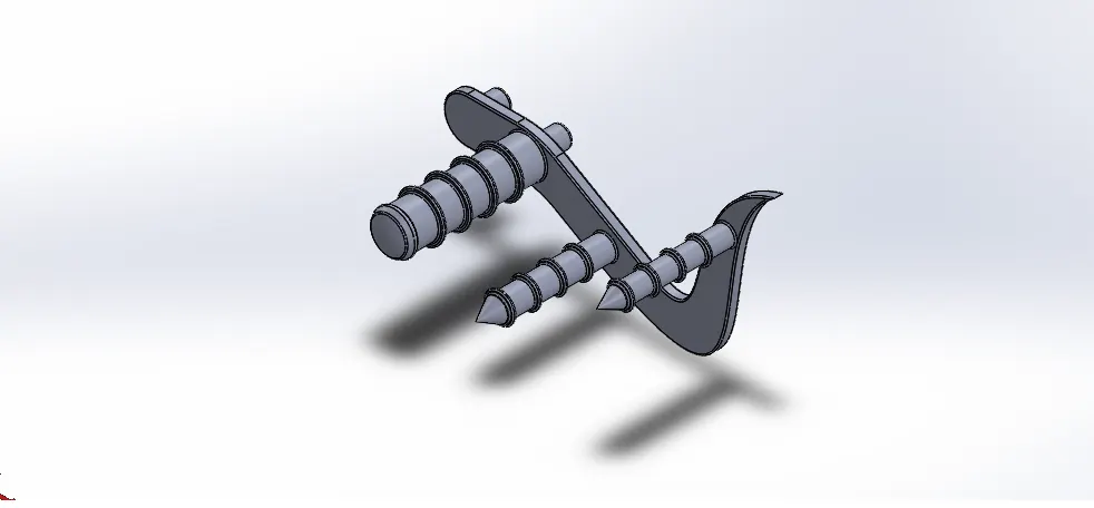
Features: Boss Extrude/ Base, Revolve Boss/Base, Dome, Linear pattern, Chamber and fillet
This part is made by sketching in the front plane by lines and curve then it is extruded. On the face of extrude the circles are drawn and it is extruded out for required dimension to fit into the chassis then on the extruded circles one more circle is drawn by converting entities, then its multiplied by using linear pattern. Then the part is provided with chrome steel appearance using render tool.
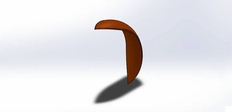
8. Front Fender
Features: , Revolve Boss/Base, fillet, Split and Shell
This part is sketched in front plane using 3 point arc and offsetting in order to obtain thickness an axis is created and the sketch is revolved to get the face of front fender. The two different sketch are created in Top and Right plane to cut the fender to obtain required shape. The fillets are used to make the edges smooth and appearance is created using render tool.
9. Oil Tank
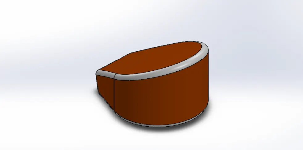
Features: Boss Extrude/ Base, Combine, Shell and fillet
This part is created by sketching on top plane using 3 point arcs and lines and it is then extruded. In the front plane another extrude is created with midplane feature. Then spilt feature is used to remove unwanted parts in the profile. Shell feature is used to obtain the hollow structure within the part. Appearance is created to the part using render tool.
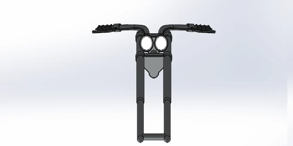
10. Front Fork
Features: Boss Extrude/ Base, Revolve Boss/Base, Extrude cut, Revolve cut, Projected curve, Sweep Boss/Base, Dome, Mirror, Combine, Chamber and fillet
This part is created in front plane sketching a line and revolving with reference axis. Then the frame for fork is been created and extruding. On the same plane head light is sketched and been revolved with reference axis. On the frame a sketch is created with line and spline and sweep feature in order to obtain the handle. Then the sketch is mirrored using a reference plane and then it is combined using combine feature. Appropriate appearance is created for the body using render tool. The head light is made in an illusion of glowing through lights feature in render tool.
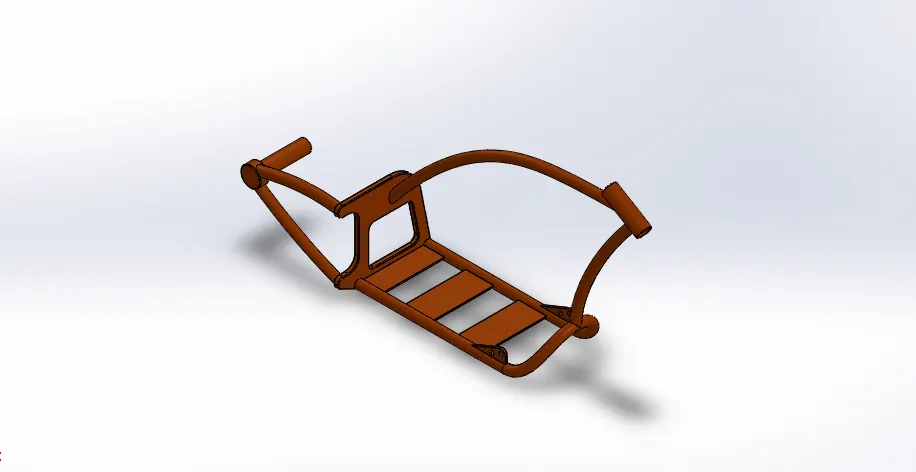
11. Chassis
Features: Boss Extrude/ Base, Revolve Boss/Base, Extrude cut, Linear pattern, Revolve cut,Projected curves, Sweep Boss/Base, Dome, Mirror, Chamber and fillet
The Blue print of the chopper is inserted on the plane which we start to sketch and the sketch is created by using lines, arc and spline. A feature of projected curve is used in order to make 2D curve into 3D. Then it is mirrored and combined into single part. Appearance is created using render tool.
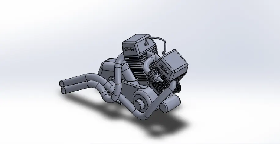
12. Engine
Features: Boss Extrude/ Base, Revolve Boss/Base, Extrude cut, Revolve cut, Circular pattern, Projected curves, Swept Boss/Base, Dome, Mirror, Combine, Chamber and fillet
The blue print of the chopper is inserted in the plane were we need to sketch. The sketch is proceeded with 3 point arc and lines with tangency and the extruded. In the front plane one set of engine is created and mirrored using a reference axis. A sketch is created as circle for pulley using revolve feature. A circle is created in front plane and a spline is created in opposite plane then projected using projected curve the same sketch is been swept by using sweep feature to obtain the exhaust. Finally spark plugs are crated and appearance is given using render tool.
13. Fuel Tank
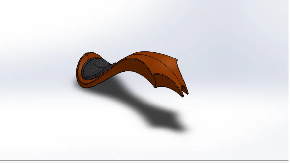
Features: Swept Surface, Loft surface, Boundary Surface, Projected curves, Knit Surface, Sweep cut, Combine, Chamber, Shell, Mirror and fillet
This part is created by sketching on the front plane using spline and projected curve and surface sweep is used to create half of the tank. Another sketch is created on the tank for seat and extruded. The entire body is mirrored using reference plane and knit feature is used to knit the surface together. Appropriate appearance is used for the part from render tools
Assembly of Chopper
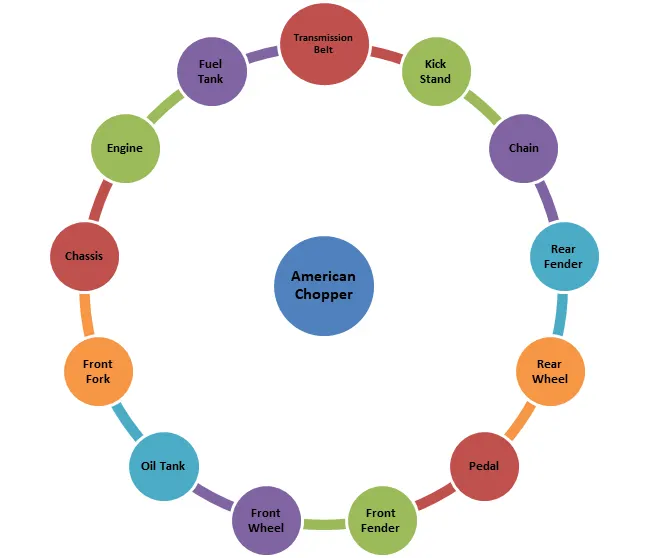
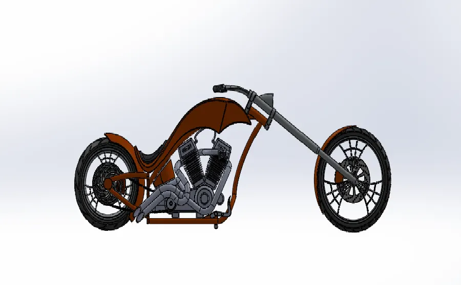
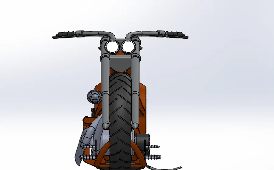
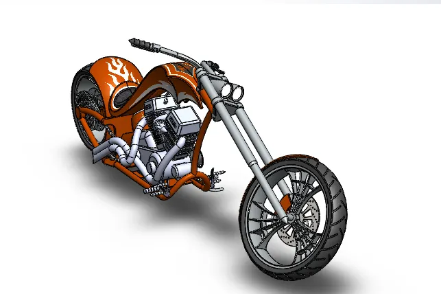
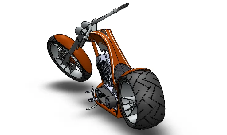
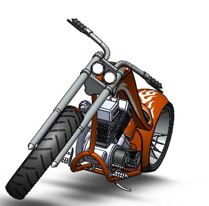
To assemble we need to open assembly section and insert all part designs. Keeping the Chassis as a reference and each part needed to be assembled. The parts can be rotated to desire one using the axis. The assembly will be done using parallel, concentric and coincident relations. The decals can be inserted using the render tool.
Assembled Chopper
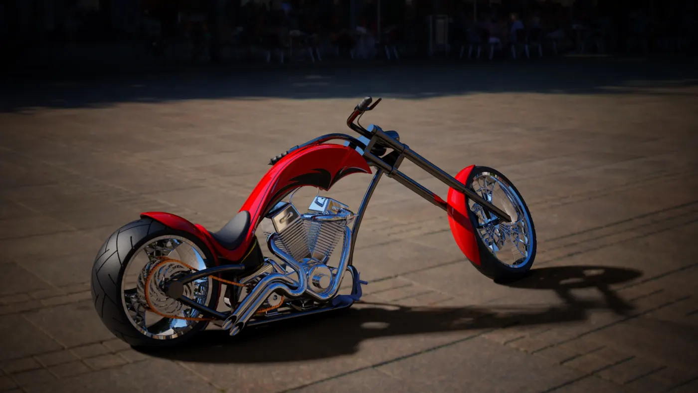
Creating a Final Render Using SolidWork Visualizer
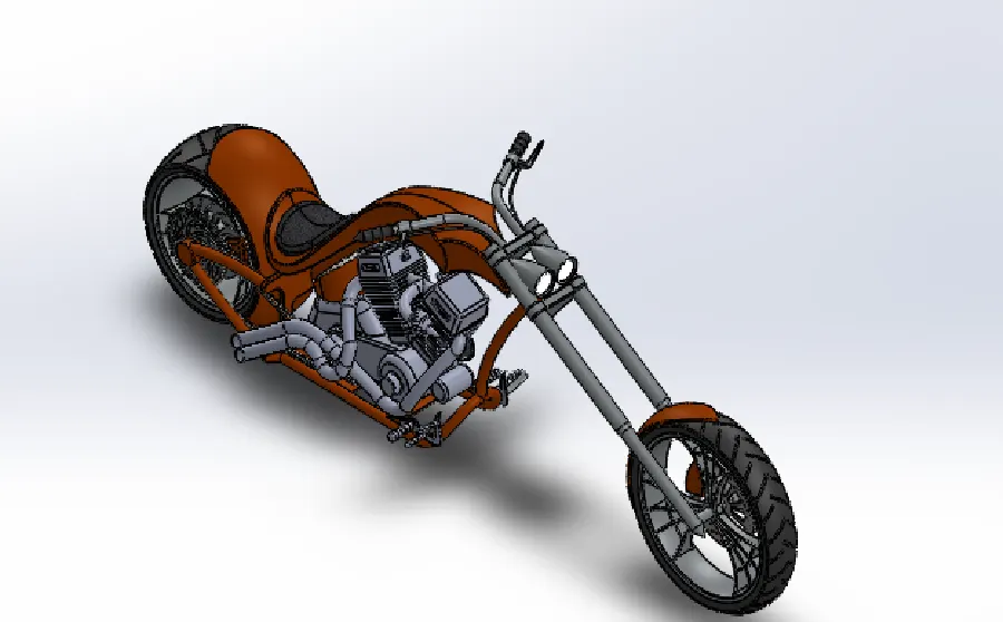
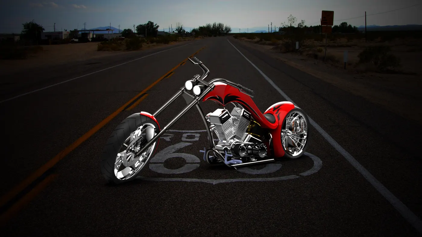
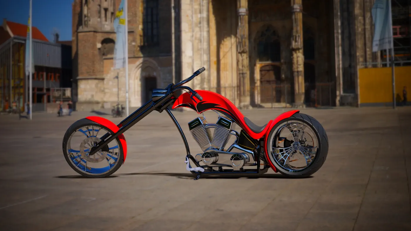
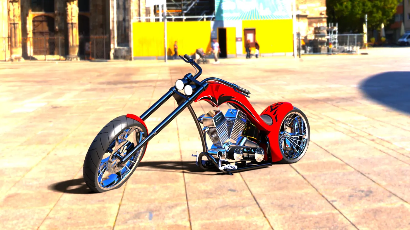
The assembly is taken into Solidworks visulaizer and its backgroud are changed by inserting a background and the brightness is adjusted and it is allowed for final render.
Conclusion
Thus the project Design, Assembly and Rendering of American Chopper using Solidworks has been created and completed successfully.