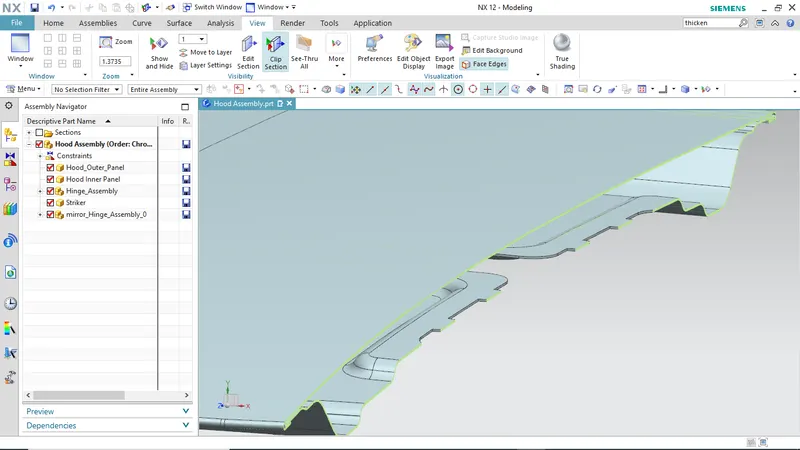
Hood design-Week 2
HOOD DESIGN
Objective-To create the design of the car hood with inner panel, Outer panel, Striker and required reinforcement.
The software used for this design-NX 12
The following steps are used in this design
- Develop the inner panel
- Develop the outer panel with hemming data.
- Providing the proper embossing
- Providing mastic data
- Positioning all the reinforcements
Master section data which is given in this design
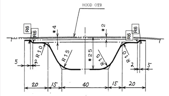
Data to be used
Outer panel Thickness =0.75 mm
Inner panel Thickness = 0.75 mm
Reinforcement Thickness = 1.5 mm
Hood: -
The car’s hood consists of ana inner panel and an outer panel. The inner panel provides strength, while the outer panel is just a metal cover. The underside of the hood is often covered with a sound absorbing material.
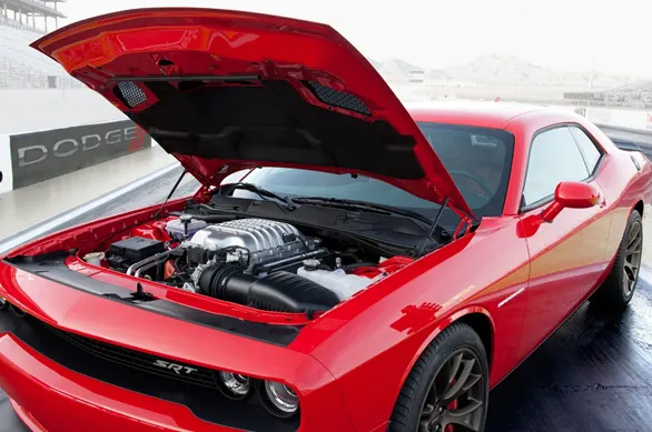
The hood or bonnet is the hinged cover over the engine of motor vehicle that allows access to the engine compartment for maintenance and repair. On passenger’s car, hood may be held down by a concealed latch. On rare cars or cars with after market hoods the hood may be held down by hood pins. Hood are typically made out of steel or aluminium although aftermarket manufacturers may manufacture hoods out of fibre glass, carbon fibre or dry carbon.
Purpose of Hood Design
- Safety of the passenger
- Covers all engine, radiator and other necessary components.
- Reduce air affect due to its aerodynamic shape design
- Reduce engine noise which helps for a quitter drive
- Provide access to engine maintenance
- Absorbs most of the impact forces when a frontal crash occurs
Design and Manufacturing of the Car hood
The front hood has been cut from general assembly shapes of an electric prototype vehicle. The design of this it was done using CATIA V5 software. It was performed behind it based on the shape of the external surface of the model. The hood are some fixing points and reinforcements zone for its hardening this element was modelled in according with similar element from actual cars.
Head clearance criteria-
Head clearance is decided up on the zone or country. So same car if it is made for different country will have different opening angle depending on the country or region.
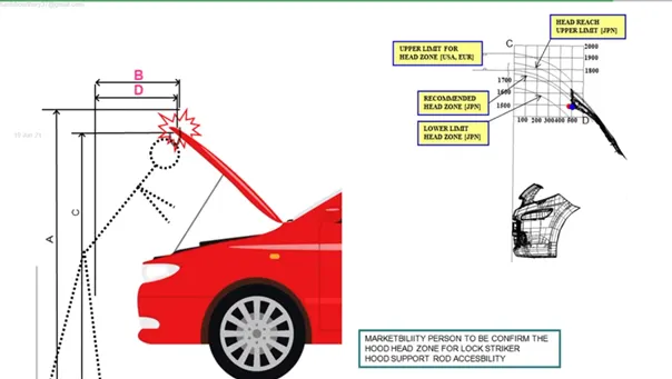
The distance C and D shown in the image is represented as graph in the upper right corner of the image. Choosing the right head zone position will decide upon the angle of the hood opening.
Wrap Around distance (WAD): -
The distance on which the head impacts on the car from the ground level is called Wrap around distance.
To be specific the wrap around distance is a measurement of distance from the ground to the head impact zone over the outer surface of the car.
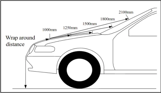
The WAD plays an important role in the safety measurement of the pedestrian. During the crash analysis based on WAD, two test areas will be created namely child head impact zone and adult head impact zone. The child head impact zone is between 1000 to 1700 mm and the adult head impact zone ranges between 1700 to 2100 mm WAD.
Pedestrian Safety Measures-
Euro NCAP the European car assessment program is European car safety performance assessment program based in leaven and founded in 1997.
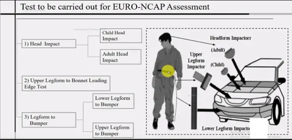
They publish safety reports in new car and awards star ratings based on the performance of the vehicle in a variety of crash test including front side and pole impacts with pedestrian.
So here in hood we separate the whole area of hood in to several small part /region during frontal crash. Hood is the major portion a person is going to come in contact with. So, Euro NCAP specified some guidelines under which we distribute hood region in to several parts and try to get more green region.
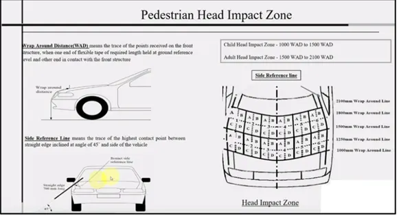
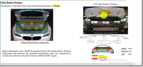
This region is basically distributed in relation to the height of children and adults who come in contact from front wheel accident. So here the main moto is to achieve greener region and for that we provide splits in embosses so that during head impact the consequences of collision come less effective. So here I have given splits accordingly to improve head impact zone effectiveness in providing less damage to the person who hit it.
Types of hood support
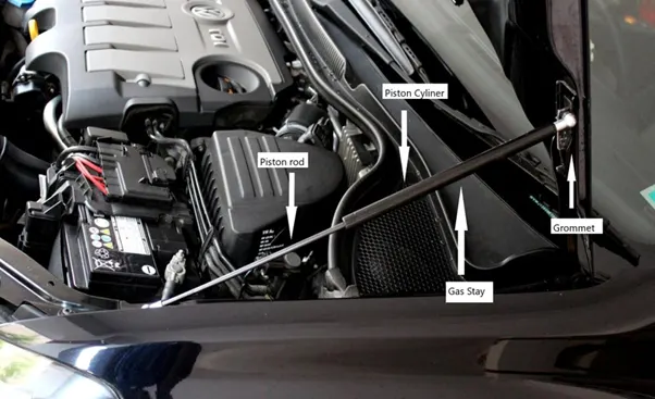
1.Gas stay: -
These are used to lift the car hood or bonnet its purpose to just give the lifting force to the hood, then it automatically opens the car hood by means of gas pressure. This is used where the car bonnet size is heavy to lift.
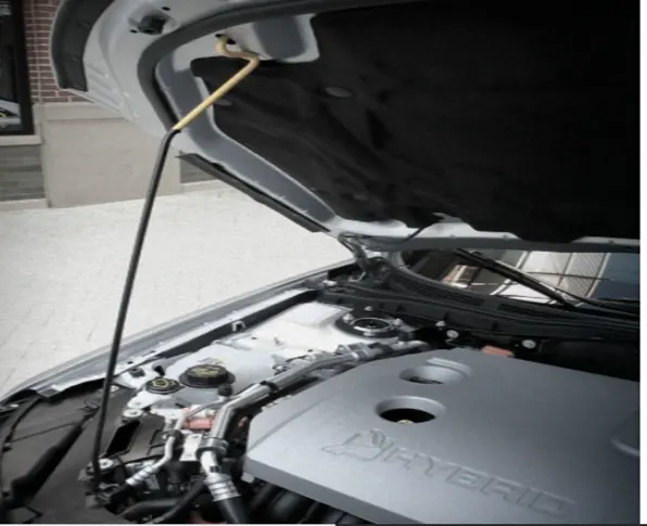
2.Support rod: -
This is widely used in many cars because this is very easy and cheap. In this type we have to lift the hood by ourselves and place the support rod in the space provided either in the hood or engine component. This is mostly used for where the car bonnet weight is small.
Deep Drawing: -
Deep drawing is one of the most widely used processes in sheet metal forming. Apart from its use in many other sectors, it is applied in the automotive industry for the manufacturing of car body parts.
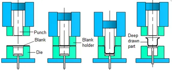
The deep drawing process is a forming process which occurs under a combination of tensile and compressive conditions. A flat sheet metal blank is formed into a hollow body open on one side or a hollow body is formed into a hollow body with a smaller cross-section.
Deep drawing processes are divided into three types:
- Deep drawing with tools
- Deep drawing with active means
- Deep drawing with active energy
The rigid tools consist of a punch, die and binder. In deep drawing, the plate holder closes after the metal sheet blank has been inserted. Next the sheet is clamped between the die and the binder.
This process slows down the flow of the sheet while it is being drawn and thereby prevents wrinkles from forming under the binder. The punch stretches the sheet over the die radius and forms it in the die.
The amount of punch force necessary for forming is thereby continually increased up to the lower dead centre of the punch. Whereas in pure deep drawing there is no reduction of sheet metal thickness, forming is achieved in stretch forming purely as a result of a decrease in sheet metal thickness. Stretch forming is extensively used for the forming of only slightly curved parts with low depth of draw (e.g. roofs, doors).
Hemming Process: -
Hemming is a forming operation in which the edges of the sheet are folded or folded over another part in order to achieve a tight fit. Normally hemming operations are used to connect parts together, to improve the appearance of a part and to reinforce part edges.
Given data for hemming
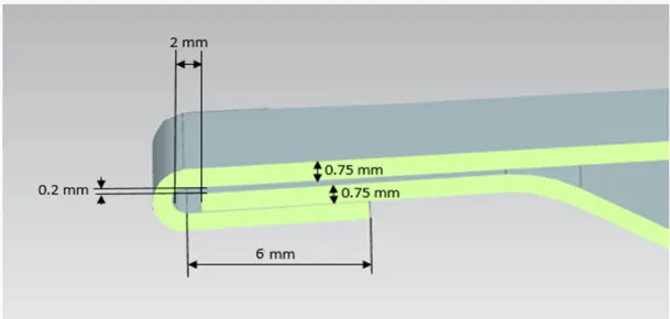
I have created
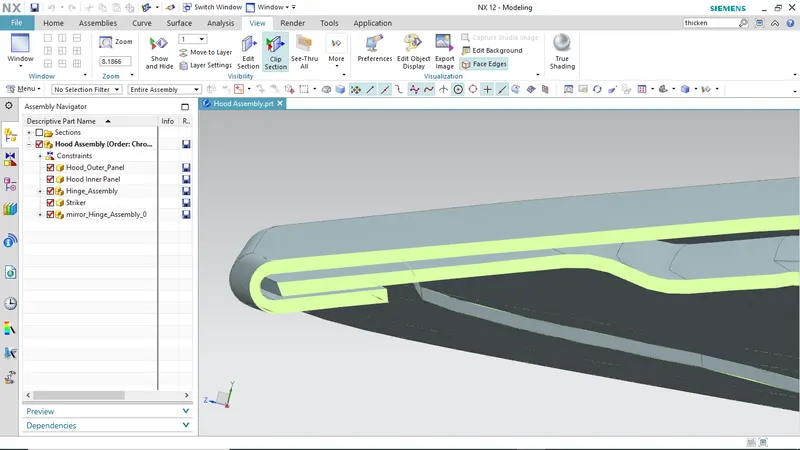
In car part production, hemming is used in assembly as a secondary operation after deep drawing, trimming and flanging operations to join two sheet metal parts (outer and inner) together. Typical parts for this type of assembly are hoods, doors, trunk lids and fenders.
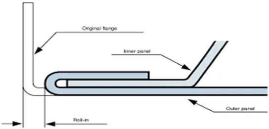
The accuracy of the hemming operation is very important since it affects the appearance of the surface and surface quality. Material deformations, which occur during the hemming process, can lead to dimensional variations and other defects in parts. Typical hemming defects are splits or wrinkles in the flange, material overlaps in the corner areas or material roll-in. This is why it is important to use simulation tools in order to, on the one hand, better understand the hemming process and, on the other hand, significantly reduce the number of “trial and error” loops during try-out under production.
There are various types of hemming operations:
- Conventional die hemming
- Roll hemming
Conventional die hemming :-
Conventional die hemming is suitable for mass production. In die hemming, the flange is folded over the entire length with a hemming tool. Normally the actual hemming is a result of a forming operation in which the flange is formed with a hemming tool after the drawing and trimming operations have been completed. The formed flange is then hemmed in several process steps. These steps include, for example, the pre-hemming and final hemming depending on the respective opening angle of the flange. Production plants for conventional die hemming are very expensive, but the cycle times are very low.
Roll hemming:-
Roll hemming is carried out incrementally with a hemming roller. An industrial robot guides the hemming roller and forms the flange. Roll hemming operation can also be divided into several pre-hemming and final hemming process steps. Roll hemming is very flexible to use and tool costs are significantly lower as compared to those of conventional die hemming. However, the cycle times are much higher since the hemming is realized using a hemming roller which follows a defined path.
Emboss-
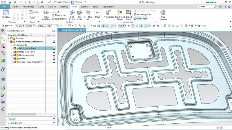
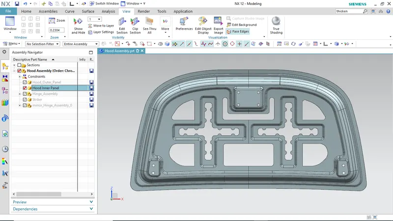
Emboss has been given to create extra strength in inner panel and embosses design needs to be inspired by force dissipation phenomena like here I have made embosses in a way if any object hit from front most of the force will get dissipated by its designed towards the upper left and right corner so that less force reaches at occupant’s end.
Mastic Points-
Mastic point are areas where the inner hood panel is joined with the outer panel hem using a mastic glue. This mastic glue keeps the inner panel stuck to the outer panel.
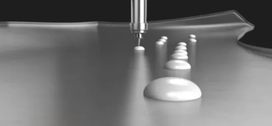
The main purpose of the outer panel is for the aesthetic look. Thus, we cannot use bolt or welding. This has to be done with the helps of the hemming and mastic sealants. Mastic sealants are elastic compound that behaves like rubber. It is placed between the outer and inner panel. Initially is it in paste form but after the hot furnace bath it gets hardened thus joining the outer and inner panel.
Mastic data-
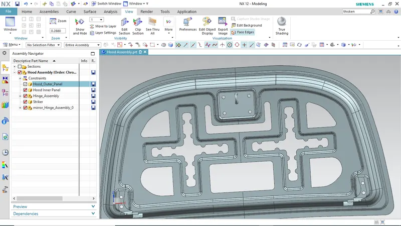
It is basically an NVH topic mastic are point/surfaces given on embosses for applying mastic sealant to joint inner panel and also give good value of NVH. One spot of mastic sealant provides strength locally at around 80 mm so we need to put these mastic points in such a way that it covers the most of the hood region except reinforcement area of latch and hinge because that alone provide good NVH so no worries there.
Trajectory for hood opening and closing-
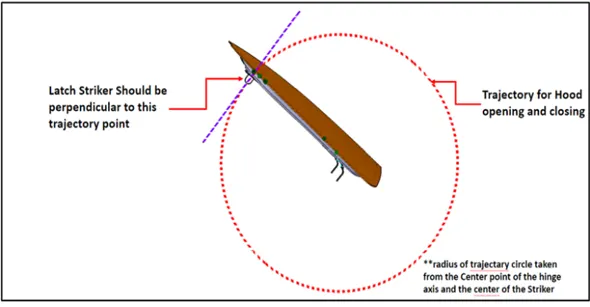
For the proper opening and closing of the hood the striker should be positioned at a correct position. The striker should be perpendicular to the trajectory of the hood. The flanges are positioned at their respective positions. Then the line is drawn at a straight. Now the trajectory is derived from the hinge axis and the centre distance from the striker.
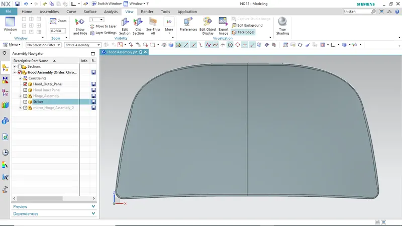
Hood Outer Panel
Front view
Hood inner panel
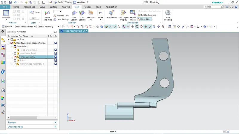
Hinge assembly
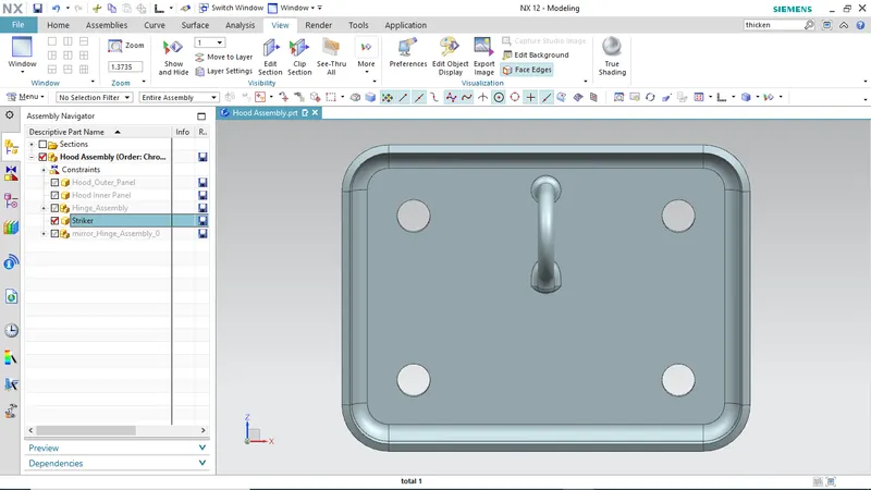
Striker
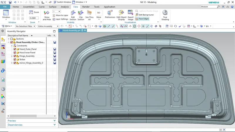
Final assembly
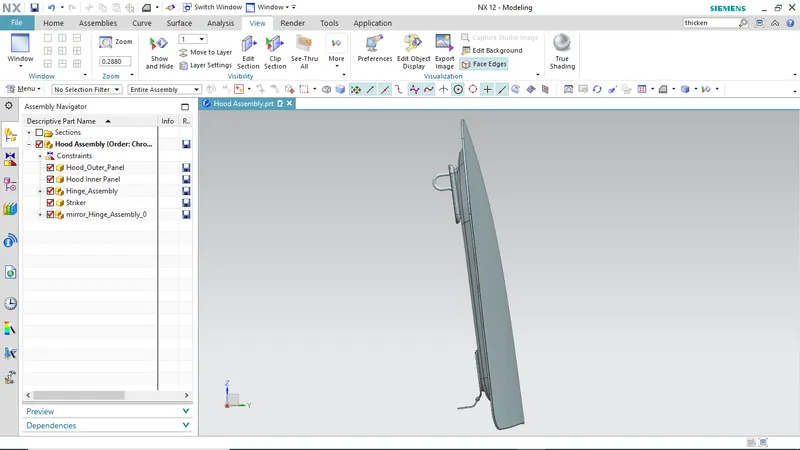
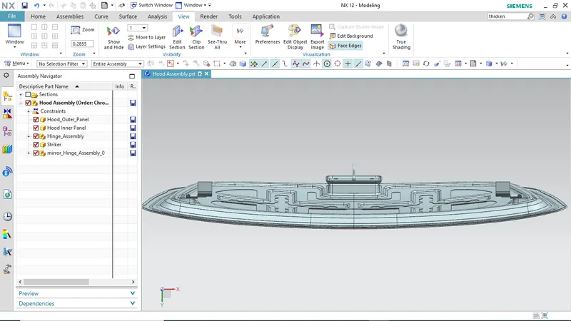
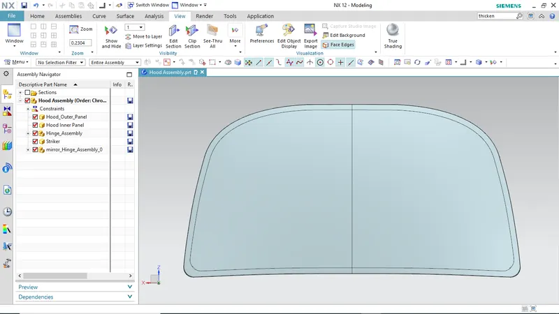
Section view