Hood design-Week 2
Step 1:-download all the files with master section of the hood design and extract it and save to folder and name it as hood design sheet metal.
Step 2:- Open file and choose a new file go to assembly name it hood design and save it to particular location and name it.
Hood outer panel:-
Step 3:- Go to new file and then model and name it as Hood outer panel and
In title bar there is Assembly click it and open it and in ribbon bar there is add part from source of file which are saved .
Step 4:-again do same procedure and new file and choose model part then go to assembly section and choose wave geometry linker and choose face and click OK.
Wave geometry linker:-this is tool through which we can extract part from previous model as it is and there is link between two.
Step 5:- go to Hood outer pane activate it then go to surface tool from title and go to trim sheet through ribbon bar.then choose singe face and central plane and section which one want to discard and keep.
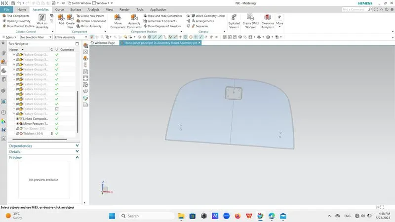
As per wave geometry linker hood outer panel reaction implement on hood inner panel also and cut its half portion also.
Step6:-To avoid this we will go to hood inner panel and linker section and setting and off tick to associative and click OK and then go to hood outer panel and delete trim sheet part .
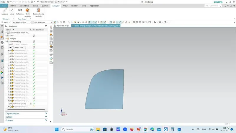
Tooling Axis Creation:-
Step7:- go to Inner panel and activate it then take side view of panel go to sketch and choose respective plane of XY and then take a line and join between two points of hood inner panel side view.draw a line through mid point perpendicular to line and constrain it.Crate a feature group for tooling axis.Finish Sketch
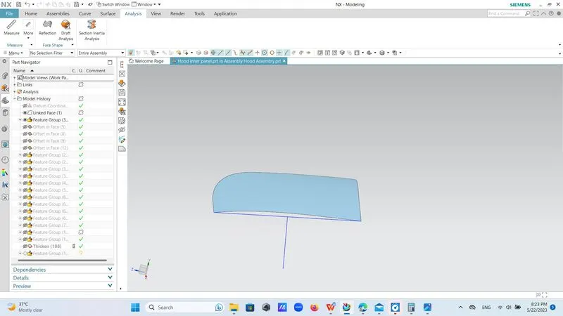
Step8:-Go to Inner hood panel and then surface from title tab and then offset surface in ribbon bar and click on it select face as single face and offset it by a distance of 1.7mm downward direction. And hide parent surface because we want to work on our offset-ed surface.
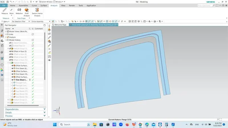
Step 9:-Go to the curve from title box and in ribbon bar there is offset curve in face select single curve can also take tangential curve so choose any one and take boundary of the surface then take a distance of 20mm and tick all the trim to face edge and extend to face edges from setting for proper selection of curve.then go to surface trim sheet and select that curve and select face single as surface and select surface to keep and discard.
Step10:-Go to the parent part of the hood and again offset it by distance of 4mm and then select offset curve in face and take distance of 22mm by doing same procedure offset it by distance of 35mm. Go to surface from title bar and then select trim sheet from ribbon bar and do selection of curve and select surface keep and discard option by clicking on surface that want to keep.
Step11:- again go to parent surface and offset it by distance of 25mm downward and then go to curve and offset face curve select tangential or single curve and offset it by distance of 35+15=50mm and go to select face and face go to trim face and choose inner face and discard outer portion and through surface .
Step 12:-Go to surface there is option of through curve and select curve as inner edges of the off seated surface and then create wall between two surfaces.
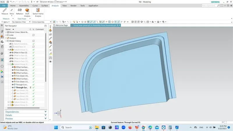
Step 13:-Go to face bland option from surface and take edges of surfaces as assure than direction of arrows are in same direction and give radius of 6mm for first two surfaces and then R10 and R15 for next two edges from master section.
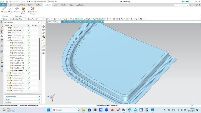
Step14:-Take normal face and take a plane x,y and direction of z axis is towards viewer sketch diagram by taking profile option by keeping 0.5 mm distance at least from all sides and start from a point on edge and ensure that sketch is not closed at this time and constrain it then finish sketch and select project curve option from given sketch and project it on surface in the direction of vector and click OK.
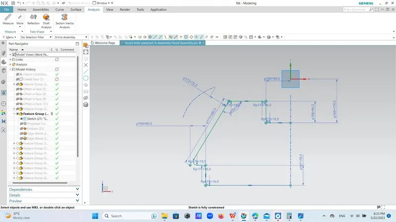
Step 15:- Now select surface option in title and more option from ribbon bar and select emboss option then select sketch as curve and surface as face and select emboss face in end cap -geometry location offset and distance as 8.5mm and angle as 12.
Note:- there is distance between two surfaces is 18.5mm so kept distance of 10mm for this.
Step16:- go to edge blend from surface and select edge blend from and give radius of 06mm to it.
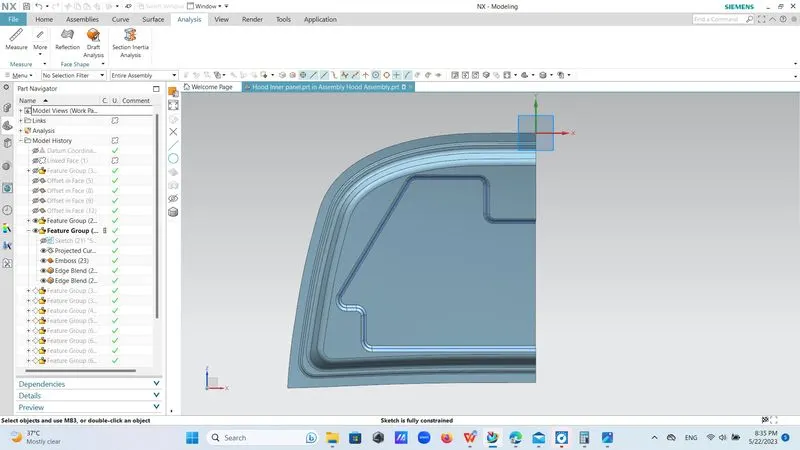
Step 17:-As above done before take a inferred plane x,y and then z direction reverse if needed and then draw a sketch on this plane and project it on face and then by going to surface from more option choose emboss and emboss it about 10mm and then by taking edge face option with radius of 6mm.
Note:- As before it had taken emboss distance of 10mm now take it as 8.5 mm so total is 18.5 we have to constrain between this value.
We have to do it for various shapes.
Note :- Emboss is done because gap between then is field with mastic which are provided to control to NVH that is noise vibration and harness as less as NVH rating is provided to model .
are elastic compound that behaves like the rubber. It is placed between the outer and inner panels. Initially is it in paste form, but after the hot furnace bath, it gets hardened thus joining the outer and inner panel. Mastic sealant can absorb shocks from both inner and outer panels thus reducing NVH.
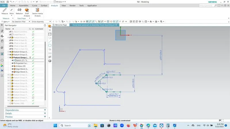
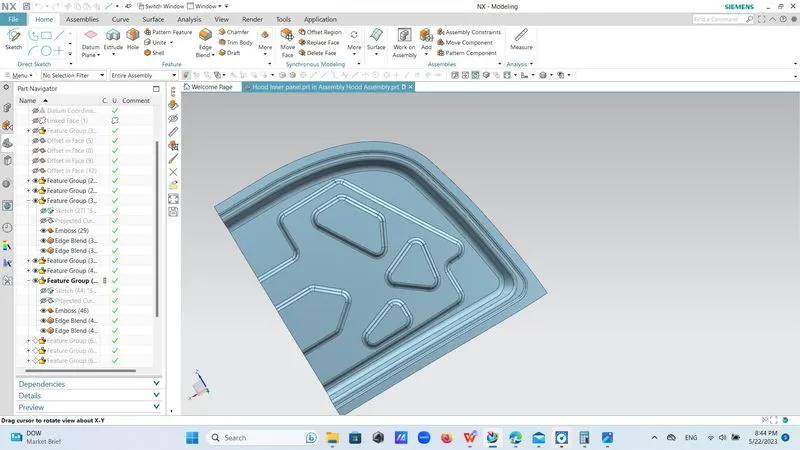
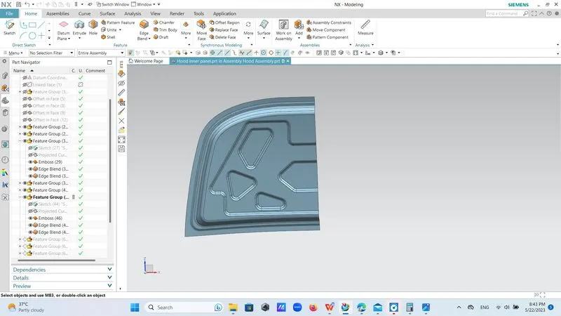
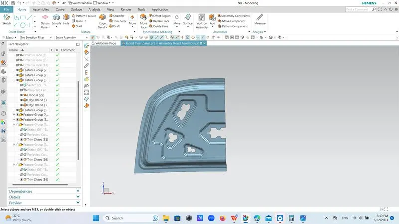
Step 18:-Cutting Operation:-As done before take new plane X,Y Plane and then draw a sketch on it project it on surface constrained it and then draw a circle pattern on boundary of that sketch and trim it outer side so to form half circle and past it on other sides then take surface trim option from surface and trim it.
Step19:-Hing Mounting:-
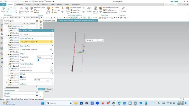
-Go to Assembly then add and add file which is data provided of hinge assembly and then take on datum plane choose at an angle select planner object as x,y plane and then angle taken as -7 deg. Which is almost parallel and nearer to x,y plane offset it by distance of 580mm from respective plane.
Draw a sketch on this datum plane and project it on surface and embossed it by distance of 7mm and draft option from end cap angle up to 10 OK.
Take edge blend of radius of 5mm .
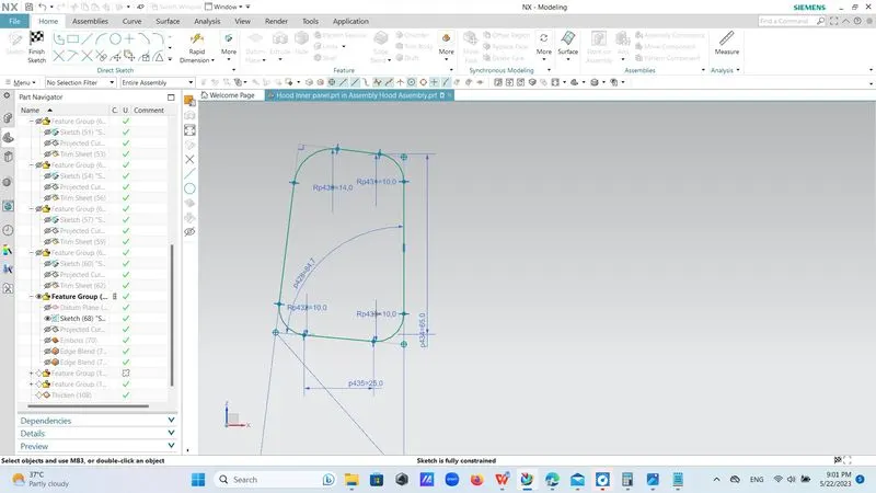
Step 20:
Mirror Geometry:
In menu option there is insert -associative copy -mirror geometry select the half hood pattern and Mirror plane as mid plane then sew them if there is gap between two surfaces then line will display on it so we could not offset pattern then go to surface select extend sheet and select edges if any edge can not select then press shift key and leave it go forward and after completion of this operation select remaining edges and then choose trim sheet option select mid plane and trim it then sew it .
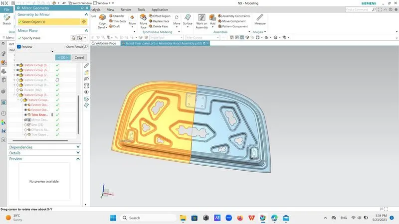
Step 21:-Datum Plane :
select datum plane from home option and then At an angle form selection panel then select reference plane and then direction of vector and then angle for plane is -7 deg selected and then offsect it by distance approximatly 700mm.
select that datum plane for sketch and constrain it on whicn hinge assembly can place and then emboss it by distance of up to 5mm.
go to Assembly constrain and choose touch align and take rear surface of hinge assembly and surface of emboss.
Then by using parallel constrain select axis of hinge and x axis of coordinator.
Then by using move component mount this hing assembly of surface .
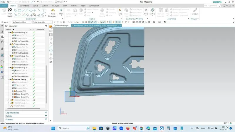
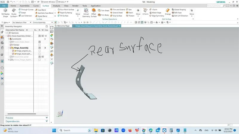
Step 22:- Go to menu -Associative copy - mirror feature and select hinge assembly and then mirror plane as mid plane.
go to assembly thrn wave geometry linker and then extract the holes of hinge assembly then go to surface and trim them.
Striker :-
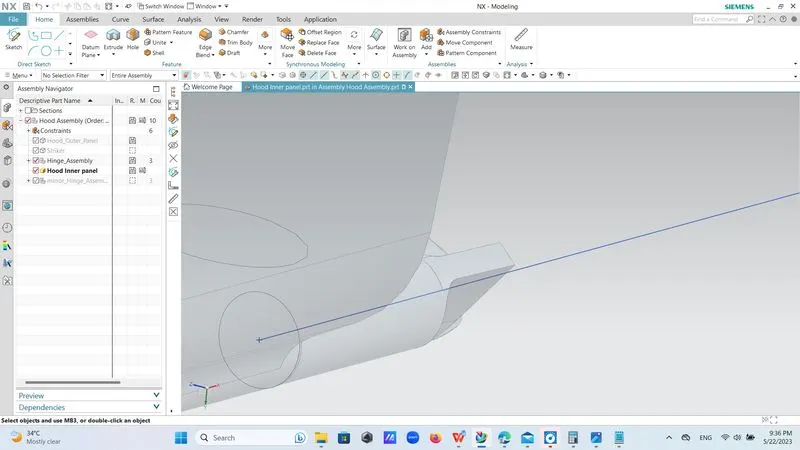
Step 23:-Now upload part striker from folder and go to the assembly section select wave geometry linker and select composite curve option and extract it then go to point option and select circle ,sphere option and take one mid point to both the side and then draw a line joining to this two points.
Go to datum plane curve as line and uptick to offset for this time and select %arc line and take 50%.so plane will come to mid line.
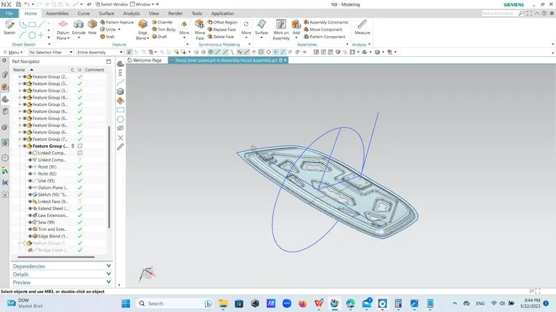
By taking this plane as reference draw a sketch of circle of radius of 700mm
And then draw a line from center of plane to circle.then draw new line from center to point on curve for this we keep mouse pointer on curve and choose one point on curve and take angle 80 deg.Then take one line from that point which is tangent to circle.
This is done for movement of striker on this curve to adjust its striker with mating part.
Constrain:
Step 24:-Go to assembly constrain choose parallel constrain and take rare surface of striker and face of surface if its not its proper position then select parallel constrain and choose datum plane and plane of striker then change direction if required.
Extraction:
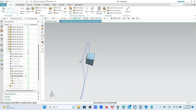
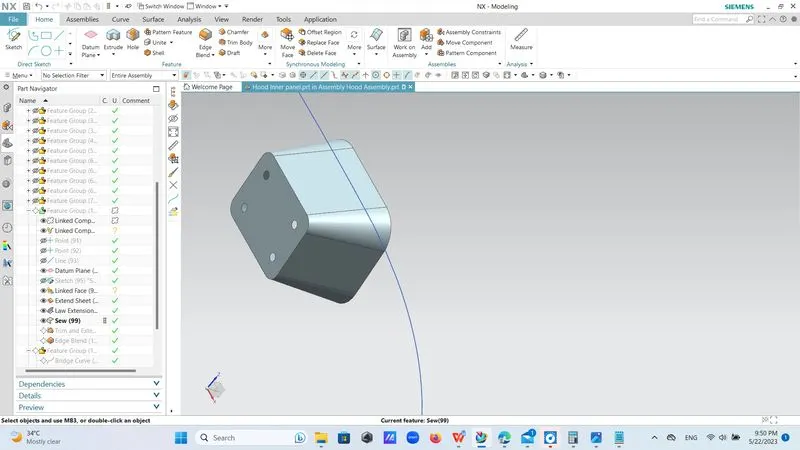
Step 25:-Select rear surface of striker rear surface by selecting assembly -wave geometry linker then by using extend sheet command extend this sheet by distance of 8mm
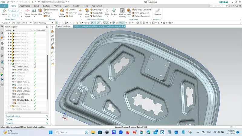
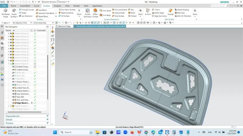
Now by using law extension command extract outer surface and chance it angle by 12 deg and length of 100mm now by using sew command join two surface then by using trim and extend command by using surface form emboss for striker.
Thicken :-
Now by using thicken command of from surface thick this surface by distance of 0.75mm
Direction of thick is must be upward for inner hood surface.
Creation of Outer Panel:-
Step 26:-By using trim surface option trim surface and them offset it by distance of [0.75+0.75+0.75+0.4=2.65] then by using offset curve in face offset it by distance of 6mm then by using trim sheet option trim its inner surface .
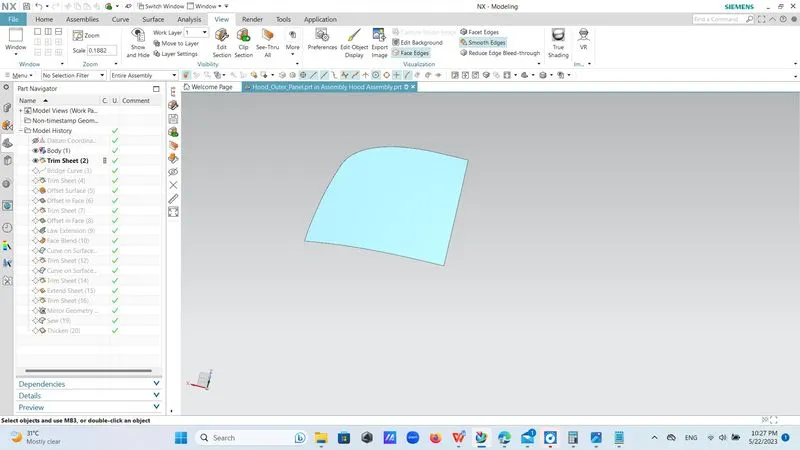
Bridge Curve :-go to curve select bridge curve option then select corners and start and end as G1 then give value for arc length of about 8mm as prviously gave in inner panel ok then go to surface then trim sheet and trim those corners.
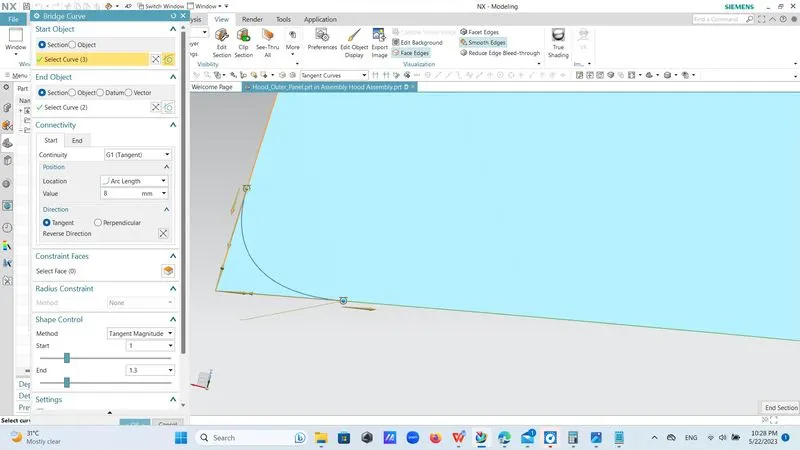
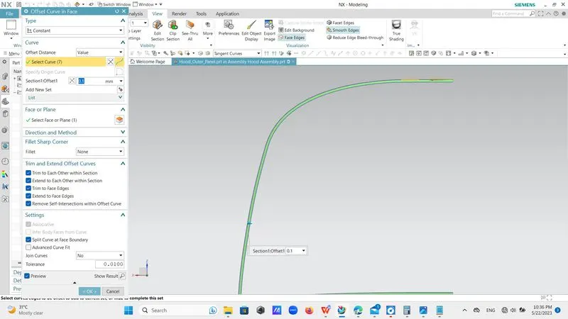
Step 28:-Again by doing offset curve in face option from curve offset it by distance of 0.1mm forward and then used bridge curve option then select start option -section and end option - section then selecting curve for both then connectivity continuity G1 start with start point for tangential slope and end with G1 for smooth ending of curve option and to keep distance of at lest of 3mm from outer boundary for better strength of curve .if there any corner and then trimmed off outer part by trim sheet option.
About pane
Face Blend:-
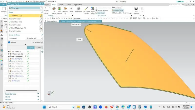
Step 27:- By taking face blend option and three face selected and choose first face top surface arrow direction downward second face downward face and arrow facing upward and third face is mid face.and ok gives roiling ball
Curve on surface:- then select curve on surface from curve option draw curve at all shrap corners and then srart point and end points are G1 for smooth tangential surface keep gap between two cuves as 3 or less than 3mm for better strength for rolling .then trim this sheet by using surface and trim sheet command.

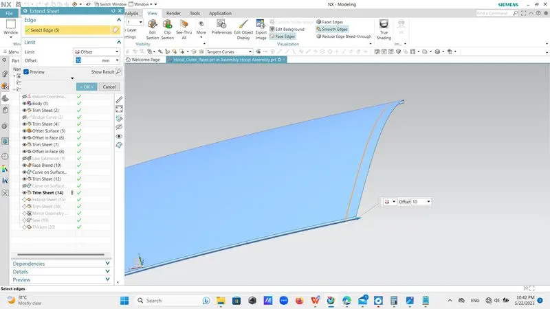
Step 29:-again by using extend sheet and trim sheet option mirror and sew it.
Thicken :
Step 30:- Thicken this surface by distance of 0.75mm..
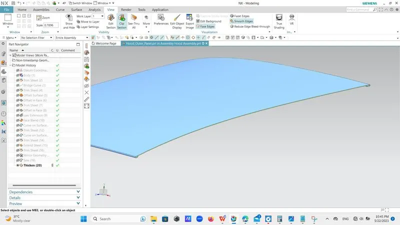
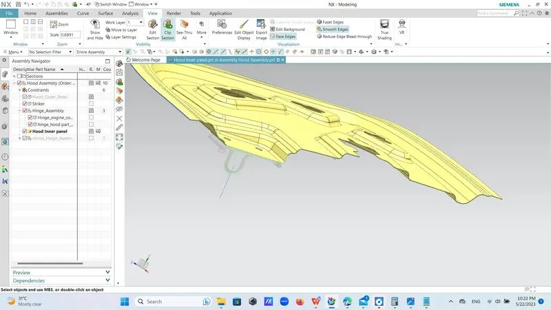
Step 31:-Go to view tool box there is clip section where Assembly is trimmed into two parts now go to edit clip and select section and then plane which one you want to take section .
Step 32:-Gap between two surfaces are I.e. inner surface and outer surface hood must be 5mm so go to Analysis and measure distance between them if it is more then 5mm then adjust to embossed height to keep this distance clear.
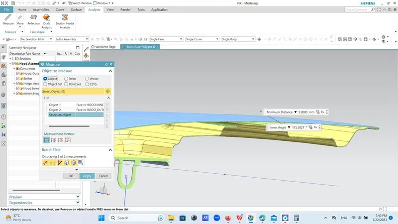
Step 33:-checked length of inner panel if it is more then by cutting inner boundaries of it for clearance of at least 2.. from side.
Draft Analysis:-
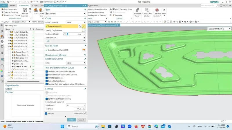
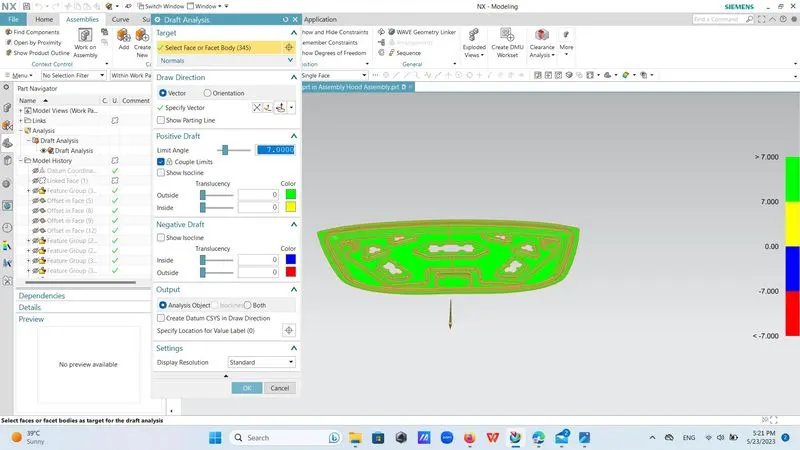
Step34:-Go to Hood Inner panel and then go to Analysis there is click on ribbon option on left most arrow and go to face shape group and tick on draft analysis and then select face or face body tangential face and entire selection and then select drew direction as vector and specify vector as tool axis change its direction if needed.give draft angle as 7 deg click on OK.
Section Modulus of Hood:-
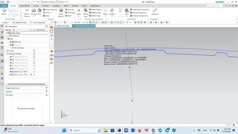
Step 35:- Go to surface and in an assembly and select wave geometry linker then go to datum plane and select mid line as curve and arc length about 50% to get this plane in middle of section and then go to curve and select intersection curve between two sets of objects select assembly and select datum plane as intersection.
Will get intersection of outer and inner panel and then go to sketch through respective plane
Now in this sketch there is no part of intersection so go to profile tab and select project curve option and select single curve and select upper and lower curve separately this curves are not attached to each other so do attached them in an sketch and then finish sketch
Go to the command finder of title box and type section inertia analysis and will get min and max moment of inertia we have to choose min moment of inertia.
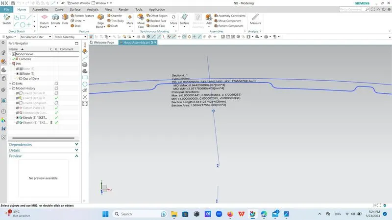
Again go to same sketch there are various options choose offset curve from it offset it by 5mm then finish sketch and select new sketch project this new offset and upper profile in this sketch join them by corner method or trimming process and finish sketch go to search and choose section inertia analysis and check moment of inertia and compare between two moment of inertia which one is max as maximum as moment of inertia its strength will also maximum.
Formula:-
Z=I/Y
Z:- section modulus
I:- Moment of Inertia
Y:-distance of neutral axis with respective two coroners
- Moment of inertia is directly proportional to strength
- as moment of inertia increase strength also increase.
- Hemming gum:-
- There is clearance between upper surface and lower surface of 0.2 mm and this gap is filed with hemming gum .
- Hemming is the process of joining both the outer and inner panel together. The hemming process roles and wraps the hood outer panel around the inner panel and holds it tightly together. The gap between the hemming flanges of hood outer panel to inner panel will be filled with sealants to make the joint as waterproof. After the hemming is done, we need to provide corner relief at the corners of the hood so that the part can be produced without defects. See the below pictures of Hemming and the reliefs provided at the corners.
-
I 2> I 1 so here moment of inertia 2 is greater than first so strenth incresed here.sr Moment of inertia Distance Modulus 0 M D Z 1 3.025427374 217.10685 0.0139351 2 3.071783695 217.10685 0.01414871