Hood design-Week 2
AIM
- To design Hood Outer Panel, Inner Panel and the necessary reinforcements by following the Master Section mentioned with the given design parameters using Catia V5.
OBJECTIVE
- This project deals with the detailing of hood introduction, hood types, hood components and proper explanation of procedure to be followed to design the hood outer panel, hood inner panel and along with the required reinforcements. In this project the master section was given for the reference along with the parameters for the hood design. Along with that, hinge and striker mountings are also designed and all the components were assembled together. Finally, the draft analysis were performed on the inner panel to check the manufacturing feasibility.
METHODLOGY
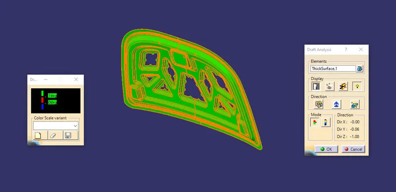
- Develop the hood inner panel with embossing with minimum draft angle of 7 degree.
- Performing feature draft analysis on the hood inner panel.
- Creating a hood outer panel with hemming.
- Positioning the reinforcements such as hinges and striker for latch
- Assembling all the components in the assembly workbench.
INTRODUCTION
- The hood or bonnet is the hinged cover over the engine of motor vehicles. Hoods can open to allow access to the engine compartment, or trunk on rear-engine and some mid-engine vehicles for maintenance and repair.
- On front-engined cars, the hood may be hinged at either the front or the rear edge, or in earlier models (e.g. the Ford Model T) it may be split into two sections, one each side, each hinged along the centre line. Another variant combines the bonnet and wheel arches into one section which allows the entire front bodywork to tilt forwards around a pivot near the front of the vehicle.
HOOD MATERIALS
- Hoods are typically made of the same material as the rest of the body work. This may include steel, aluminium, fiberglass or carbon fiber. Some aftermarket companies produce replacements for steel hoods in fiberglass or carbon fiber to reduce vehicle weight.
HOOD TYPES
- Front Hood
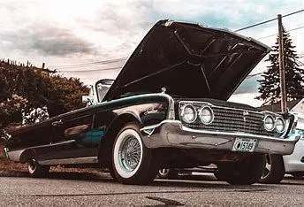
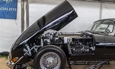
- Flip-front hood &
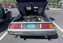
- Rear hood
HOOD FEATURES
- Windshield washer nozzle
- Scoops
- Ram air intake scoops
- Shaker scoops
- Cowl induction scoops
- Intercooler scoops
- Louver vents
- Hood pins
- Hood locks
COMPONENTS OF HOOD
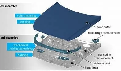
- Hood Outer Panel
- Hood Inner Panel
- Hinge
- Latch & Striker
- Support Rod
- Gas Stay
Hood Outer Panel
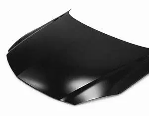
- Outer panel is the outer most part of the hood which is visible to us when the hood is in the closed position. The outside panels provide the shape of the car body whereas the inner panels reinforce the shell of the body. The various curved shapes are given to outer panels to provide the strength to panels.
Hood Inner Panel
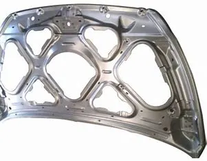
- Inner panel of the hood includes the main body of the hood. It is the main part of the hood that houses the hinge, latch, and striker reinforcements along with the embosses. The inner panels provide mounting locations for various trim panels and connecting assemblies.
Hinges
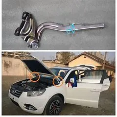
- A car hood hinge is a specialized engineering component that attaches a car’s hood (engine cover) to the rest of the vehicle. It is a critical part of the car’s design, and must be carefully engineered to allow the hood to open and close smoothly. Hood hinges are usually located near the front of the vehicle, just behind the headlights.
- The car hood hinge is a device that attaches to the top of the car and allows it to open up like a door. It can be used to provide access to the engine compartment, or simply as an aesthetic feature.
Latch & Striker
- The latch is usually located inside the car, near the driver or front passenger. The lock is usually located on the outside of the car, near the front of the hood.
- To open the hood, first locate the latch inside the car. disengage the latch by pulling on the release handle or pushing on the release button. Once the latch is disengaged, lift up on the hood to release it from the closed position.
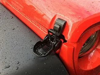
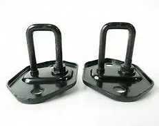
- A hood striker for a vehicle is provided to minimize injure of a car accident person due to an impact force caused by a car crash through installing a resilient member to absorb the impact force to be transferred to a hood striker.
- It bolts to the underside of the hood at the front. It engages the hood latch when closed.
Support Rod
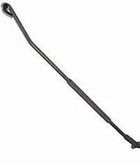
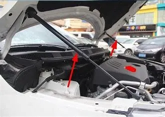
- The hood support struts hold up the hood of your vehicle. This allows you to access the engine compartment without holding the hood up by hand or with a prop rod. Failed hood struts can be both dangerous and annoying as they could allow the hood to fall on your head.
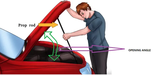
- Here the length of the rod is an important factor because that decides the opening angle of the hood. The support rod is attached to the hinges.
Gas Stay
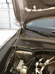
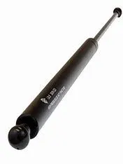
- It is also a type of hood stay but it is automated. It just requires an initial thrust and then the gas itself actuates and works desirably. Gas stay is generally used when the weight of the hood is more so to help the person lifting it as it would be difficult for him to hold it. stud balls are generally used for connecting the gas stay.
DESIGN CONSIDERATION OF HOOD
Hood Opening Angle
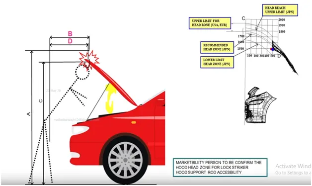
- The opening factor is very important factor in hood design. While accessing the engine compartment hood will be open at desirable angle. The opening angle is decided based on the average height of the person in that region.
Hood Regulations
EURO NCAP Assessment
- The European New Car Assessment Programme (Euro NCAP) is a European voluntary car safety performance assessment programme.
- It is an independent crash-test safety body, which rigorously assesses the safety of cars, and helps to further the advancement of car safety technology. With safety at the forefront of all car makers minds, and many firms and organisations signing up to the ‘Vision Zero’ initiative – which aims to eliminate all deaths and serious injuries from our roads – Euro NCAP’s test programme is an ever-evolving one, with its architects periodically updating crash-test regimes to ensure cars are assessed using the most stringent criteria possible.
CATEGORY 1
PEDESTRAIN SAFETY
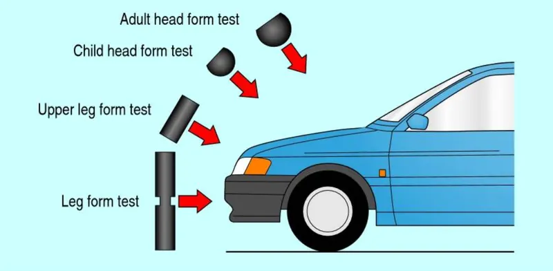
- Euro NCAP tests three accident scenarios in which the pedestrian crosses directly in front of the path of the test vehicle, one in which the pedestrian is walking in the same direction as the vehicle, one in which the pedestrian is crossing a road into which the test car is turning and one where a pedestrian is behind the reversing car.
- Regulations have come into effect that place a limit on the severity of pedestrian head injury when struck by a motor vehicle. This is leading to more advanced hood designs
HEAD IMPACT
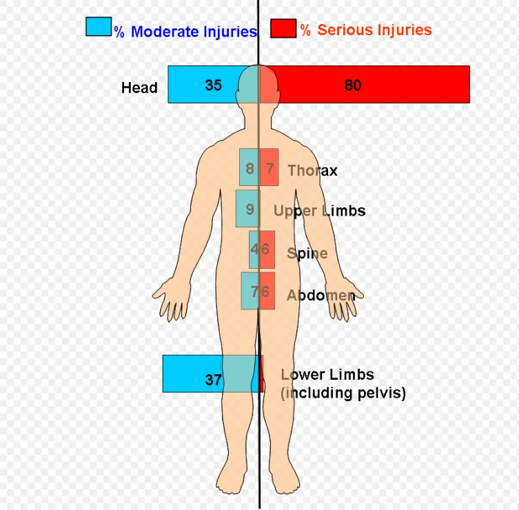
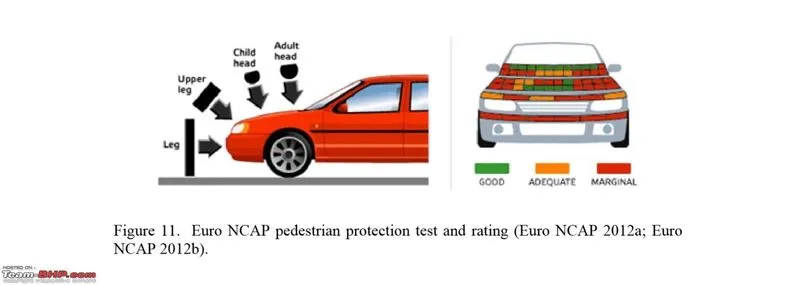
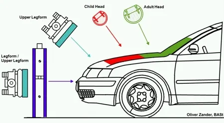
- Car-pedestrian accidents account for a considerable numbers of automobile accidents in industrialised countries. Head injury continues to be more concerned with automobiles impacts, because the head is the most seriously injured part in many collisions including in pedestrian automobile collisions. To reduce the severity of such injuries international safety committee have proposed sub-system tests in which head foam impactors are impacted upon the car hood
- Safety is the most important criteria in automobile design which concentrates on both pedestrian and occupant safety. The pedestrians are the most vulnerable road users are at high risk of traffic accidents. The major reason for fatality of the pedestrian in traffic accidents is due to the head injury resulting from the hard impact of the head against the stiffer hood of the ground. This leads to the necessity of new inner hood panel which is less stiffer an pedestrian friendly.
- In this, the Adult and Child impact zone is taken into consideration and calculated by plotting the regions from the model data. In the model in this case the outer panel is offset to generate the deformation space in the engine compartment below the styling surface and thereby determining the interference. All these tests are conducted with the help of a dummy that is been hit by a car at 40 km /hr speed.
WARP AROUND DISTANCE
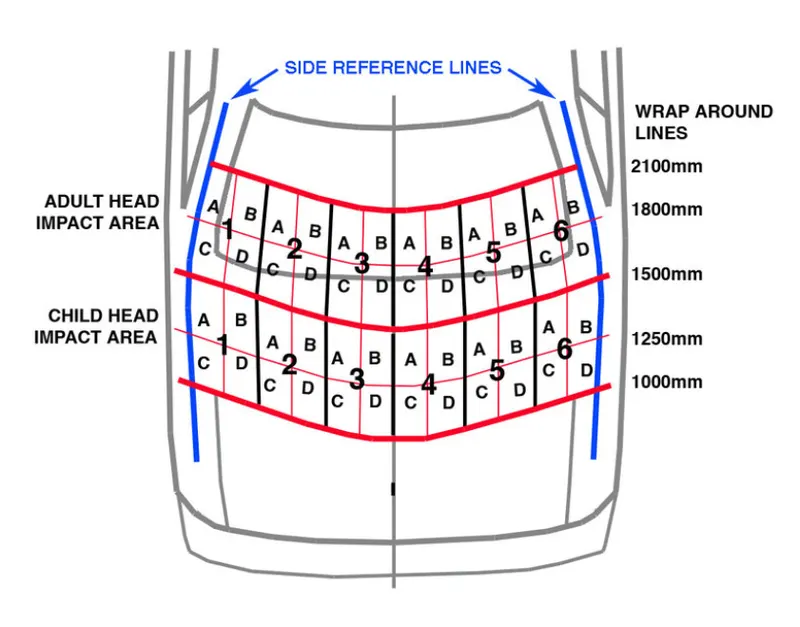
- During most pedestrian-vehicle crashes the car front impacts the pedestrian and the whole body wraps around the front shape of the car. This influences the head impact on the vehicle. Meanwhile the windscreen is a major impact point and tested in NCAP conditions. The severity of injuries is influenced by car impact speed; type of vehicle; stiffness and shape of the vehicle; nature of the front (such as the bumper height, bonnet height and length, windscreen frame); age and body height of the pedestrian; and standing position of the pedestrian relative to the vehicle front. The so called Wrap Around Distance WAD is one of the important measurements for the assessment of protection of pedestrians.
- When a car crashes on the pedestrian, the whole human body wraps around the front shape of the car, and the head impacts on the bonnet or the windscreen.
- The severity of the injury caused by the frontal crash depends on the type and shape of the vehicle, the speed of the vehicle, and the movement of the pedestrian relative to the vehicle. In addition to these parameters, the wrap around distance plays a major role in the safety measures of a pedestrian.
- During crash analysis, based on the wrap around distance, two test areas will be created namely the Child Head Impact Zone and the Adult Head Impact Zone.
Test Reports
- The head impact zone for child is around 1000 WAD to 1500 WAD.
- The head impact zone for adult is around 1500 WAD to 2100 WAD.
CATEGORY 2
PASSENGER SAFETY
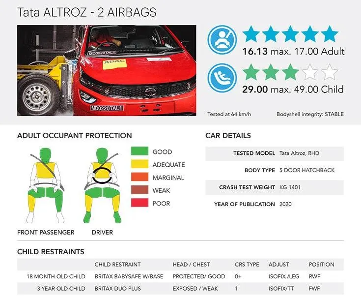
- Along with the pedestrian safety, the passenger safety is also important in NCAP. Adult Occupant Protection The Adult Occupant Protection score is determined from frontal impact, lateral impact and whiplash tests, which are done to evaluate the protection of adult driver and passengers offered by the vehicle, and from an assessment of the measures provided for prompt and safe rescue and extrication.
- The Passenger safety test taken for TATA Altroz.
MASTIC SEALANTS
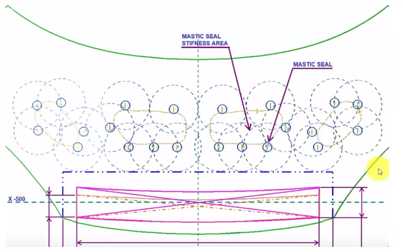
- The mastic sealant can act as a protecting layer between elements. The features of this sealant and how it works makes it different from the others. It forms a smooth exterior which makes the surface flexible while maintaining a hard plastic beneath the surface.
- Due to its flexibility, the sealant can be sued on different surfaces without preparing the surfaces first.
- To improve NVH (noise, vibrations, harshness), mastic sealants were provided on the inner panel to attach with outer panel. Here mastic points on the inner panel plays a major role to avoid Noise and Vibration into the cabin. NVH is measured by the instruments, namely microphones, accelerometer and force gauges, or load cells. Component and sub-assembly NVH tests are most commonly performed using a vibration shanker while entire vehicles usually on the test track or road simulator test-beds.
EMBOSS
- Emboss are provided in the inner panel of the hood assembly. This helps in weight reduction of the hood and also to dissipate the force during collision
MANUFACTURING PROCESSES OF HOOD
POINTS TO BE CONSIDERED FOR FEASIBLE MANUFACTURING
- First, the draft analysis of the sheet metal should be minimum 7 degrees.
- Then there should not be any sharp edges in the BIW component while manufacturing.
SHEETMETAL OPERATIONS
- Embossing
- Hemming
- Deep Drawing
EMBOSSING OPERATION
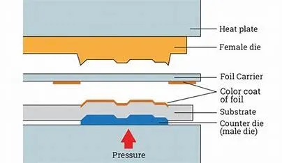
- Embossing is a stamping process for producing raised or sunken designs or relief in sheetmetal. This process can be made by means of matched male and female roller dies, or by- passing sheet or a strip of metal between rolls of the desired pattern, theoretically with no change in metal thickness, or by passing sheet or a strip of metal between rolls of the desired pattern.
- Metal sheet is drawn through the male and female roller dies producing a pattern or design on the metal sheet. Depending on the roller dies used, different patterns can be produced on the metal sheet.
- Emboss should be in 7 degree to 25 degree inclined in angle and it should not be in 90 degree angle, why because when we do stamping in manufacturing the stamping tool fits the sheet metal hence it will not come out of that sheet metal.
HEMMING OPERATION
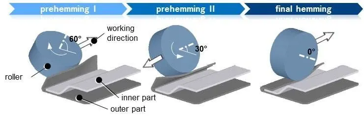
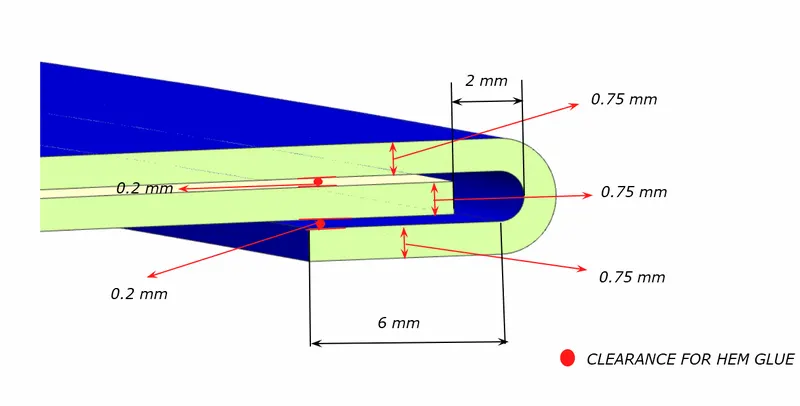
- Hemming is a forming operation in which the edges of the sheet are folded or folded over another part in order to achieve a tight fit. Hemming is a technology used in the automotive industry to join inner and outer closure panels together (hoods, doors, tailgates, etc.). It is the process of bending/folding the flange of the outer panel over the inner one. The accuracy of the operation significantly affects the appearance of the car’s outer surfaces and is therefore a critical factor in the final quality of a finished vehicle.
- In hood design, hemming is used in assembly as a secondary operation after deep drawing, trimming and flanging operations to join two sheet metal parts (outer and inner) together.
- In roller hemming process, a robot guides a small roller across the flange to fold a sheet onto itself or onto another sheet. The process is oriented to low volume automotive applications, providing a distinct advantage in manufacturing closures and subassemblies with developed flanges.
DEEP DRAWING OPERATIOIN
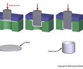
- It is a sheet metal forming process in which a sheet metal blank is radially drawn into a forming die by the mechanical action of a punch. It is thus a shape transformation process with material retention. The process is considered "deep" drawing when the depth of the drawn part exceeds its diameter. This is achieved by redrawing the part through a series of dies. The flange region (sheet metal in the die shoulder area) experiences a radial drawing stress and a tangential compressive stress due to the material retention property. These compressive stresses hoop stresses result in flange wrinkles (wrinkles of the first order). Wrinkles can be prevented by using a blank holder, the function of which is to facilitate controlled material flow into the die radius.
PROCEDURE
Data To Be Considered For Hood Creation
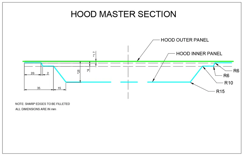
- MASTER SECTION
- HEMMING DETAILS
- RELIEF REAR SECTION
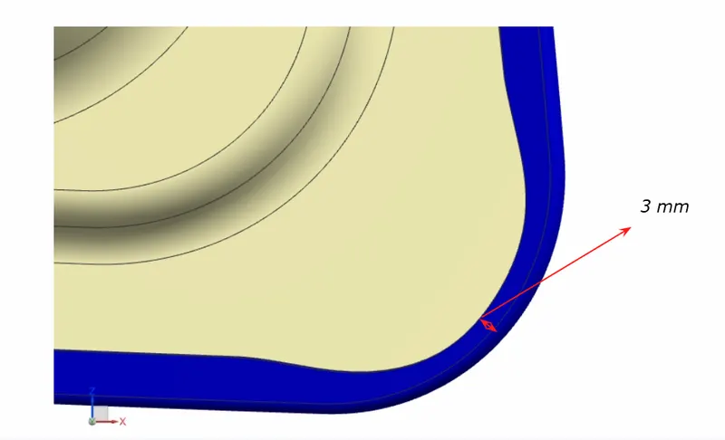
- FRONT RELIEF
Data To Be Used While Designing
- Outer Panel Thickness = 0.75 Mm
- Inner Panel Thickness = 0.75 Mm
- Reinforcement Thickness = 1.5 Mm
HOOD INNER PANEL CREATION
CREATING FLANGE
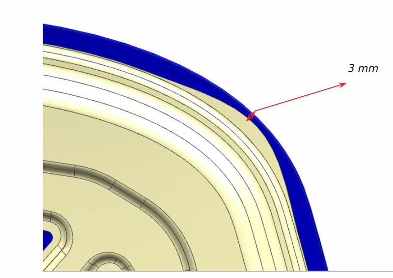
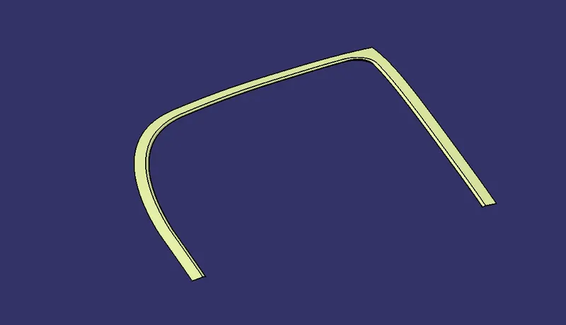
- First, the hood inner reference surface is used. The reference surface is split using the centre plane and then it is offseted to ta distance of 1.7 mm to create ther first flange.
- Then create a boundary on the offseted surface and then use paralle curve to a distance of 20 mm and use split that curve on that surface.
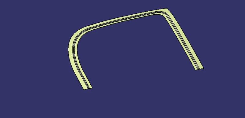
- Now, offset the reference surface with the height of 4 mm. On that surface create boundary and use parallel curve to the distance of 22 mm and 35 mm seperately.
- Now, use split option to cut the surface with those parallel curves. After doing that use multi surface section on the first flange and the second flange.
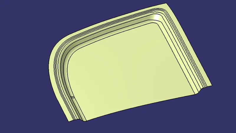
- Then, again offset the reference surface with the height of 25 mm and use boundary on it. create a parallel curve of distance of 35 mm and 50 mm seperately. then use split on the surface with those parallel curves individually.
- Use multi surface section with the second flange and the third final flange.
- Finally use shape fillet feature to give fillet to the multi sectioned surfaces and to join all. The fillet radius should be 5 to 7 mm.

CREATING EMBOSSES
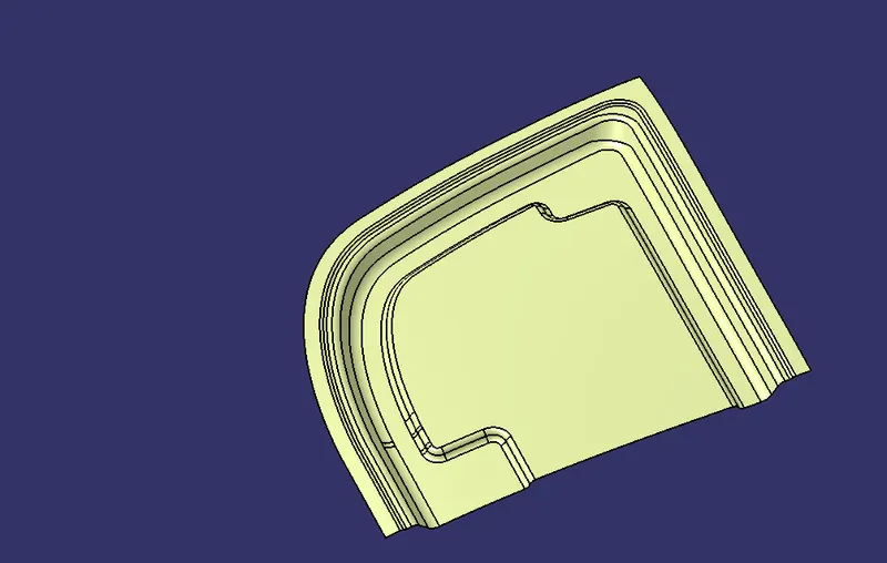
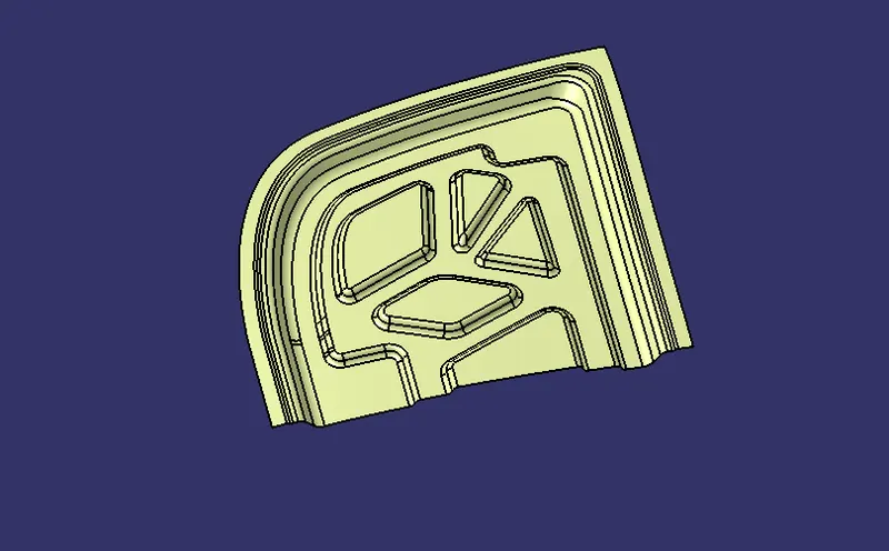
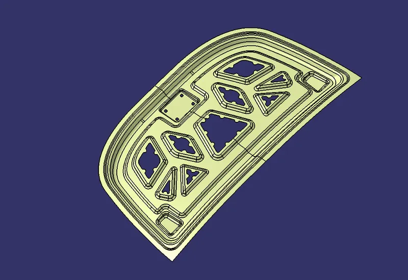
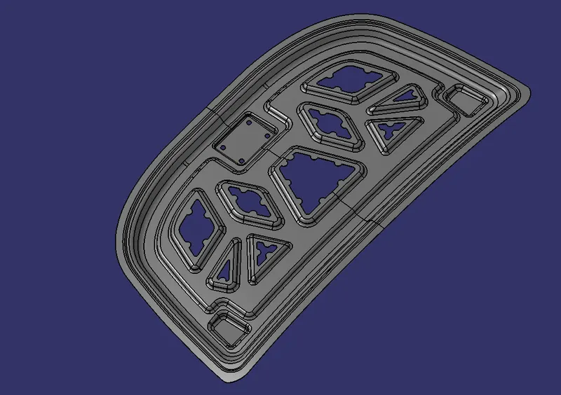
- After creating flanges, embosses are created on the flat surface of the inner panel. For creating the embosses we need to create the different shapes for the emboss as per our requirement.
- The outer emboss is created by giving clearence to the latch and flinge and to our required shape. Then contrain all the sketch and use sweep with draft direction.The draft angle should be around 15 degrees.
- Offset the reference surface to the height of 16.5 mm. And split the sweeped surface with to that offseted surface, then give shape fillet. The fillet radius should be around 5 to 7 mm.
- For creating internal embosses, create different sketches on the first emboss and constrain them and project those embosses sketches to the surface and sweep them individually.
- Now, offset the reference surface to the height of 6.5 mm and then split those sweeped emboss surface with offsetted surface.
CREATING CUTOUTS
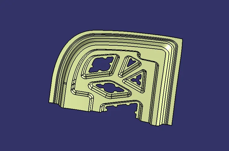
- For cutouts, we need to create a sketch within emboss of distance of 7 mm and the circle diameter should be 15 mm. After creating the sketch, split those sketches to the each embosses.
HINGE MOUNT CREATION
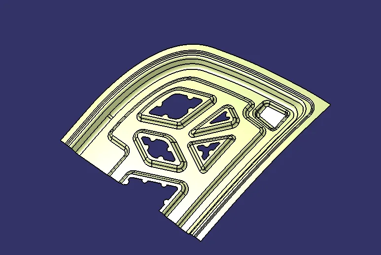
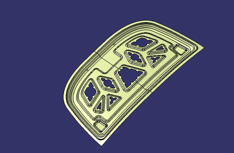
- First create a plane with 10 degree inclined to the side view of the hood and draw a sketch so the bottom surface of the hinge should seat on the mount we are about to create. Then sweep that sketch with draft direction and create a plain line sketch and extrude and use shape filllet edge feature to the both surface.

LATCH MOUNT CREATION
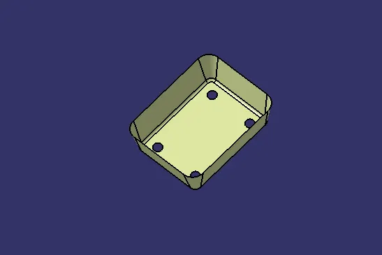
- Extract the rear surface from the given reference model and extrapolate the surface.
- Then extract the boundaries and then sweep with draft direction and use shape fillet option.
THICKENED SURFACE
HOOD OUTER PANEL CREATION
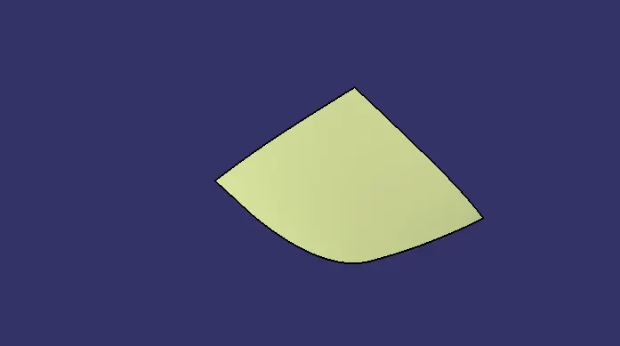
- Extract the reference surface and split it.
- Offset it to the height of 2.65 mm. Then create boundary and curve smooth and then parallel curve on the curve smooth with the distance of 6 mm.
- Split that curve with the offseted surface.
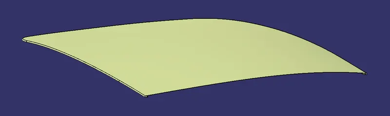
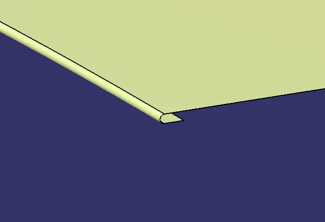
- Create a boundary and sweep that to angle of 12 to 20 degree with our requirement. and split it
- Now use Tritangent fillet on shape fillet feature for creating the hemming surface on the edges.
THICKENED SURFACE
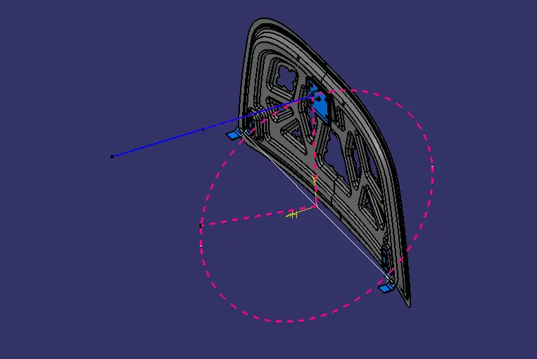
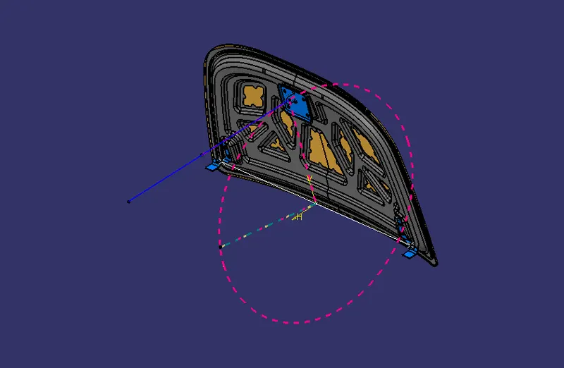
TRAJECTORY CIRCLE
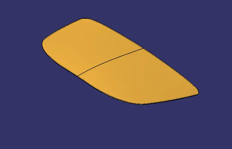
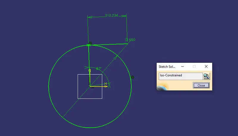
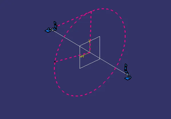
- This circle is used to locate the striker on the inner panel hood with respect to the aligning angle of about 82 to 85 degrees.
DRAFT ANALYSIS OF HOOD INNER PANEL
ASSEMBLY
- In assembly workbench, fix the hood inner panel and then insert the hinges and constrain it and use mirror feature to mirror it. then insert latch and constrain it with the trajectory circle which we have made.
MULTIPLE VIEWS
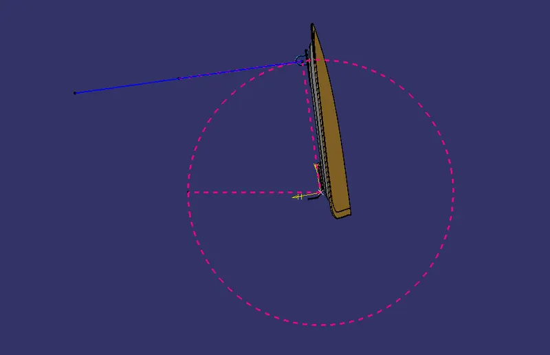
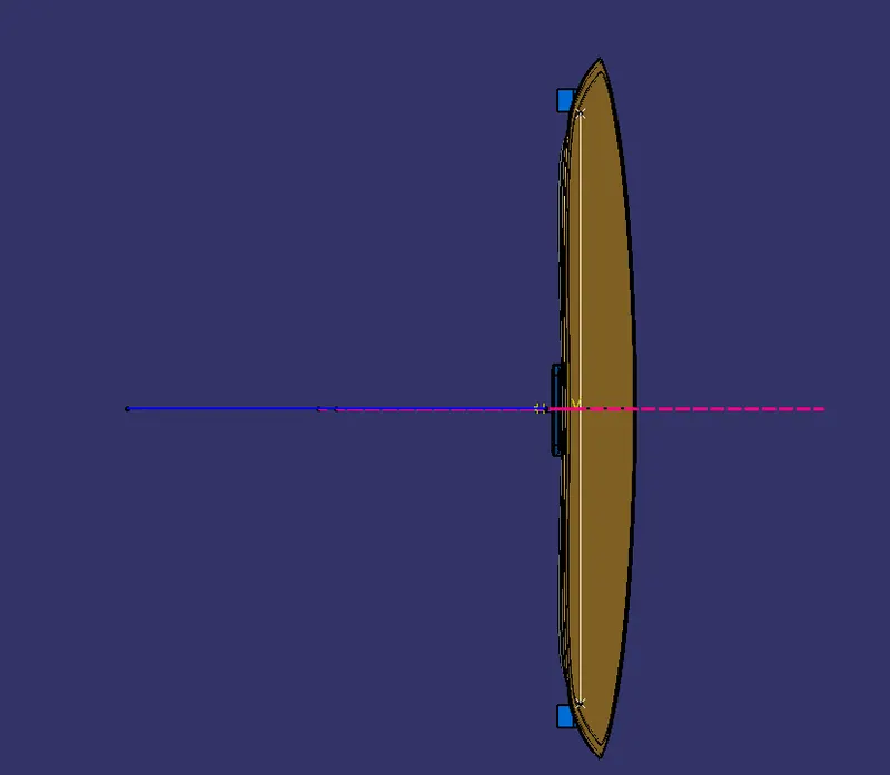
SIDE VIEW
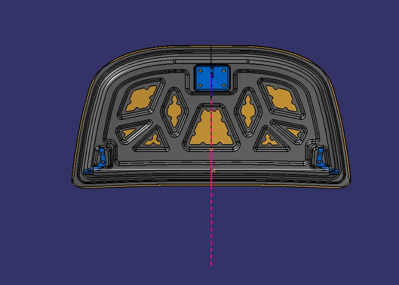
FRONT VIEW
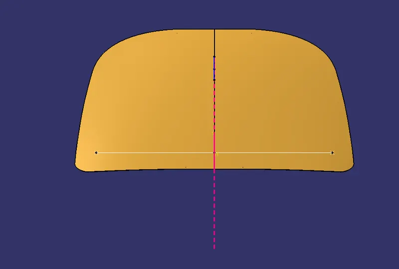
TOP VIEW
BOTTOM VIEW
CONCLUSION
Thus the Hood Outer Panel, Inner Panel and the necessary reinforcements were designed and assembled with the data given in the master section.